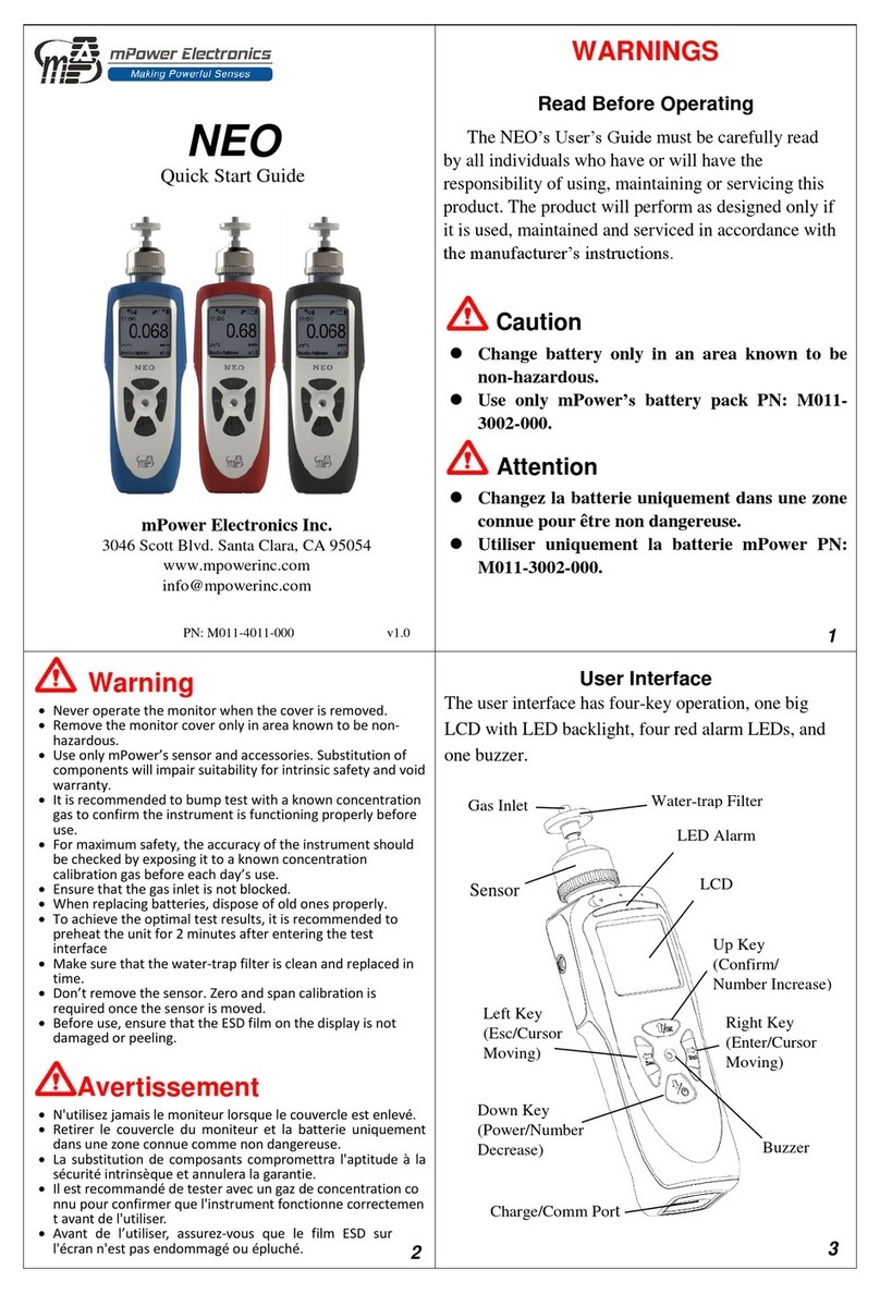
mPower Electronics NEO BENZ User manual

NEO BENZ
Photo-ionization Detector
MP186
User’s Guide
Version 1.01
November 2019

2
Contents
Read Before Operating......................................................................................................................3
General Information..........................................................................................................................4
User Interface...................................................................................................................................5
Display .............................................................................................................................................6
Charging a Lithium-Ion Battery.......................................................................................................7
Low Voltage Warning..................................................................................................................7
Clock Battery................................................................................................................................7
Data Protection While Power Is Off ............................................................................................7
Instrument Basic Functions...............................................................................................................8
Turning The Instrument On..............................................................................................................8
Turning the Instrument Off ..............................................................................................................8
Integrated Sampling Pump...............................................................................................................8
Pump Status..................................................................................................................................9
External Water-trap Filter ................................................................................................................9
Alarm Signals...................................................................................................................................9
Alarm Signal Summary................................................................................................................9
Preset Alarm Limits & Calibration ............................................................................................10
Testing The Alarms....................................................................................................................10
Backlight ........................................................................................................................................10
Datalogging....................................................................................................................................10
Man Down......................................................................................................................................10
Wireless..........................................................................................................................................10
Operating Mode Overview..............................................................................................................11
VOC Mode Main Menu .................................................................................................................11
Benzene Tube Mode Main Menu...................................................................................................12
Benzene Tube Measurements.........................................................................................................12
STEL Measurement........................................................................................................................13
Benzene Tube Replacement...........................................................................................................14
Configuration Mode.........................................................................................................................15
Navigating Config Mode................................................................................................................15
Selection From a List .................................................................................................................15
Entering Numerical Values........................................................................................................15
Entering and Exiting Config Mode................................................................................................15
Config Mode Menus.......................................................................................................................16
Calibration..................................................................................................................................18
Measurement..............................................................................................................................20
Alarm Settings............................................................................................................................21
Datalog .......................................................................................................................................22
Monitor (Mnt) Setup ..................................................................................................................23
Computer Interface Using mPower Suite......................................................................................26
Connecting and Configuring..........................................................................................................26
Custom Gas (User Gas) in VOC Mode..........................................................................................28
Datalog Retrieval............................................................................................................................29
Real-time Data................................................................................................................................30
Maintenance......................................................................................................................................31
Cleaning or Changing PID Sensor/Lamp.......................................................................................31
Lamp Cleaning and Changing....................................................................................................31
Sensor Cleaning..........................................................................................................................32
Sampling Pump..............................................................................................................................32
Troubleshooting .............................................................................................................................33
Contact Information ........................................................................................................................34

3
Read Before Operating
This manual must be carefully read by all individuals who have or will have the responsibility of
using, maintaining, or servicing this product. The product will perform as designed only if it is used,
maintained, and serviced in accordance with the manufacturer’s instructions. The user should
understand how to set the correct parameters and interpret the obtained results.
CAUTION!
To reduce the risk of electric shock, turn the power off before removing the instrument cover.
Disconnect the battery before removing sensor module for service. Never operate the instrument
when the cover is removed. Remove instrument cover and sensor module only in an area known to
be non-hazardous.
Special Notes
When the instrument is taken out of the transport case and turned on for the first time, there
may be some residual organic or inorganic vapor trapped inside the detector chamber. The
initial PID sensor reading may indicate a few ppm. Enter an area known to be free of any
organic vapor and turn on the instrument. After running for several minutes, the residual
vapor in the detector chamber will be cleared and the reading should return to zero.
The battery of the instrument discharges slowly even if it is turned off. If the instrument
has not been charged for one week, the battery voltage may be low. Therefore, it is a good
practice to always charge the instrument before using it. It is also recommended to fully
charge the instrument for at least 10 hours before the first use. Refer to this User Guide’s
section on battery charging for more information on battery charging and replacement.
Do not remove the filter when the instrument is on, otherwise, dust entry will reduce the
accuracy of measurement, shorten the life of the sensor, and possibly damage the sensor.
Benzene filtering tubes can form chromic acid when humid air is drawn through them for
extended periods. Tubes should be used for no more than a 15-minute STEL measurement
because the acid formed can severely damage the instrument if drawn into it by the
sampling pump. The quantities in each box of tubes are under the de minimus amounts for
shipment of hazardous materials; however spent tubes should be disposed of according to
local regulations.

4
WARNINGS
STATIC HAZARD: Clean only with a damp cloth.
For safety reasons, this equipment must be operated and serviced by qualified personnel only. Read
and understand the instruction manual completely before operating or servicing.
•Use only mPower battery pack M011-3002-000. Substitution of components may impair
intrinsic safety. Recharge batteries only in non-hazardous locations.
•Do not mix old and new batteries or batteries from different manufacturers.
•For maximum safety, the accuracy of the instrument should be checked by exposing it to a
known concentration calibration gas before each day’s use.
•Do not use USB/PC communication in a hazardous location.
General Information
The NEO BENZ uses a combination of a selective 9.8 eV lamp and benzene filtering tubes to
measure benzene selectively in mixtures of hydrocarbons as may be present in fuels or hazardous
waste sites. It has two main detection modes: A continuous mode for VOCs (Volatile Organic
Compounds) with a range from about 5 ppb up to 10,000 ppm, and a single-sample mode using a
filtering tube for benzene specific measurements in the range 0.05 to 200 ppm. The continuous
mode can be used to screen for benzene without a filtering tube, and if a response over the alarm
limit is detected, a tube can be inserted to measure what fraction of the alarm response was actually
due to benzene. The 45-second benzene-specific measurement time at room temperature is the
fastest on the market.
The NEO Series is one of the most advanced handheld VOC monitors available for ppb (parts per
billion) detection, offering other models from the most sensitive 1 ppb to a high range up to 15,000
ppm for different applications and user selections. Novel designs of the photo-ionization detector
(PID) and ultraviolet (UV) lamp provide outstanding sensitivity, stability and reproducibility.
Options include real time data monitoring with a built-in wireless modem using mPower Suite
application software.
Key Features
• Size: 13.7 x 2.9 x 2.2 in (350 x 74 x 55 mm) with boot and tube holder
• Weight: 28 oz (788 g)
• 50 ppb to 200 range for benzene and 5 ppb to 10000 ppm for VOC
• Fast 45-second benzene-specific response (at room temperature)
• 3-second response time for 90% change (using isobutylene in VOC mode)
• Large and intuitive display
• Integrated correction factors list of several hundred compounds
• Built-in pump for up to 30 meters sampling distance
• Man-down alarm with real-time remote wireless notification
• ISM wireless connection option
• Easy service and maintenance
• Micro-USB charge port

5
User Interface
The instrument’s user interface consists of the LCD display, Alarm LEDs, an alarm transducer, and
four keys. The keys are:
Left Key:
Right Key:
Up Key:
Down/Mode
Key:
NEO BENZ user interface
Alarm LEDs
Left Key
Move Cursor
Down/Mode
Key (On/Off)
Right Key
Move Cursor
Buzzer
Up Key
LCD
Display
Inlet Filter
Sensor Cap
Gas
Outlet
Filter Tube
Holder
USB Charge &
Comm Port

6
Display
The LCD display provides visual feedback that includes the reading, tube mode indicator, pump
status, Man-Down, time, battery condition, and other parameters.
The display shows the following information:
LCD display
Item
Description
Gas Name and CF
Shows the measurement gas and its correction factor
Reading
Concentration of gas measured by the instrument
Tube Mode
Indicates unit is in tube sampling mode
Calibration Due
Cylinder icon appears when calibration is due
Pump Status
Indicates whether the pump is working or blocked
Man-Down Status
Icon appears when Man-Down alarm is enabled
Lamp Status
Lamp icon is shining when on and crossed out when off
Bluetooth Enabled
Local Wireless Communication is enabled
Datalog On
Verifies that datalogging is on
Battery Status
Indicates battery capacity in 3 bars
Time
Indicates current time or STEL sampling time remaining
Temperature
Indicates current temperature inside the instrument
Time
Pump Status
Temperature
Battery Status
Datalog On
Concentration
Reading &
Unit
Gas Correction
Factor
Calibration/Bump Status
Man-Down
Enabled
Lamp Status
Alarm
Notice
Calibration Due
Tube Mode Indicator
Gas Name
Bluetooth On

7
Charging a Lithium-Ion Battery
Always fully charge the battery before using the instrument. The screen will display a battery icon
from empty (no bars) to fully charged (3 bars).
Follow this procedure to charge the instrument:
1. Plug the Micro-USB into the charging port at the bottom of the instrument.
2. Plug the USB connector* into either a) a personal computer, or b) into the AC/DC
adapter and plug the AC/DC adapter into the wall outlet.
The instrument begins charging automatically. The charging LED turns red to indicate
charging. During charging, the 3 bars in the battery icon on the instrument’s display are
animated. When the battery is fully charged, the LED turns green, the icon is no longer
animated and shows a full battery, and the message ‘Fully Charged’ is displayed.
*NOTE: Any locally-obtained USB A to Micro B USB cable will work for charging, but will not
work for communication with mPower Suite configuration and data transfer software. The mPower
USB cable P/N M-011-3003-000 is required for a PC to recognize the instrument and communicate
with mPower Suite.
WARNING!
To reduce the risk of ignition of hazardous atmospheres, recharge and replace batteries only in areas
known to be non-hazardous. Use only mPower’s rechargeable lithium battery part number:
M011-3002-000.
Low Voltage Warning
When the battery’s charge falls below a preset voltage, the instrument warns you by
beeping once and flashing once every minute, and the “empty battery” icon blinks on and
off once per second. Turn off the instrument within 10 minutes and either recharge the
battery, or replace the battery with a fully charged one.
Clock Battery
An internal clock battery is mounted on one of the instrument’s printed circuit boards. This long-life
battery keeps settings in memory from being lost whenever the Li-ion battery or alkaline batteries
are removed. This backup battery should last approximately five years, and must be replaced by an
authorized mPower service technician. It is not user-replaceable.
Data Protection While Power Is Off
When the instrument is turned off, all the current real-time data including last measured values are
erased. However, the logged data are preserved in non-volatile memory, so that even if the battery is
disconnected, the logged data will not be lost.

8
Instrument Basic Functions
The NEO gives real-time measurements or single-point benzene measurements and activates alarm
signals whenever the reading exceeds preset limits. Prior to factory shipment, the instrument is
preset with default alarm limits and the sensor is pre-calibrated with standard calibration gas.
However, the instrument should be tested and the calibration verified before the first use. After the
instrument is fully charged and calibrated, it is ready for immediate operation.
Turning The Instrument On
Press and hold the Mode (Down) key until the display, beep buzzer & LEDs turn on.
If the mPower logo does not appear first, there is likely a problem and a distributor or mPower
Technical Support should be contacted. The instrument then performs self-tests after the screen
displays the firmware version and serial number.
Self-tests include:
After self-tests, the instrument will show sensor information and instrument configuration
information in sequence. Once the startup procedure is complete, and a numerical reading screen
with icons is displayed, the instrument is fully functional and ready for use.
Turning the Instrument Off
Press and hold the Down key for 3 seconds, and continue to hold for a 5-second countdown
until “Unit off...”is displayed.
Integrated Sampling Pump
The instrument includes an integrated, diaphragm-type sampling pump that can operate at low or
high speed, ranging from about 300 to 430 cc/min, respectively, with no filters, 260 to 390 cc/min
with a standard 0.45 µm filter in place, and about 240 to 350 cc/min with both a benzene tube and
0.45 µm filter. Flow will decrease if the 0.45 µm filter accumulates particulate matter, or if a filter is
not used and particles get caught in the pump diaphragm. Connecting Teflon tubing with 1/8" inside
diameter to the gas inlet port, this pump can pull air samples from 200' (61 m) away horizontally, or
Clock…..
Wireless….. OK

9
90' (27.5 m) vertically, at about 3' (0.9 m) per second flow rate. Note that at 200’the PID response
will be delayed by about 1 minute, the time required for the gas sample to reach the instrument.
IMPORTANT!
During operation, make sure the probe inlet and the gas outlet are free of obstructions. Obstructions
can cause premature wear on the pump, false readings, or pump stalling.
Pump Status
During normal operation, the pump icon alternately shows inflow and outflow. If
there is a pump failure or obstruction, the alarm sounds and the pump stall icon
blinks on and off. If this occurs, clear the obstruction and press the Right key to
restart the pump.
External Water-trap Filter
The external filter is made of a PTFE (Teflon) or PVDF membrane with 0.45 micron pore size to
prevent dust or other particles from being sucked into the sensor manifold, which could damage the
instrument. It prolongs the operating life of the sensor and pump. To install the external filter,
simply screw it in to the instrument’s inlet probe using the Luer connection.
Alarm Signals
During each measurement period, the gas concentration is compared with the programmed alarm
limits (gas concentration alarm limit settings). If the concentration exceeds any of the preset limits,
the loud buzzer and red flashing LED are activated immediately to warn of the alarm condition.
In addition, the instrument alarms if one of the following conditions occurs: battery voltage falls
below a preset voltage level, failure of the UV lamp, or pump stall.
Alarm Signal Summary
Message
Condition
Alarm Signal
HIGH
Gas exceeds ‘High Alarm’limit
3 beeps/flashes per second
OVR
Gas exceeds measurement range
3 beeps/flashes per second
MAX
Gas exceeds electronics’ max range
3 beeps/flashes per second
LOW
Gas exceeds ‘Low Alarm’limit
2 beeps/flashes per second
TWA
Gas exceeds ‘TWA Alarm’limit
1 Beep/flash per second
STEL
Gas exceeds ‘STEL Alarm’limit
1 Beep/flash per second
Remove Tube
STEL measurement completed
1 Beep/flash per second
Pump icon flashes
Pump failure
3 beeps/flashes per second
Lamp
PID lamp failure
3 beeps/flashes per second
plus ‘Lamp’message
Battery icon
flashes
Low battery
1 flash, 1 beep per minute plus
battery icon flashes
CAL
Calibration failed, or is overdue
1 beep/flash per second
NEG
Gas reading measures less than
number stored in calibration
1 beep/flash per second

10
Preset Alarm Limits & Calibration
The instrument is factory calibrated with standard calibration gas, and is programmed with the
following default alarm limits:
Cal Gas
Cal Span
unit
Low
High
TWA
STEL
Benzene
5
ppm
0.5
2.5
0.5
2.5
Isobutylene
10
ppm
50
100
10
25
Alarm limits and calibration parameters can be adjusted in Configuration Mode as desired for
particular testing purposes and applications.
Testing The Alarms
The alarm can be tested whenever the main (Reading) display is shown. Press the Right key, and the
audible and visible alarms are tested.
Backlight
The LCD display is equipped with an LED backlight to assist in reading the display under poor
lighting conditions. Background lights can be turned on automatically under poor light condition
and be set in a variety of ways. We can choose from the settings menu under Config Mode or
through mPower Suite.
Datalogging
During datalogging, the instrument displays a disk icon to indicate that datalogging is enabled. The
default status is to have datalogging on, at 60-second intervals, which allows up to one year of data
storage.
The instrument stores the measured gas concentration at the end of every sample interval (when
datalogging is enabled). In addition, the following information is stored: user ID, site ID, serial
number, last calibration date, and alarm limits. All data are retained (even after the unit is turned
off) in non-volatile memory so that it can be down-loaded at a later time to a PC. Stored data are
organized into ‘events’, with a new event created each time the instrument is turned on, or a
configuration parameter is changed, or datalogging is interrupted.
After an event is recorded, the unit records a shorter form of the data. When transferred to a PC
running mPower Suite, these data are arranged with a sample number, time, date, gas concentration.
Man Down
Settings are available for On/Off depending on the user’s requirement.
The Man Down Alarm is a critical and potentially lifesaving safety feature of the NEO. Its function
is based on the premise that if the instrument is motionless when it is not supposed to be, its user
may be in distress. If that is the case, the NEO not only goes into alarm locally on the instrument,
but also remotely, over a wireless network, to notify people in the vicinity, as well as remote safety
officers at a command center, that a person is down, so that help can be dispatched quickly.
Note: Remote notification requires wireless connection to a network.
Wireless
When NEO is equipped with wireless capability, it is set up through the wireless sub-menu.

11
Operating Mode Overview
The instrument works in either VOC Mode for continuous VOC readings or Tube Mode for
single-point benzene-specific measurements. The VOC Mode can be configured to read any desired
gas using any correction factor (CF) or lamp, whereas the Tube Mode can only be used for benzene
measurements with a 9.8 eV lamp. When the unit is turned on, it enters VOC Main Mode. To
switch between VOC Mode and Tube Mode, press and hold the Left and Right keys
simultaneously for a few seconds. In each of these main modes, basic users can only see and use a
limited set of functions. Advanced users can access the Configuration Mode, which is password
protected, to adjust various parameters. The Configuration Modes are slightly different depending
on whether one is entering from VOC Mode or Tube Mode. Some parameters are not accessible on
the instrument display and the mPower Suite software must be used to change the settings.
VOC Mode Main Menu
TheVOC MainModescreenshows real-timereadingsand auxiliary information.Pressthe Up key
or Down key to cycle through the sub-menu screens.
Flow chart for VOC Main Mode
VOC Main Mode
Continuous VOC Readings
Tube (Benzene) Main Mode
Continuous Benzene Screening
Other Tube (Benzene) Sub-Menus
Single-Point Benzene Tube Measurement
Configuration Mode (Tube)
Hold
Up &
Down
Hold Left & Right
Configuration Mode (VOC)
Hold
Up &
Down
VOC Mode Sub-Menus
Down
Down (Insert Tube)
Down
Reset TWA, STEL
and Peak?
Right
Switching to
Tube Mode
Hold
Left
&
Right
Down
Up
Down
Down
Down
Down
Down
Up
Up
Up
Wireless Type:
mPower BLE
Up
Right
Up
Left
Left

12
Benzene Tube Mode Main Menu
TheBenzeneModemainscreenshowsreal-time readingsand auxiliaryinformation.Press the Up or Down
key to cycle through the sub-menu screens.
Flow chart for Tube (Benzene) Main Mode
Benzene Tube Measurements
1.Ensure that the monitor is zeroed and calibrated a) in Benzene Mode, b) with 5 ppm benzene
AND c) using a benzene tube.
2.Use Continuous Benzene Screening Mode (Tube Main Mode) to continuously monitor for
benzene without a filtering tube.
3.If a reading above the alarm limit is found, take a single-point benzene measurement using a tube,
as follows:
a. From Benzene Screening Mode (Tube Main Mode), press Down.
b. When asked to start sampling, press the Right key.
c. Enter the temperature using the Up & Down keys to increase or decrease and the Right & Left
keys to move the cursor. Move to √and press Up. The temperature entered is that of the air to
be sampled, not the internal instrument temperature. If the tube is warmed to shorten sampling
time, enter the average of the air and tube temperatures.
Switching to
VOC Mode
Hold
Left
&
Right
Down
Right
Up
Left
Down
Up
Down
Up
Reset TWA, STEL
and Peak?
Right
Down
Up
Down
Down
Down
Down
Up
Up
Up
Last Meas.
Benzene
371 ppb
STEL
926 ppb
Up
Left
Right
Current Temp.
+2 5 °C
×
Tube: Benzene
Start Sampling?
Please Insert Tube
Press Right Key
To Start
×/Up
Up
Wireless Type:
mPower BLE
Right
Current Temp.
+2 5 °C
×
Tube: Benzene
Start Sampling?
Please Insert Tube
Press Right Key
To Start
×/Up
Up
Down
Up
Wait . . .
45
Up

13
d. When prompted to insert a tube, open both ends of a benzene filtering tube using the tube tip
breaker, taking caution to protect eyes and hands from sharp glass pieces.
e. Unscrew the top section of the tube holder, insert the tube with the arrow pointing towards the
instrument, and screw the top section back on.
f. Briefly hold a finger on the probe tip and listen for a strain on the pump, to ensure flow is
blocked and thus check for a good seal on the tube.
g. Direct the probe to the sampling point and press the Up key to start a count-down timer. The
sampling time is 45 s at room temperature, but ranges from 30 s to 360 s depending on temp.
h. Press Left at any time to abort the measurement.
Benzene Tube Measurement Time vs Temperature
Temp. °C
-10 to -6
-5 to -1
0 to +4
+5 to +9
+10 to +19
+20 to +30
+31 to +50
Temp. °F
+14 to 21
+23 to 30
32 to 39
41 to 48
50 to 66
68 to 86
88 to 122
Run Time
360 s
240 s
170 s
110 s
60 s
45 s
30 s
i. Monitor the color of the tube through the holder window during the measurement. If at any time
the tube turns brown or greenish-brown for more than 2/3 of its length, the filtering capacity of
the tube may be exceeded and false high readings could result.
At the end of the sampling time, the screen shows the concentration of the current benzene test and
asks whether to continue on to a STEL measurement (using the same tube).
STEL Measurement
Press Left to escape back to Continuous Benzene Screening or Right to continue with STEL
sampling for a 15-minute countdown, shown in the upper left corner (“STEL” alternating with
remaining time). Note that the 15 minutes are shortened by the initial sampling time of 30-360 s.
The pump automatically slows down during STEL measurement to maximize the ability of the tube
to filter out interfering chemicals.
Benzene:
0.184 ppm
Continue And
Establish STEL?

14
The reading displayed during the STEL measurement is not the instantaneous reading, but rather the
accumulated STEL calculation. This is done so that the user can abort work or don protective
equipment to avoid further exposure if STEL has been reached before 15 minutes have elapsed.
STEL = Average Concentration x
However, the unit still alarms if the instantaneous concentration exceeds the programmed Low or
High alarm limits. STEL measurement can be aborted by pressing the Right key, and the Right key
again when the unit beeps, and the Right Key a third time to return to benzene tube sampling.
CAUTION!
After a STEL measurement, the pump stops to avoid corrosive liquids from the tube being drawn
into the monitor. The monitor beeps once per second to notify the user that STEL is complete. Press
the Right Key to stop the alarm and a warning appears to remove the tube. Use the Left key to
escape back to Continuous Benzene Screening.
Benzene Tube Replacement
In general it is good practice to replace the benzene filtering tube after each measurement. When used
in a high VOC background, and especially after a STEL measurement, it is likely that the capacity of
the tube to remove interfering chemicals is used up. If the tube has turned from a bright orange to a
pale orange color, or a greenish-brown stain is seen for more than 2/3 of the tube length, the capacity
of the tube is exhausted and a new tube should be used for the next measurement. The image below
shows examples of new versus used tubes. The green-brown-blue colors are formed by reactions
with VOCs while the pale orange color is caused by absorption of humidity, which in turn reduces
the ability of the tube to absorb VOCs. Similarly, do not crack open tubes until immediately before
use, because ambient humidity diffusing in will reduce the capacity for VOCs. Finally, if a tube has
registered a benzene reading but does not show a discoloration due to other VOCs or humidity, it
should still be replaced because residual benzene can carry over to the next reading. An exception to
the tube replacement recommendation can be made for calibration, in that the same tube can be used
for zeroing and subsequent span calibration, because the initial zeroing does not bring any benzene,
other VOCs, or significant amounts of water vapor into the tube.
Time Elapsed
15 min.
New
Used

15
Configuration Mode
The Config Mode is used to modify the instrument configuration settings.
Navigating Config Mode
There are two types of menus in Config mode: 1) those that ask for selection from a list and 2) those
that ask for a numerical value to be entered.
Selection From a List
For example, the Measurement sub-menu contains both a text-format list and a radial-button list.
•Press the Up key or Mode key to scroll through the list.
•Press the Right key to select the menu item.
•Press the Left key to save and exit.
Entering Numerical Values
For example, to enter a numerical password:
•Increase or decrease the number from 0 through 9 by pressing the Up
key or Mode key .
•Press the Left key or Right key to move the cursor.
•After entering the desired numbers, press the Left key or Right key to move the cursor
to the ‘√’mark, and then press the Up key to accept and move to the next menu.
Entering and Exiting Config Mode
From the main reading display, press and hold the Up key and Mode key
simultaneously until the Password screen is shown. Input the 4-digit password,
move the cursor to ‘√’, then press the Up key to enter Configuration Mode.

16
Note: The default password is 0000. The password can only be changed by connecting the
instrument to a PC running mPower Suite software.
Upon successfully entering Config Mode, the screen on the right will be
displayed. The Calibration label is shown and its icon is highlighted. Use the
Up key or Mode key to scroll through the menu until the
desired item is reached, and use the Right key to select it.
To Exit Config Mode and return to normal operation, press the Left key
repeatedly from any of the Config Menu displays.
Config Mode Menus
This table summarizes the Config Mode menus and sub-menus. Not all of these menus will be
displayed if the option is not set up using mPower Suite software
Calibration
Measurement
Alarm Setting
Datalog
Monitor Setup
Wireless
Zero Calib
Meas. Unit
Alarm Limits
Clear Datalog
Data & Time
Radio On/Off
Span Calib
Meas. Gas*
Alarm Mode
Interval
Display
Factory Reset
Set Cal.Gas*
Alarm Settings
Pump Speed
Set Span Value
Comfort Beep
Set Pump Stall
Set Span 2
Value
Man-Down
Alarm
3-Point Cal.
Rolling Graph
Real Time Data
Language
Self-Zeroing
* These parameters are not shown in Tube (Benzene) Mode because they are always set to benzene.

17
Fig 4: Flow chart for Configuration Mode

18
Calibration
Calibration Overview
Because the NEO BENZ has two independent operating modes, both VOC and
Benzene channels must be zero and span calibrated separately. Although the
instrument will typically hold an approximate calibration for several weeks,
when used for worker health and safety it should be calibrated or bump tested
before each day’s use. The interval between span calibrations can be extended
based on the user’s experience for how long the calibration holds under their operating conditions.
VOC Mode Calibration:
For best accuracy the calibration gas chosen is the same as the gas to be measured. However, if this
is inconvenient, isobutylene can be used as a surrogate calibration gas because it has good response
and is inexpensive, stable, and non-toxic. A correction factor (CF) can then be applied to make the
NEO display in true concentration units of the gas being measured. This CF is selected from the
instrument’s gas library of several hundred compounds, or entered manually as a user custom gas.
Benzene Mode Calibration:
This mode always uses benzene for calibration gas, typically 5 ppm. Because the filtering tubes
affect the zero and span readings, both these calibrations must be done using a benzene filtering
tube in the holder. If zeroing is done first, the same tube can be used for span calibration.
Calibration Set-Up
Span gas from a cylinder is conveniently supplied to the instrument using a regulator with fixed
flow rate of about 0.5L/min (500 cc per min.) to match or slightly exceed the flow rate of the
instrument pump. Alternatively, the span gas can first be filled into a gas bag (e.g., Tedlar® bag) or
delivered through a demand-flow regulator to match the pump flow precisely. Another alternative is
to use a regulator with >500 cc/min flow but allow the excess flow to escape through a T connector
or an open tube. Note on Benzene: Because flowrate and timing are critical to benzene tube
calibrations, use only a flow-matching system such as demand-flow regulator, gas bag, or T
connector for benzene calibrations. Do not use a fixed-flow regulator.
Zero Calibration
This procedure determines the zero point of the sensor calibration curve. Connect the instrument to
a clean air source free of VOCs such as from a cylinder, gas bag, or ambient air filtered through a
charcoal tube (VOC Zeroing Tube). Most outdoor air is sufficiently free of contaminants that it can
be used for zero calibration except for measurements in the low ppb range. The air source should
have an oxygen concentration of 20.9% (or the same as in the gas to be measured) because oxygen
levels have some effect on the PID response.
Select ‘Zero Calib’by pressing the Right key, enter the temperature, insert an opened benzene tube,
and press Right again. The message ‘Please Apply Zero Gas’is displayed. Press the Up key, and a
countdown begins, timed between 30 seconds and 180 seconds, depending on the temperature.
Up
Calibration
Zero Calib
Span Calib
Set Cal. Gas
Set Span Value
Set Span 2 Value
Current Temp.
+2 5 °C
×
Please Insert Tube
Press Right Key
To Start
Up
VOC Mode
Right

19
Note: To abort the zeroing and proceed to Span calibration, press the Left key at any time during
the process. A confirmation ‘Zero aborted!’will appear, followed by the Span calibration menu.
When complete, this message “Zero Calibration Done!”is shown, and the display automatically
moves to the Span Calibration menu.
Span Calibration
This procedure determines the second (and third, if 3-Point Cal is selected in Monitor Setup)
point(s) of the sensor calibration curve. One or two cylinders of standard reference gas (span gas)
fitted with a 500 cc/min flow-limiting regulator or a flow-matching regulator is the simplest way to
perform this procedure. (A flow-matching regulator is required for benzene tube calibrations.) The
span gas concentration should be chosen to be near the highest concentration of actual
measurements expected. It is also preferred to use the same balance gas (e.g., air or nitrogen) as
occurs in the actual measurements.
To perform a Span calibration, connect the calibration adapter to the inlet port of the instrument,
and connect the tubing to the regulator or gas bag. Select ‘Span Calib’by pressing the Right key to
enter the submenu. If in Tube Mode, enter the temperature, insert a tube and press Right. The
message ‘Please Apply Gas’is displayed. Start the gas supply and by press the Up key to begin a
30-second span calibration countdown. The calibration will also start automatically without
pressing the Up key if a high enough gas concentration is detected.
Note: To abort the Span calibration, press the Left key at any time during the process.
When Span 1 calibration is complete, a message similar to this is
displayed (the value is an example only):
3-Point Calibration
If ‘3-Point Cal.’is enabled (see Monitor Setup), proceed to perform Span 2 in the same manner as
for Span 1. 3-Point calibration should be used whenever enhanced accuracy is required. It is
especially recommended for measurements above about 500 ppm, where response is not as linear.
Set Calibration Gas
In the Set Cal. Gas menu, select the calibration gas from either the mPower Gas Library or the
user’s Custom Gases list. Custom Gas names and parameters can only be set up through the
mPower Suite software.This menu is omitted from Benzene Mode because it is always benzene.
Calibration
Zero Calib
Span Calib
Set Cal. Gas
Set Span Value
Set Span 2 Value
Set Cal. Gas
Gas Library
Custom Gases
Span 1 is done!
Reading = 5.00 ppm
Up
Current Temp.
+2 5 °C
×
Up
VOC Mode
Right
Please Insert Tube
Press Right Key
To Start
Please Apply Gas
Benzene
5 ppm
Calibrating
44

20
Press the Right key to select Gas Library, or Custom Gases. Press Up or Down to scroll through the
gas list until the desired gas name is reached. For high-speed scrolling, press and hold the Up or
Down key to skip by alphabetical first letter. Press Right to select the gas and Left to save and exit.
Set Span Value
Span value settings (including Span 2) should match the concentration(s) of standard gas. Check to
ensure that the unit of concentration (e.g., ppm or mg/m3) on the gas cylinder agrees with the
instrument setting.
Measurement
The sub-menus for Measurement are Measurement Unit and Measurement Gas (VOC Mode only).
Measurement Unit
Standard available measurement units include:
Unit
Description
ppm
parts per million
ppb
parts per billion
mg/m3
milligrams per cubic meter
µg/m3
micrograms per cubic meter
µmol/mol
µmol per mol
10-6
per million
Measurement Gas
Measurement gases are organized in two lists:
•Gas Library is a pre-set list that contains a few hundred chemicals
detectable by PID.
•Custom Gases are user-defined, using mPower Suite to set up all gas
parameters, including the name, span value(s), correction factor(s),
and default alarm limits.
The Measurement Gas menu is not shown in Benzene Mode because the gas is always benzene.
Press the Right key to select Gas Library, or Custom Gases. Press the Up key or Mode key to scroll
through the gas list. For high-speed scrolling, press and hold the Up key until the desired gas name
is reached. Press the Right key to select the gas and the Left key to save and exit.
Calibration
Zero Calib
Span Calib
Set Cal. Gas
Set Span Value
Set Span 2 Value
Calibration
Zero Calib
Span Calib
Set Cal. Gas
Set Span Value
Set Span 2 Value
This manual suits for next models
1
Table of contents
Other mPower Electronics Security Sensor manuals