manuals.online logo
Brands
  1. Home
  2. •
  3. Brands
  4. •
  5. V-GREAT
  6. •
  7. Security Sensor
  8. •
  9. V-GREAT VG-6647 User manual

V-GREAT VG-6647 User manual

1 V1.05
VG-6647 Digital Multi-sense Detector
Installation and Operation Manual V1.05
Features
Addressable Multi-sense Detector
Advanced embedded MCU
Drift compensation makes it environment
adaptable
Twin 360°visible LED driven by Control panel
Manually addressing via a dedicated hand
held programmer
Two temperature response modes:A1R/A2
Designed to comply with EN 54-5&EN 54-7
Description
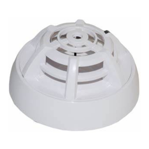
VG-6647 Multi-sense Detector is fully comply with EN54-5&EN54-7. It is contains an optical smoke sensor and
thermistor temperature sensor. The smoke sensor and heat sensor are in two independent fire detection systems but
occupies only one address point. With the pleasing appearance, it is easy to install and maintain.
Technical data
Operating Voltage:
16-28V(Modulated-pulse)
Standby Current:
≤0.5mA
Alarm Current:
≤1.0 mA
Wiring
Two-wire(non-polarized)
Heat Detector Classification
A1R/A2
Temperature range:
-10℃~50℃
Humidity:
≤95%RH, (40±2℃)No condensation
LED Alarm Indication:
Red light emitting
LED Polling Indication:
Red light flashing
IP Rating:
32
Installation
Dimensions:Showing on Fig.1
Fig.1Dimensions
Common Base
VG-6617
Detector
VG-6647
V1.05
VG-6647 Digital Multi-sense Detector
Installation and Operation Manual V1.05
Mounting:
Warning: Please disconnect the loop power in order to avoid control panel broken by short
circuit when mounting Common Base.
Detector Head Mounting showing in Fig.2
Fig.2 Mounting
Mounting Step
1. Install the Common Base into Back Box by using screw. (Back box is standard 86H50 box), Make sure the
Common Base installed stable.
2. Connect the loop to Common Base Terminal 1, 2.
3. Inastall the detector head on to Common Base and directAlignment Mark to Mounting Mark at same time.
4. Turn Alignment Mark aim to Locking Mark finishes the installation.
Wiring Details
1. Wiring Requirement: RVS-2*1.0 mm2 or1.5 mm2 wire for BUS, laid through metal tube (cable sink) or PVC tube.
2.1,2 Should connecting with fire alarm system detection loop (Non-polarized)
3.Loop wiring is shown in Fig.3
Fig.3.Loop wiring
Address setting
1. VG-6537Digital Programmer is used to write an address of the Detector.ConnectingProgarmmer with loop
terminals:1,2 of the Detector before it installation.
2.Set address, Pressing Write key, the address will be shown on the numeric display if successful. It is fail if there
is no address. Please refer to VG-6537 Digital Programmer Manual for details.
2
Back Box
Alignment Mark
Mounting Mark
Locking Mark
L+
L-
Loop (Non-polarized)
3 V1.05
VG-6647 Digital Multi-sense Detector
Installation and Operation Manual V1.05
3.Address range should be within 0-255. The address is unique in a loop.
Sensor setting
VG-6647 has two temperature response modes and one smoke sensitivity mode. The temperature modes are
A1R &A2 and the smoke sensitivity is set at one default setting, which is equivalent to our VG-6627 Smoke
detector Mode 2: 0.126 dB/m. The details of temperature modes please see the following table.
Temp.
Mode
Class
Application Temperature
Static Response Temperature
Typical
Maximum
Min
Max
1
A1R
25
50
54
65
2
A2
25
50
54
70
Mode 1 is Factory Setting.
The letter “R”suffix means that the heat responseclass incorporates a rate-of-rise characteristic. It will give
rapid response even when high rates of rise of air temperature starting at air temperaturessubstantially
below the typical application temperature.
The sensor response mode of VG-6647 can be set by Control Panel, please refer to the corresponding
manual for details.
Testing
Warning:Power is switched off before all devices are installed completely.
The detector must be tested after installation or regular maintenance.
Registration:The fire alarm control panel will registers the detector on line to check if the address of the
detectors mounted is the same address as that registered in the control panel.
Firecondition: After registration, make detector under fire conditions by using hot air generator and/or
Smoke generatorto test whether the detector alarms normally and control panel displays its registered
address.
Reset:After testing, reset the detector through control panel.
Fault Finding
Detector Fault on
Control Panel
Check wiring of Common base, no water no short-circuits and open circuit.
Check the connection between detector and common base.
Nuisance alarm
The detector alarm frequently but there is no Fire and other unusual, then check whether
the chamber in the detector is too dirty and needs to be cleaned
Otherwise, the circuit may be broken.
Address Fault
Address is set incorrectly, Reset by VG-6537 Digital Programmer.
4 V1.05
VG-6647 Digital Multi-sense Detector
Installation and Operation Manual V1.05
Cautions
Dust cover on the detector shouldn’t be removed between installation and acceptance test
toavoidcontamination.
If the detector gives fault warning after a long operation, first check if the chamber in detector are too dirty, or
the position is changed. At last, other faults should be considered.
Fire alarm test requirement as specified in the applicable local codes, we suggest to test every 6 months.
Please put on the dust cover if the room is decorated or wall-painted to avoid contamination.
Limited Warranty
We warrants that the product will be free of charge for repairing or replacing from defects in design, materials and
workmanship during the warranty period. This warranty doesn’t cover any product that is found to have been
improperly installed or used in any way not in accordance with the instructions supplied with the product. Anybody,
including the agents, distributors or employees, is not in the position to amend the contents of this warranty.
Please contact your local distributor for products not covered by this warranty.
Company: V-GREAT GLOBAL CORPORATION
Add.: Second Floor, Capital City, Independence Avenue,
P.O. Box 1008, Victoria, Mahe, Seychelles
Web:http://www.vgreatglobal.com Email: [email protected]om

Other V-GREAT Security Sensor manuals

V-GREAT VG-6617 User manual

V-GREAT

V-GREAT VG-6617 User manual

V-GREAT VG-6637 User manual

V-GREAT

V-GREAT VG-6637 User manual

V-GREAT VG-6727 User manual

V-GREAT

V-GREAT VG-6727 User manual

V-GREAT VG-6627 Operating and installation instructions

V-GREAT

V-GREAT VG-6627 Operating and installation instructions

V-GREAT VG-6633 User manual

V-GREAT

V-GREAT VG-6633 User manual

V-GREAT VG-6611S User manual

V-GREAT

V-GREAT VG-6611S User manual

Popular Security Sensor manuals by other brands

Waters 3100 Operator's guide

Waters

Waters 3100 Operator's guide

Reed Instruments R9200 instruction manual

Reed Instruments

Reed Instruments R9200 instruction manual

Bircher Reglomat EasyMotion operating instructions

Bircher Reglomat

Bircher Reglomat EasyMotion operating instructions

Argus Security Taurus TW-DO-01/916 manual

Argus Security

Argus Security Taurus TW-DO-01/916 manual

Baumer URDK 10P8914/S35A quick start guide

Baumer

Baumer URDK 10P8914/S35A quick start guide

Powerfix Profi 271367 Operation and safety notes

Powerfix Profi

Powerfix Profi 271367 Operation and safety notes

Lince JOLLY Programming and operating manual

Lince

Lince JOLLY Programming and operating manual

Powerfix Profi PMDL 5 B1 operating instructions

Powerfix Profi

Powerfix Profi PMDL 5 B1 operating instructions

GeoMax EZiSYSTEM i Series user manual

GeoMax

GeoMax EZiSYSTEM i Series user manual

VOLTCRAFT LSG-10 operating instructions

VOLTCRAFT

VOLTCRAFT LSG-10 operating instructions

netvox RA0708 user manual

netvox

netvox RA0708 user manual

Leica DIGICAT 500i quick start

Leica

Leica DIGICAT 500i quick start

LEGRAND Tynetec ZXT424 manual

LEGRAND

LEGRAND Tynetec ZXT424 manual

DANLERS CEFPLL10VDC Installation notes

DANLERS

DANLERS CEFPLL10VDC Installation notes

Afriso EURO-INDEX OWWG 3 operating instructions

Afriso EURO-INDEX

Afriso EURO-INDEX OWWG 3 operating instructions

C-LOGIC 520-PC instruction manual

C-LOGIC

C-LOGIC 520-PC instruction manual

Gas Clip Technologies Multi Gas Clip Infrared quick start guide

Gas Clip Technologies

Gas Clip Technologies Multi Gas Clip Infrared quick start guide

Conrad HZK202 operating instructions

Conrad

Conrad HZK202 operating instructions

manuals.online logo
manuals.online logoBrands
  • About & Mission
  • Contact us
  • Privacy Policy
  • Terms and Conditions

Copyright 2025 Manuals.Online. All Rights Reserved.