MPS R03S User manual
Drain Valve
1/4” FNPT
Model Number R03S
Bootstrap Compressor • Installation and Operating Instructions
Midwest Pressure Systems, Inc.
RAV Rev. 0
MPS
M I DW E ST
PRESSURE
SY S T E M S
MPS
M I D W E S T
PRESSURE
S YS T E M S
MPS
M I D W E ST
PRESSURE
SYS T E M S
MPS
M I D W E S T
PRESSURE
SY S T E M S
MPS
M ID W E S T
PR ESSURE
S YS T E MS
MPS
M I D W E S T
PRESSURE
SYS T E M S
MPS Logos
12/5/91
1/2" Square
3/4" Square
1" Square
1-1/4" Square
1-1/2" Square
2" Square
MPS
M ID W E S T
PR ESSURE
S YS T E MS
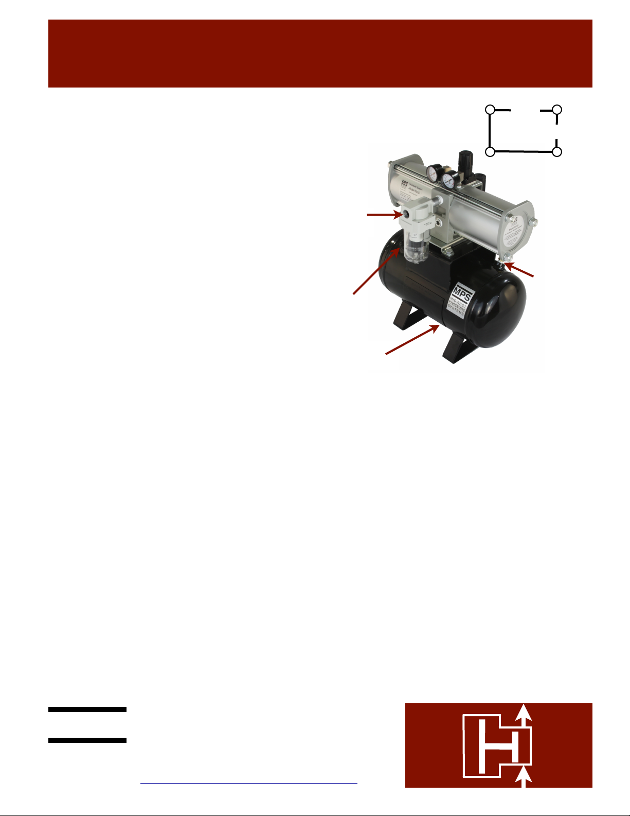
Mount the Model R03S Bootstrap Compressor on a horizontal
surface. Other mounting orientations are not recommended.
The booster system vibrates while operating, so use the four 1/2”
mounting holes, shown in the diagram to the right, to bolt it to a
solid surface.
1
Connect your shop air line to the 1/2” FNPT air inlet filter on the
front of the booster. A shutoff valve can be installed upstream of
the filter for convenient removal of the system for maintenance.
The booster has a built-in discharge pressure regulator. Do not
install a supply pressure regulator. Lowering the supply pressure
reduces the efficiency of the system. The unit is permanently
lubricated. Use of an inlet lubricator will void the
warranty. The maximum inlet pressure is 150 psig.
2
Attach discharge line to the 1/2” FNPT port on the left side of
the receiver tank. If the application requires a
lubricator, make sure the lubricator is installed
downstream of the booster. A filter should be installed to
protect downstream components from seal/booster wear
particles.
3
The discharge pressure regulator is set by the black, snap-
lock knob mounted on the top of the unit. Pull up on the knob
to unlock it. Adjust the knob by turning it clockwise for a
higher discharge pressure (up to a maximum of 230 psig), or
counterclockwise for a lower discharge pressure. Inlet
pressure is read on the gauge closest to the inlet connection.
The second gauge indicates discharge pressure. Supply shop
air to the booster and it will start to operate. Set the regulator
to attain the desired discharge pressure, and push down on
the regulator knob until it “clicks” to lock the regulator on
that setting. The regulator is self-relieving. When the
discharge pressure setting on the regulator is reduced, the
higher pressure stored in the system will vent through the
regulator until pressure equilibrium is reached. If the inlet
pressure is higher than 115 psig, it is possible to
set the regulator so the booster exceeds the
maximum discharge pressure of 230 psig. Do not
operate the booster under these conditions. It is
designed to operate continuously at a maximum
discharge pressure of 230 psig.
5
The Bootstrap Compressor will operate as long as there is
demand for high pressure air. When there is no demand, the
booster will “stall” at the pressure set by the discharge regulator.
The stalled condition consumes no energy and does not damage
the booster. The booster will start up automatically when the
pressure falls slightly as a result of demand for high pressure air.
7
Mounting Bolt Pattern:
7.5”
6.5”
Inlet port
1/2” FNPT
Discharge port
1/2” FNPT
The accumulator tank has a 1/4” ball valve to drain condensate. A
drain line or automatic drain valve can be attached to this valve
when needed. Close the valve before starting booster.
4
The accumulator is rated for 350 psig and includes a relief valve
set for 235 psig. This relief valve was selected to prevent
operation of the booster above its maximum
allowable discharge pressure of 230 psig.
8
For more precise booster control, set the discharge regulator for
a higher pressure than required, and install a filter and secondary
regulator on the discharge line of the accumulator. This allows
for greater accumulator storage capacity, and minimizes pressure
fluctuations in the system. For maximum high pressure air
storage, Bootstrap Compressors are set to charge the
accumulator to 230 psig, and the secondary regulator in the
discharge line of the accumulator is set at the desired, lower
pressure. Make sure that any downstream components are rated
for the accumulator pressure, or are protected by a relief valve in
case the secondary regulator fails.
6
235 psig
Pressure
Relief
Valve
Midwest Pressure Systems, Inc.
850 Transport Drive, Valparaiso, IN 46383
Phone 219-462-0070 Fax 219-318-2277
www.midwestpressuresystems.com
Model Number R03S
Bootstrap Compressor • Operation and Warranty
Midwest Pressure Systems, Inc.
RAV Rev. 0
MPS
M I DW E ST
PRESSURE
SY S T E M S
MPS
M I D W E S T
PRESSURE
S YS T E M S
MPS
M I D W E ST
PRESSURE
SYS T E M S
MPS
M I D W E S T
PRESSURE
SY S T E M S
MPS
M ID W E S T
PR ESSURE
S YS T E MS
MPS
M I D W E S T
PRESSURE
SYS T E M S
MPS Logos
12/5/91
1/2" Square
3/4" Square
1" Square
1-1/4" Square
1-1/2" Square
2" Square
MPS
M ID W E S T
PR ESSURE
S YS T E MS
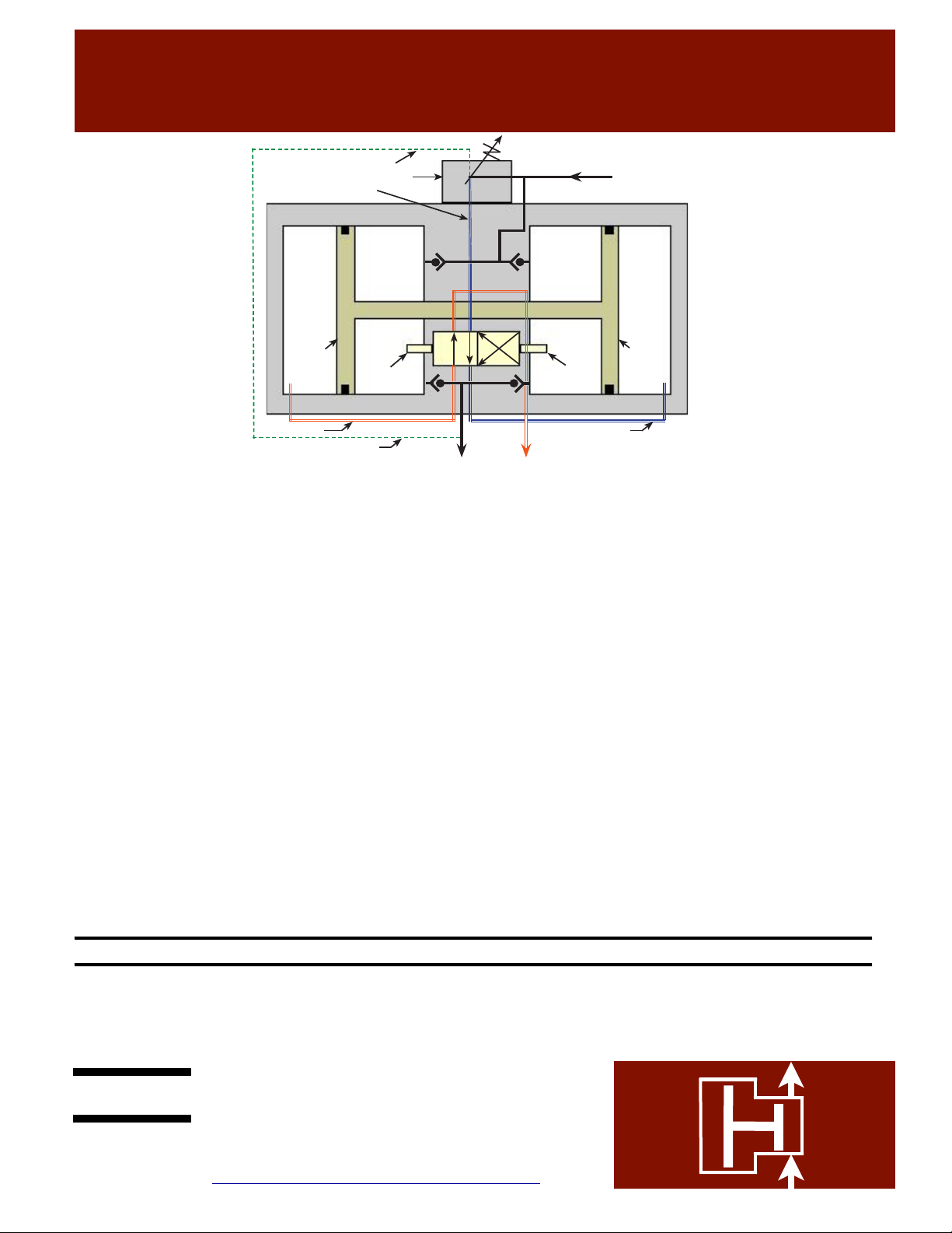
Compression
Chamber A1
Compression
Chamber A2 Drive
Chamber
B2
Drive
Chamber
B1
Piston 1 Piston 2
4-way
Valve
Switch
4-way
Valve
Switch
Pilot Signal to regulator
Built-in discharge regulator
Regulated drive air
Plant air
Exhaust air
Pilot signal to regulator
High pressure air Exhaust air
Regulated drive air
Please refer to the operating description on the right, and the
schematic above to gain an understanding of the design principles
and mechanical function of the R03S Model Bootstrap Compressor.
The moving parts of the Bootstrap Compressor are permanently
lubricated with a multipurpose grease (except for the check valves).
Operation with a lubricator upstream voids the warranty. If a
lubricator is required, it should be installed on the downstream
(discharge) side. A well-maintained 5 micron inlet air filter is
required to maintain the warranty by ensuring that no dust particles
enter the unit and foul the seals, or cause premature wear of the
highly-polished seal surfaces. The wear parts in the booster consist
of check valves, springs and dynamic seals. These parts are
designed for 1800 miles of piston travel. The four-way valve, which
controls movement of the pistons, is a lapped, stainless steel valve
with no elastomeric seals subject to wear. Under normal conditions,
this valve will provide many years of operation. The discharge
regulator built into the center of the unit sees very little wear, and is
designed to provide many years of service under normal conditions.
The wear parts are typically replaced 2 to 3 times before a valve or
regulator kit is required.
#KRW • Wear parts kit
#KRV • Valve kit
#KRR • Regulator kit
The plant air stream always fills Compression Chambers A1 and A2
directly, through a set of check valves. These two chambers are
always pressurized to the maximum initial air pressure available
(the R03S Model Bootstrap Compressor is not designed for inlet air
pressures higher than 150 psig). A branch of the plant air stream
flows through a pilot-activated regulator, which reduces the pressure
to the level required to attain the desired Bootstrap Compressor
discharge pressure (the discharge pressure is set manually by
adjusting the regulator handle). This regulated air stream flows
through a four-way valve which directs it to Drive Chamber B2. At
the same time, the four-way valve opens Drive Chamber B1 to
exhaust. The pressure force exerted on the interconnected pistons by
the pressures in Drive Chamber B2 and Compression Chamber A1,
is sufficient to compress the air in Chamber A2 to a higher pressure
(the maximum discharge pressure attainable is two times the plant
air pressure). At the end of its travel, Piston 2 switches the four way
valve, which opens Drive Chamber B2 to exhaust, and pressurizes
Drive Chamber B1 with regulated drive air, thus reversing the
direction of the interconnected pistons, until Piston 1 switches the
valve back to its original position. The interconnected pistons
shuttle back and forth continuously, producing a high pressure air
stream, determined by the discharge pressure set on the built-in
regulator. The R03S Model is designed to operate at a maximum
discharge pressure of 230 psig. Higher discharge pressures, though
possible, can result in catastrophic failure of the booster.
Operating Description
General Concerns
Midwest Pressure Systems, Inc. warrants the R03S Model Bootstrap Compressor to be free of defects in material and workmanship for
a period of one year after purchase, except piston seals, rod seals, and check valves which are warranted for six months after purchase.
We will either repair or replace a failed unit returned by the customer. No other warranty is expressed or implied. Proof of the purchase
date is required. This warranty does not apply to equipment which has been abused, and is voided by use of a lubricator, or failure to
use a well-maintained inlet filter. Customer must obtain a return authorization number before shipping the unit to the factory.
WARRANTY
Midwest Pressure Systems, Inc.
850 Transport Drive, Valparaiso, IN 46383
Phone 219-462-0070 Fax 219-318-2277
www.midwestpressuresystems.com
Other MPS Air Compressor manuals


Popular Air Compressor manuals by other brands


BE
BE AC3220B user manual

Schneider Airsystems
Schneider Airsystems UNM STS 1000-10-270 XDK operating manual

King Canada
King Canada 8469 Service manual

Quincy Compressor
Quincy Compressor QED 650 Instruction book

Cooper Turbocompressor
Cooper Turbocompressor Turbo Air 3000 Handbook

Craftsman
Craftsman 919.167782 owner's manual

Precision Medical
Precision Medical PM15F user manual

Mangar
Mangar Airflo Mk3 User instructions and warranty

Craftsman
Craftsman 921.166420 owner's manual

DeVillbiss Air Power Company
DeVillbiss Air Power Company D26368 Operator's manual

GEA Bock
GEA Bock EX-HG44e Series Assembly instructions

Porter-Cable
Porter-Cable PXCMLC1683066 instruction manual