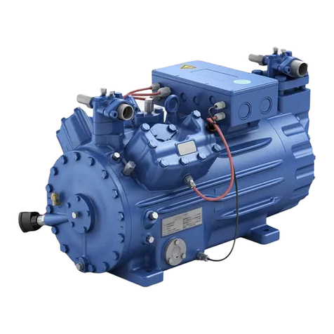
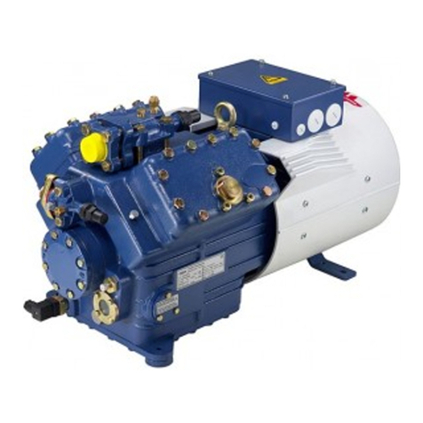
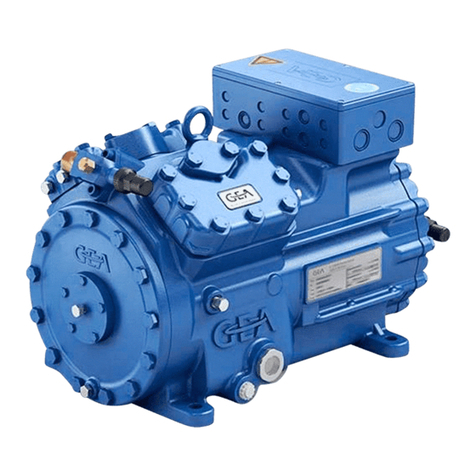
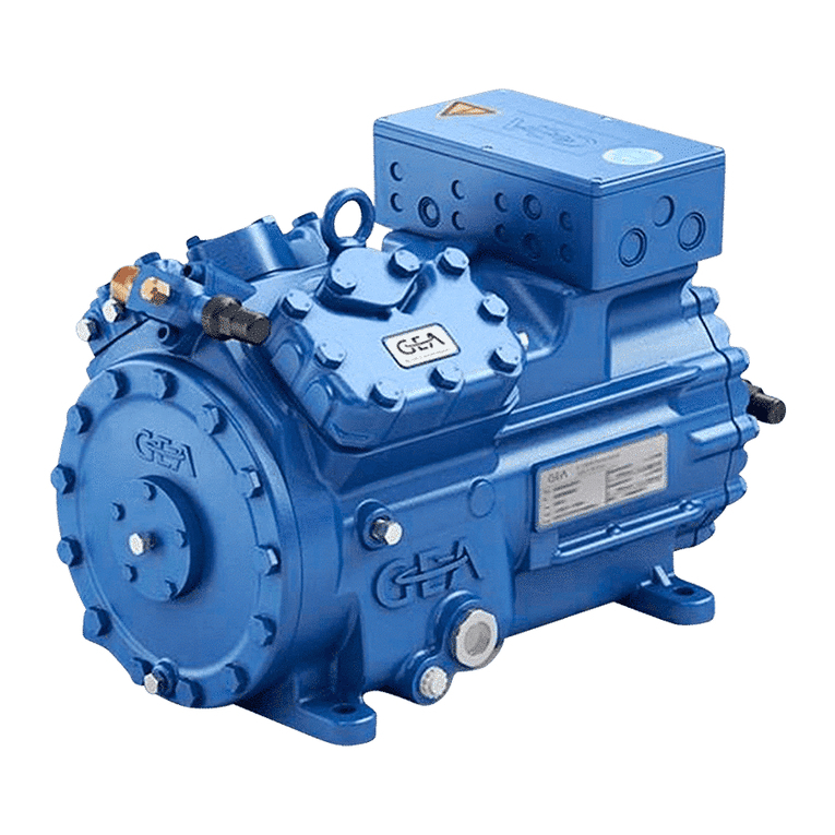
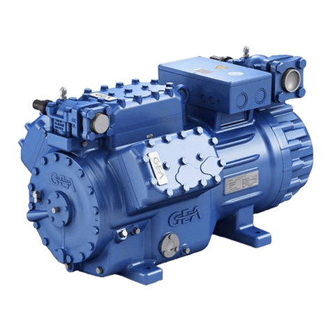
GEA Bock EX-HG44e Series User manual

GEA Bock EX-HG44e/EX-HG56e
Assembly instructions
96389-08.2019-Gb
Translation of the original instructions
Device category 2 G
acc. to directive 2014/34/EU
EX-HG(X)44e/475-4 EX-HG(X)56e/850-4 EX-HG44e/475-4 HC EX-HG56e/850-4 HC
EX-HG(X)44e/565-4 EX-HG(X)56e/995-4 EX-HG44e/565-4 HC EX-HG56e/995-4 HC
EX-HG(X)44e/665-4 EX-HG(X)56e/1155-4 EX-HG44e/665-4 HC EX-HG56e/1155-4 HC
EX-HG(X)44e/770-4 EX-HG44e/770-4 HC
EX-HG(X)44e/475-4 S EX-HG(X)56e/850-4 S EX-HG44e/475-4 S HC EX-HG56e/850-4 S HC
EX-HG(X)44e/565-4 S EX-HG(X)56e/995-4 S EX-HG44e/565-4 S HC EX-HG56e/995-4 S HC
EX-HG(X)44e/665-4 S EX-HG(X)56e/1155-4 S EX-HG44e/665-4 S HC EX-HG56e/1155-4 S HC
EX-HG(X)44e/770-4 S EX-HG44e/770-4 S HC

2
D
GB
F
E
I
96389-08.2019-DGbFEIRu
1 Safety 4
1.1 Identicationofsafetyinstructions
1.2 Qualicationsrequiredofpersonnel
1.3 Safetyinstructions
1.4 Intendeduse
2 Product description 7
2.1 Shortdescription
2.2 Ignitionprotectionconcept
2.3 Nameplate
2.4 Typekey
2.5 ATEX
identication/IECExidentication
3 Areas of application 13
3.1 Approvedrefrigerant
3.2 Importantinformationontheuseofhydrocarbons
3.3 Oilcharge
3.4 Limitsofapplication
Contents Page
About these instructions
Readtheseinstructionsbeforeassemblyandbeforeusingthecompressor.Thiswillavoidmisunder-
standings andpreventdamage.Improperassemblyanduseofthecompressorcanresultinserious
orfatalinjury.
Observethesafetyinstructionscontainedintheseinstructions.
These instructions must be passed onto the end customer along with the unit in which the
compressor is installed.
GEABockGmbH
72636Frickenhausen
Manufacturer
Contact
GEABockGmbH
Benzstraße7
72636Frickenhausen
Germany
Phone+4970229454-0
Fax+4970229454-137
www.gea.com

D
GB
F
E
I
3
96389-08.2019-DGbFEIRu
Contents Page
4Compressor assembly 16
4.1 Ignitionsourcecontrolofthecompressor
4.2 Storageandtransport
4.3 Settingup
4.4 Pipeconnections
4.5 Pipes
4.6 Layingsuctionandpressurelines
4.7 Operatingtheshut-offvalves
4.8 Operatingmodeofthelockableserviceconnections
4.9 Suctionpipelter
5
Electrical connection 20
5.1 Potentialequalization
5.2 Informationforcontactorandmotorcontactorselection
5.3 Terminalcrosssectionforleads
5.4 Connectionofthedrivemotor
5.5-5.7Circuitdiagrams
5.8
ElectronictriggerunitINT69GEx
5.9 ConnectionoftheelectronictriggerunitINT69GEx
5.10FunctionaltestoftheelectronictriggerunitINT69GEx
5.11 ToverifytheintrinsicsafetyofthePTChotgassensor
6 Commissioning 33
6.1 Preparationsforstart-up
6.2 Pressurestrengthtest
6.3 Leaktest
6.4 Evacuation
6.5 Refrigerantcharge
6.6 Start-up
6.7 Avoidingliquidsluggings
6.8 Preventingicingonthecompressor
7 Maintenance 36
7.1 Preparation
7.2 Worktobecarriedout
7.3 Sparepartrecommendation
7.4 Screwconnections
7.5 Decommissioning
8 Accessories 38
8.1 Capacityregulation
8.2 Oilsumpheater
8.3 OildifferentialpressuresensorINT250Ex
9
Technical data 41
10 Dimensions and connections 43
EU Type Examination Certicate 47
IECEx Certicate of Conformity 50
Service 54

4
D
GB
F
E
I
96389-08.2019-DGbFEIRu
1|Safety
1.2 Qualications required of personnel
DANGER Indicates a dangerous situation which, if not avoided,
will cause immediate fatal or serious injury.
WARNING Indicates a dangerous situation which, if not avoided,
may cause fatal or serious injury.
CAUTION Indicates a dangerous situation which, if not avoided,
may cause fairly severe or minor injury.
ATTENTION Indicates a situation which, if not avoided,
may cause property damage.
INFO Important information or tips on simplifying work.
WARNING Inadequately qualied personnel poses the risk of accidents, the
consequence being serious or fatal injury. Work on compressors
must therefore only be performed by personnel with hereinafter
qualications and appropriate to additional qualication according
to EN 60079-14.
•For example, a refrigeration technician, refrigeration mechatronic
engineer.Aswellasprofessionswithcomparabletraining,whichena-
blespersonneltoassemble,install,maintainandrepairrefrigeration
andair-conditioningsystems.Personnelmustbecapableofassessing
theworktobecarriedoutandrecognisinganypotentialdangers.
1.1 Identication of safety instructions:

D
GB
F
E
I
5
96389-08.2019-DGbFEIRu
1.3 Safety instructions
1|Safety
TheGEArefrigeratingcompressorsnamedinthetitleareintendedforinstallationinmachinesthat
weresetupinareasfallingundertheEUExplosionProtectionDirective1999/92/EC(operatordirec-
tive).IntheEuropeanUnion,electricalaswellasmechanicaldevicesoperatedinexplosiveatmos-
pheresmustfulfilwhatareknownasATEX (ATmospheresEXplosibles)conditions.
Thecompressorsarespeciallydesignedforthecategoryshownonthenameplateinaccordancewith
theATEXdirectiveandmayonlybeusedinconformitywiththeconditionsspecifiedanddocumented
intheset-uparea(explosionprotectiondocument).Usersafetyistakenintoaccountasaparticular
focusofdesign.Butitispermissibletostartupthecompressoronlyifitwasinstalledinaccordance
withtheseinstructionsandtheentiresystemintowhichitisintegratedhasbeeninspectedinaccor-
dancewithlegalregulationsandapproved.
ThedeclarationsandremarksbyGEAcanonlyrefertotheproductitself.Weassumethattheappli-
cableregulations,standardsandtechnicalrulesarefollowedininstallationandduringoperation.The
plantconstructor/operatormustevaluatetheinteractionswithotherdevicesandcomponentsofthe
systemandwiththeenvironment,especiallyregardingpotentialignitionsources.
WARNING • Refrigerating compressors are pressurised machines and there-
fore require particular caution and care in handling.
• Risk of burns! Depending on the operating conditions, surface
temperatures of over 60 °C on the pressure side or below 0 °C on
the suction side can be reached.
• The maximum permissible overpressure must not be exceeded,
even for testing purposes.
• The compressor may be operated only if it is free of defects!
• No work may be performed when an explosive atmosphere is
present!
• Smoking, re and open ame are strictly prohibited! Mobile tele-
phones must be switched off!
• Strongly charge-generating processes must be excluded within
2 meters. The contact of rapidly moving particles with the sur-
face of the compressor must be avoided with certainty (e.g.
pneumatically moved dust, owing uids, direct ventilation, belt
drives, brushes, foils, etc.).
• Perform installation work only if no damage, leaks and/or
appearances of corrosion can be recognized.
6
D
GB
F
E
I
96389-08.2019-DGbFEIRu
1|Safety
TheseassemblyinstructionsdescribethecompressorsnamedinthetitlemanufacturedbyGEA.The
compressorisintendedforuseinrefrigerationsystemsinsideexplosion-endangeredareasunder
thedesignationspeciedonthenameplateinaccordancewiththeEuropeanATEX Directives.
Useofthespeciedrefrigerantsaswellasobservanceoftheoperatinglimitsandlistedstandards
mustbeensuredinanycase.Likewise,allaccessoriesavailablefrom,approvedandspeciallymarked
byGEAareexclusivelyapproved,accordingtotheirintendeduse,forattachmenttoandoperation
withGEAcompressorsofappliancecategory2inaccordancewithDirective2014/34/EU.
1.4 Intended use
WARNING Any other use of the compressor and its approved accessories is
prohibited! The ATEX permit is voided if the compressor is used
outside the operating limits or undergoes inadmissible design
changes!

D
GB
F
E
I
7
96389-08.2019-DGbFEIRu
2|Product description
Fig. 1
2.1 Short description
Fig. 2
Oilsightglass
Valveplate
Cylindercover
Discharge
shut-offvalve
Oilpump
Terminalbox
Suction
shut-offvalve
Drivesection
Motorsection
DimensionandconnectionvaluescanbefoundinChapter10
Transporteyelet
Potential
equalization
• EX-HG44e:Semi-hemeticfour-cylinderreciprocatingcompressorwithoilpumplubrication.
• EX-HG56e:Semi-hemeticsix-cylinderreciprocatingcompressorwithoilpumplubrication.
• Foruseinexplosion-endangeredareas.
EX-HG44e
EX-HG56e
Nameplate

8
D
GB
F
E
I
96389-08.2019-DGbFEIRu
2|Product description
2.2 Ignition protection concept
In accordance with Directive 2014/34/EU, GEA ATEX compressors are suitable for use in device
category2forexplosivegasatmospheresuptotemperatureclassT3andexplosionhazardsubgroup
IIB/IIC.
Theentirecompressor,includingmotor,isperceivedastechnicallytightandthereforedoesnotneed
anignitionprotection.
Topreventignitionriskcausedbyworkingmaterialsalsoduringsystemmalfunctions,allusedwork-
ingmaterialshavetomeettherequirementsforthetemperatureclassofthecompressor.Thesurface
temperature of the compressor may not exceed 80 % of the ignition temperature of the working
material.Forthisreasonallworkingmaterialsneedtohaveanauto-ignitiontemperatureof>250°C.
Toprotectagainsthightemperaturesthatmayoccurduringincorrectoperationorfaultsatthecom-
pressor, the areas with the highest heat potential are controlled with temperature sensors (Ex b).
The installation of the electronic control unit INT69 EX2 and the safety barrier,
bothincludedinthescopeofsupply,isthereforeabsolutelynecessary.
Theconnectionareasforloadcircuitsaredesignedaccordingtotherequirementsoftheappliance
categoryinExe.ThecircuitsforthetemperaturesensorsoftheusedignitionsourcecontrolExbhave
tobeintrinsicallysafetopreventinadmissiblyhighthermalorelectricvalues.Toensuretheintrinsic
safety,theincludedsafetybarrierhastoadditionallybeintegratedintheelectriccircuitaccordingto
thisassemblyinstruction.TheterminalboardisdesignedfortheprotectiontypeExde.Thewhole
electricconnectionareaisprotectedbyahousingthatcomplieswiththerequirementsfortheprotec-
tiontypeincreasedsafety(Exe).
Thescopeofdeliveryofthestandardcompressorcomprisesaconductivepaintnish,thatissuitable
fortheuseinexplosiongroupIIC.Ifthecompressorisdeliveredwiththeaccessory"OffshorePaint
Finish",theapplicationisrestrictedtoexplosiongroupIIB.

D
GB
F
E
I
9
96389-08.2019-DGbFEIRu
2|Product description
Accessories
Heatingelementsforthecompressorstoprotectagainstexplosionrisksaredesignedintheprotection
typesincreased safety(Exd) andhave tohave tobemounted stationary atthe designatedareas
in the compressor housing.The heating elements can be operated without temperature- and oil
levelcontrolsincethethermaltypetestingbythemanufacturerveriedthattheheatingelements
preventthe exceedingofthe temperatureclassof thecompressor.The controlhasto becarried
out in a way that the heating element can only be operated during shutdown of the compressor.
Themagneticcoilofthecapacityregulatorisdesignedintheprotectiontypeencapsulation(Exm)to
protectagainstexplosionrisks.Inaddition,theconnectingareasofthecoilareplacedinahousing
thatcomplieswiththerequirementsoftheprotectiontypeincreasedsafety(Exe).
TheoildifferentialpressuresensorINT250ExfromKriwanisexecutedasasimpleelectricaloperating
devicewithoutarecognisedignitionprotectiontype.Toensurereliableoperation,however,itmustbe
equippedasanintrinsicallysafeelectricalcircuitwithswitchingrepeater.Pleasenotethattheplastic
housingoftheINT250Excanbeelectricallychargedbymeansofcharge-generatingprocesses(e.g.
cleaningwithadrycloth,directadditionalventilationviafanetc.).Accordingly,theoperatorisrequired
totakemeasuressothatignitionhazardscanbereliablyruledout.
Equipment Typeofignitionprotection
Terminalbox Exe
Terminalboard Exd+e
Throughterminalsintheterminalbox Exe
Cable/lineentrances/plug Exd/e
Magneticcoil Exemb
Oilsumpheater Exd
OildifferentialpressuresensorINT250Ex Exi
HotgasPTCsensor Exi

10
D
GB
F
E
I
96389-08.2019-DGbFEIRu
GGEA Bock GmbH
I 72636 Fricken hausen, Germany
@II 2G Ex de ia mb IIC T3 Gb/ EPS 17 ATEX 1002X
Ex de ia mb I I C T 3 G b / I E C E x E P S 17.0001 X (
E
g
1
IP66
2|Product description
/
HG
EX 4770-
-4 SX
2.4 Type key (example)
¹)HG-Hermeticgas-cooled(suctiongas-cooled)
²)X - Esteroilfilling(HFCrefrigerant),e.g.R134a,R404A,R507,R407C)
3)S- Morepowerfulmotor,e.g.air-conditioningapplications
Fig. 3
HC
forhydrocarbons
Motorvariant3)
Numberofpoles
Sweptvolume
e-series
Numberofcylinders
Size
Esteroillling²)
Series ¹)
Ex-design
}
}
1 Typedesignation 6 Voltage,circuit,frequency
2 Machinenumber 7 Nominalrotationspeed
3 maximumoperatingcurrent 8 Displacement
4 Startingcurrent(rotorblocked) 9 Voltage,circuit,frequency
Y:Partwinding1 10 Nominalrotationspeed
YY:Partwindings1and2 11 Displacement
5 ND(LP):max.admissibleoperating 12 Oiltypelledatthefactory
pressur
e(g)Lowpressureside 13 Terminalboxprotectiontype
HD(HP):max.admissibleoperating 14 Permissibleambienttemperature
pressure(g)Highpressureside
Electrical accessories can change
the IP protection class!
Observe the limits of
application diagrams!
50 Hz
60 Hz
1
2
3
4
5
6
7
8
9
10
12
13
11
14
2.3 Name plate (example)
4 e

D
GB
F
E
I
11
96389-08.2019-DGbFEIRu
2|Product description
2.5 ATEX identication / IECEx identication
2G T3 Gb
II ia IIB/IIC
Ex
demb
ExplosiongroupIIforEx-endangered
areas(notundergroundbuildings)
Suitabilityforgas-explosivearea
Devicecategory2(=zone1)
TemperatureclassT3(max.200°C)
Equipmentprotectionlevel
Explosionsubgroups,
IIB=Offshorepaintnish
IIC=ESDpaintnish
Intrinsicallysafeequipment
Increasedsafety
Flameproofenclosure,heater(option)
Europ.explosionprotectionacc.to
Direc.2014/34/EU
Encapsulation,magneticcoil(option)

12
D
GB
F
E
I
96389-08.2019-DGbFEIRu
3|Areas of application
EPS 17 ATEX 1002 X / IECEx EPS 17.0001 X
BureauVeritas
ConsumerProductsServices
GermanyGmbH
Internationalexplosionprotection
Yearoftest/Testreportnumber
Yearoftest
BureauVeritas
ConsumerProductsServices
GermanyGmbH
Specialconditions:
see"ConditionsofCertication"
Specialconditions:
seepoint17oftheECtype
examinationcerticate
Testreportnumber
ATmospheresEXplosibleseuropean
explosionprotection
ATEX approval type IECEx approval type

D
GB
F
E
I
13
96389-08.2019-DGbFEIRu
3|Areas of application
3.2 Important information on the use of hydrocarbons
Hydrocarbons(combustiblerefrigerants)maybeusedinthecompressorsnamedinthetitleonlyifall
relevantandapplicableregulations,standardsandtechnicalrulesarefollowed.Nationalsafetyregu-
lationsmustbeobserved.Inaddition,werefertothefollowingapplicablestandardsandregulations:
EN378,BGR500,TRBS2152,ECDirectives1999/92/ECand2014/34/EU.
The compressor and the refrigeration system must be permanently equipped with clear, identical
labels/plates(ISO3864)thatstatethatcombustiblerefrigerantsareused.Thiswarningplatemustbe
unremovablyattachedtothecompressor.
AhazardanalysisinaccordancewiththeOperationalSafetyOrdinancemustbeperformedforthe
set-uplocation.Useandhandlingoftherefrigerationsystemandcompressoraretobegovernedin
theexplosionprotectiondocument.
Installation,placementintooperation,serviceandrepair(aspermittedbythemanufacturer)mayonly
beperformedbypersonnelwhohavebeenspeciallytrainedoncombustiblerefrigerants.
Ifthecompressorhastoberemovedfromthesystemforinspection/maintenance/repair,theremaining
refrigerantmustbesuctionedoutandthecompressorevacuated,lledwithnitrogen(<0.5bar)and
closedgas-tight.Thecompressormustbeequippedwithatagthatclearlystatesthatthecompressor
wasoperatedwithcombustiblerefrigerant(nametherefrigerant).
Ifthesystemcontainscombustiblerefrigerantsorresidues,extremecautionmustbeexercisedwhen
workingonthecompressorduetothedangerofexplosion.Thisappliesespeciallyfortheuseofre,open
ameorotherignitionsources(e.g.electronicdevices,mobiletelephones,staticcharges,sparks,...).
Duringmaintenanceandrepair,itmustbenotedthathydrocarbonresiduesmayremaindissolvedin
theoil.Inadditionuseddryerscontainbottomsoftheinammablerefrigerants.Flushthedryerwith
nitrogenandsupplyittotherecycling.
Itshouldbenotedthatthesolubilityofhydrocarbonsinoilcanbeveryhigh,especiallyathighsuction
pressures.Ahigh-viscositylubricantmayberequired,dependingontheapplicationandexperience.
ThelubricantmustbereleasedforusebyGEA.Dependingontheapplication,apump-downswitch
shouldalsobeadded(e.g.whentherefrigerationsystemissetupoutside).
3.1 Approved refrigerant
INFO Used refrigerants have to have a self-ignition temperature of
> 250 °C.
• HFKW/HFC: R134a,R404A,R507,R407C
• (H)FCKW/(H)CFC: R22
• Hydrocarbons: R290,R1270

14
D
GB
F
E
I
96389-08.2019-DGbFEIRu
3|Areas of application
Compressorswithesteroillling(FUCHSRenisoTritonSE55)aremarkedwithanXinthetype
designation(e.g.EX-HGX44e/770-4).CompressorswithoilllingFUCHSRenisoSnyth68are
markedwithHC(e.g.EX-HG44e/770-4HC).
Oillevel:Theoillevelfromthefactoryreachestheupperedgeofthesightglass.Theoillevelmust
beregulatedinoperation;ifnecessarytoachieveacorrectoillevel(seeFig.4),oilmayhavetobe
drainedofforadded.
Operate compressors only with the approved refrigerants and the corresponding assigned and
approvedoils.Othercombinations(e.g.R22withesteroils)arenotpermitted!
Conversiontoanotherrefrigerant/oilisnotpermitted!
ATTENTION The oil level must be in the
visible part of the sight glass;
damage to the compressor is
possible if overfilled or under-
filled!
max.
min.
oillevel
Thefollowingoilgradesareapprovedforthecompressor:
3.3 Oil charge
Refrigerant Oilgrade
R22 FUCHSRenisoSP46
R134a,R404A,R507,R407C FUCHSRenisoTritonSE55
R290,R1270 FUCHSRenisoSynth68
INFO Used refrigerant oils have to have a self-ignition temperature of
> 250 °C.
Fig. 4Fig. 4
E X - H G 4 4 e
1.6Ltr.
EX-HG56e
1.4Ltr.
~
~
~
~

D
GB
F
E
I
15
96389-08.2019-DGbFEIRu
3|Areas of application
3.4 Limits of application
ATTENTION Compressor operation is possible within the operating limits.
These can be found in GEA Bock compressor selection tool (VAP)
under vap.gea.com. Observe the information given there.
- Max. permissible discharge end temperature 140 °C.
- Max. permissible switching frequency 12 x / h.
- A minimum running time of 3 min. steady-state condition
(continuous operation) must be achieved.
Suction gas overheating ∆toh:
The correct setting of the suction gas overheating temperature
∆toh at the compressor entrance is of decisive importance:
Too low ∆toh => danger of liquid operation
Too high ∆toh => danger of compressor overheating
∆toh min = 7 - 10 K, individual adjustment required.
Permissible ambient temperature range −20 °C to +60 °C.
Avoid continuous operation near the limits.
For operation with capacity regulator:
-
Continuous operation, when the capacity regulator is activated,
is not permissible and can cause damage to the compressor.
- The suction gas superheat temperature may need to be reduced
or set individually when operating near to the threshold
.
- When the capacity regulator is activated, the gas velocity in the
system can not under certain circumstances ensure that suf-
cient oil is transported back to the compressor.
For operation with frequency converter:
- the maximum current and power consumption may not
be exceeded. During operation above the mains frequency
the application limit can be restricted.
Variable frequency range
: 25 - 70 Hz.
During operation in the vacuum range, there is a danger of air
entering on the suction side. This can cause chemical reactions,
pressure rise in the condenser and an excessive pressure gas tem-
perature as well as shifting of the refrigerant ignition limit into the
critical range. Avoid absolutely any entry of air!

16
D
GB
F
E
I
96389-08.2019-DGbFEIRu
4|Compressor assembly
4.1 Ignition source control of the compressor
To protectagainstanexceeding oftemperaturetheprotectiontypeignitionsourcecontrol"b"is
used at the compressor.Viasensors,theareas with the highest heat potential at every cylinder
coverarecontrolled.Additionally,thetemperatureofthemotorwindingiscontrolledbythesafety
deviceINT69EX2.
Thepermissiblelimittemperaturesfornormaloperationofthecompressorweresetwith130°Cfor
themotorandwith140°Cforthehotgassideofthecylindercover.Ifoneofthosevaluesisexceeded,
thecompressorisshutdownbythecontroldeviceINT69EX2.Besidestheinstallationaccordingto
wiringdiagram,theoperator/installerdoesnothavetoregardotherparametersforthecorrectfunc-
tioningoftheignitionprotectionsystem.Afunctioncheckhoweverhastobecarriedoutbeforeevery
startupofthecompressoraccordingtosection5.10ofthisassemblyinstruction.
ForasafefunctionoftheignitionsourcecontroltheINT69EX2hastobeinstalledaccordingtothe
wiring diagram g. 21. Check the function of the ignition protection system according to section
5.10.Defectivesensorsorignitionprotectionsystemshavetobereplacedbeforereconnectionofthe
compressor.
Operation of the compressor without igintion source control is not permitted!
After shutdown by the INT69 EX2, precise error diagnostics and error correction is necessary.
The INT69 EX2 has a restart interlock that can only be interrupted by means of voltage inter-
ruption.
INFO • New compressors are factory-lled with inert gas. Leave this ser-
vice charge in the compressor for as long as possible and prevent
the ingress of air.
•Check the compressor for transport damage before starting any
work.
•Before starting work, obtain written work release.
•Observe national regulations when setting up explosion-protected
systems (within the EU: ATEX Directive 1999/92/EG, EN 60079-14,
EN 60079-17 a.o.).
• Use only tools permitted for explosion-protected systems (within
the EU, in accordance with EN 1127-1).
• Observe work safety rules (TRGS 727, e.g. protective shoes,
clothing etc.)!

D
GB
F
E
I
17
96389-08.2019-DGbFEIRu
Setuponanevensurfaceorframewithsufcientload-
bearingcapacity.Onlysetuponaslantafterconsulting
withthemanufacturer.
Singlecompressorpreferablyonvibrationdamper.
Provideadequateclearanceformaintenancework.
Ensureadequatecompressorventilation.
Donotoperateinanaggressiveand/orcorrosiveatmosphere.
Fig. 7
Fig. 8
Fig.9
F
E
D
C
B
A
1
2
3
4
F
E
D
C
4
3
2
1
A
B
Tol.-Ang. DIN ISO 2768-mK
Ra Rz
Maß
Passung
Freigabe
Alternativbezug:
Baumustergeprüft
Teil inaktiv
Lieferantenzeichnung
-
-
K.-Auftrag:
PL:
Zeichnung ungültig
Entwicklungsstand
Teil keine Serie
120
400
±0.5
über 0.5
bis 6
Benzstraße 7 - 72636 Frickenhausen - Germany - www.bock.de
-
-
Unbemaßte Radien:
-
Diese Zeichnung ist unser Eigentum!
Sie darf ohne unsere Genehmigung weder nach-
gebildet, vervielfältigt, oder Dritten Personen zu-
gänglich gemacht werden. Der Nachbau nach
dieser Zeichnung, oder an Hand der nach dieser
Zeichnung hergestellten Gegenstände durch den
Abnehmer oder Dritte ist nicht gestattet.
Wir behalten uns alle Rechte, gemäß DIN ISO 16016
an dieser Zeichnung vor.
Bearb.
Datum
Änderungs-Nr.
Werkstoff:
Ausgangsteil, bzw. Rohteil:
--
Gepr.
Name
Datum
19.04.
Werkstückkanten
DIN ISO 13715
Ersatz für:
Ersetzt durch:
Erstellt
2010
Geprüft
-
Kurz
Zone
1/x
Oberflächenbehandlung / Härte:
-
Blatt:
Änderungsbeschreibung
400
Benennung:
±0.8
1000
30
6
-
±0.3
120
30
±0.2
Zeichn.-Nr. Teile-Nr.
Oberflächenangaben ISO 1302
x.xxxx-xxxxx.x
Zust.
Gußtoleranzen:
Gewicht: (kg)
±0.1
Maßstab:
1:1
Wasserwaage
für Indesign
Der Lieferant muß sicherstellen, dass die Ware in
einwandfreiem Zustand angeliefert wird (Korrosions-
schutz, Verpackung für sicheren Transport).
Rz 25
Rz 160
s
25
z
y
x
w
u
t
0,05
Rz 1,6
0,3
0,7
1,6
2
Rz 16
6,3
Rz 63
Rz 6,3
Rz 12,5
F:\user\kurz\3D Sachen\3D Teile\Zeichnungen\Wasserwaage
4|Compressor assembly
Lighteningprotection:Ifthecompressorissetupoutdoors,
alighteningprotectionconcepthastobeintegrated.
Sunprotection:Ifthecompressorissetupoutdoors,ithas
tobeprotectedfromdirectsunlight.
Fig.10
Fig. 11
4.3 Setting up
?
4.2 Storage and transport
Usetransporteyelet.
Donotliftmanually!
Useliftinggear!
Storageat(−30°C)-(+70°C),maximumpermissiblerelativehumi-
dity10%-95%,nocondensation
Donotstoreinacorrosive,dusty,vaporousatmosphereorinacom-
bustibleenvironment.
Fig. 6
Fig. 5
ATTENTION Fittings (e.g. pipe holders, additional units, mounting parts etc.)
on the compressor are not permissible!

18
D
GB
F
E
I
96389-08.2019-DGbFEIRu
4|Compressor assembly
4.5 Pipes
The pressure and suction shut-off valves have graduated inside
diameterssothatpipesinthecommonmillimeterandinchdimensions
canbeused.Thepipewillbeinsertedmoreorlessdeep,dependingon
thedimension.
The connection diameters of the shut-off valves are designed for
maximumcompressorperformance.The actual required pipe cross
section must be matched to the output. The same applies for
non-return valves.
Fig.12:graduated
internaldiameter
4.4 Pipe connections
ATTENTION An explosive atmosphere must not be present!
Do not solder as long as the compressor is under pressure.
Superheating can damage the valve. Remove the pipe supports
therefore from the valve for soldering and accordingly cool the
valve body during and after soldering.
Only solder using inert gas to inhibit oxidation products (scale).
Pipesandsystemcomponentsmustbecleananddryinsideandfreeofscale,swarfandlayersof
rustandphosphate.Onlyuseair-tightparts.
Lay pipes correctly. Suitable vibration compensators must be provided to prevent pipes being
crackedandbrokenbyseverevibrations.
Ensureaproperoilreturn.
Keeppressurelossestoanabsoluteminimum.

D
GB
F
E
I
19
96389-08.2019-DGbFEIRu
Rigid
fixed point
As short
as possible
4|Compressor assembly
4.7 Operating the shut-off valves
Beforeopeningorclosingtheshut-offvalve,releasethevalvespindlesealbyapprox.1/4ofaturn
counter-clockwise.
Afteractivatingtheshut-offvalve,re-tightentheadjustablevalvespindlesealclockwise.
Fig. 14 Fig. 15
Valve spindle seal
Release Tighten
4.6 Laying suction and pressure lines
Fig. 13
A rule of thumb: Alwayslaytherstpipesectionstartingfromtheshut-offvalvedownwards and
parallel to the drive shaft.
ATTENTION Improperly installed pipes can cause cracks and tears which can
result in a loss of refrigerant
INFO Proper layout of the suction and pressure lines directly after the com-
pressor is integral to the smooth running and vibration behaviour of
the system.
a)
a)ForEX-HG44eaintermediateange(height27mm)isoptionalavailable,
Art-Nr.81194.
Withthisintermediateangeitispossibletolaythepressurelinedirectlyfrom
thevalvetotheleftorright.

20
D
GB
F
E
I
96389-08.2019-DGbFEIRu
4|Compressor assembly
DANGER Risk of electric shock! High voltage!
Only carry out work when the electrical system is disconnected
from the power supply!
5 Electrical connection
ATTENTION When attaching accessories with an electrical cable, a minimum
bending radius of 3 x the cable diameter must be maintained for
laying the cable.
Pipeconnection
Pipeconnection
4.8 Operating mode of the lockable service connections
Fig. 16
Opening the shut-off valve:
Spindle:turntotheleft(counter-clockwise)asfarasitwillgo.
—>Shut-offvalvecompletelyopened/serviceconnectionclosed.
Theconnectionwhichcannotbeshutoffisintendedforsafetydevices.
Fig. 17
Opening the service connection
Spindle:Turn1/2-1turntotherightclockwise.
—>Serviceconnectionopened/shut-offvalveopened.
Theconnectionwhichcannotbeshutoffisintendedforsafetydevices.
Serviceconnection
closed
Connection
blocked
Spindle
Connectioncannot
beshutoff
Connectioncannot
beshutoff
Serviceconnection
opened
Spindle Connection
open
Compressor
Compressor
Afteractivatingthespindle,generallytthespindleprotectioncapagainandtightenwith14-16Nm.
Thisservesasasecondsealingfeatureduringoperation.
5| Electrical connection
For systems with long pipes and higher degree of contamination, a lter on the suction-side is
recommended.Thelterhastobebereneweddependingonthedegreeofcontamination(reduced
pressureloss).
4.9 Suction pipe lter
This manual suits for next models
29
Table of contents
Other GEA Bock Air Compressor manuals

GEA Bock
GEA Bock HG12P/75-4 User manual

GEA Bock
GEA Bock HGX44e CO2 Series User manual

GEA Bock
GEA Bock EX-HG66e Series User manual

GEA Bock
GEA Bock Bock HA5 User manual

GEA Bock
GEA Bock IN Touch HAX2/70-4 CO2 T User manual

GEA Bock
GEA Bock HG34e A Series User manual

GEA Bock
GEA Bock In Touch HA4/310-4 User manual

GEA Bock
GEA Bock HG66e Series User manual

GEA Bock
GEA Bock FK30 User manual

GEA Bock
GEA Bock HA22e User manual