Model Number R00S
Bootstrap Compressor • Operation and Warranty
Midwest Pressure Systems, Inc.
RAV Rev. 0
MPS
M I DW E ST
PRESSURE
SY S T E M S
MPS
M I D W E S T
PRESSURE
S YS T E M S
MPS
M I D W E ST
PRESSURE
SYS T E M S
MPS
M I D W E S T
PRESSURE
SY S T E M S
MPS
M ID W E S T
PR ESSURE
S YS T E MS
MPS
M I D W E S T
PRESSURE
SYS T E M S
MPS Logos
12/5/91
1/2" Square
3/4" Square
1" Square
1-1/4" Square
1-1/2" Square
2" Square
MPS
M ID W E S T
PR ESSURE
S YS T E MS
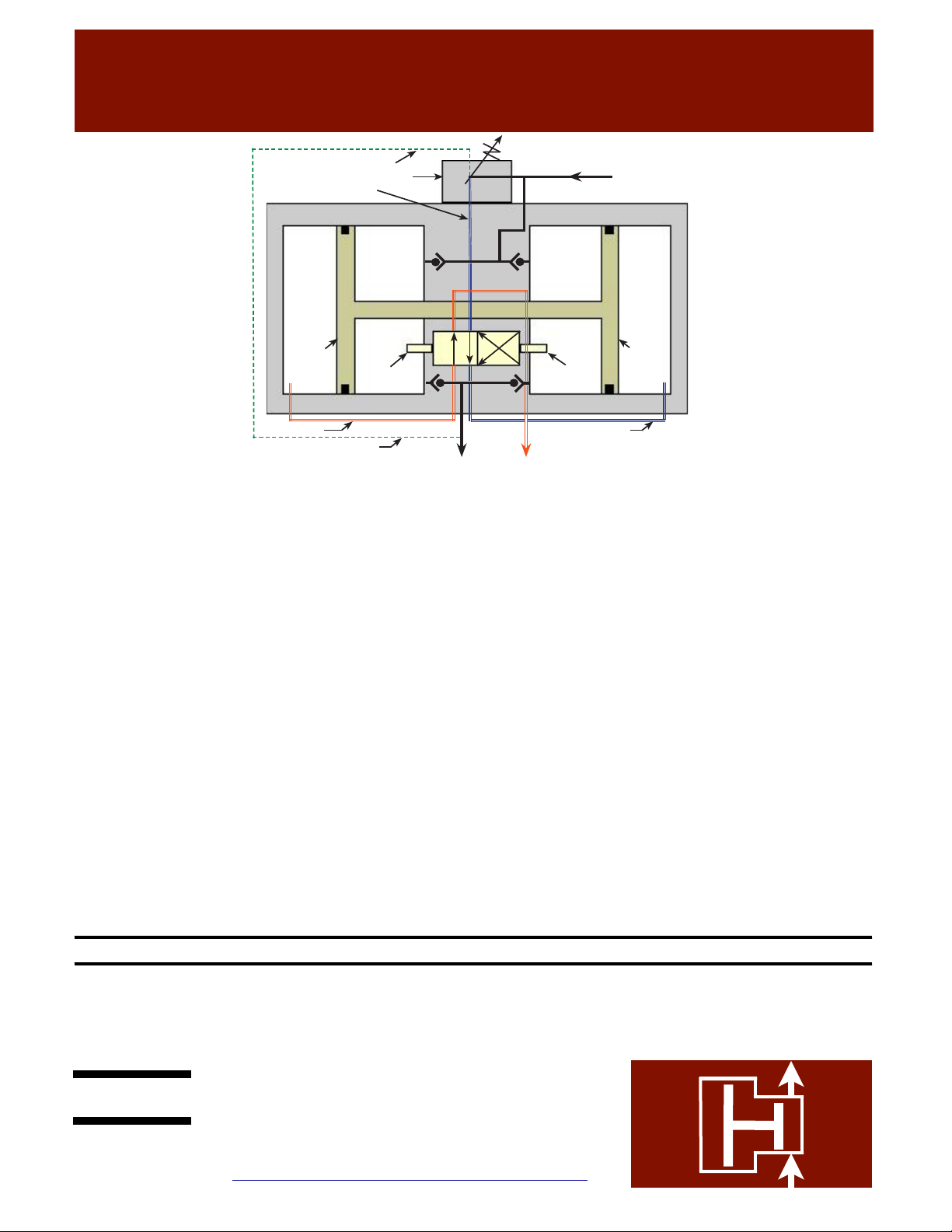
Compression
Chamber A1
Compression
Chamber A2 Drive
Chamber
B2
Drive
Chamber
B1
Piston 1 Piston 2
4-way
Valve
Switch
4-way
Valve
Switch
Pilot Signal to regulator
Built-in discharge regulator
Regulated drive air
Plant air
Exhaust air
Pilot signal to regulator
High pressure air Exhaust air
Regulated drive air
Please refer to the operating description on the right, and the
schematic above to gain an understanding of the design principles
and mechanical function of the R00S Model Bootstrap Compressor.
The moving parts of the Bootstrap Compressor are permanently
lubricated with a multipurpose grease (except for the check valves).
Operation with a lubricator upstream voids the warranty. If a
lubricator is required, it should be installed on the downstream
(discharge) side. A well-maintained 5 micron inlet air filter is
required to maintain the warranty by ensuring that no dust particles
enter the unit and foul the seals, or cause premature wear of the
highly-polished seal surfaces. The wear parts in the booster consist
of check valves, springs and dynamic seals. These parts are
designed for 1800 miles of piston travel. The four-way valve, which
controls movement of the pistons, is a lapped, stainless steel valve
with no elastomeric seals subject to wear. Under normal conditions,
this valve will provide many years of operation. The discharge
regulator built into the center of the unit sees very little wear, and is
designed to provide many years of service under normal conditions.
The wear parts are typically replaced 2 to 3 times before a valve or
regulator kit is required.
#KRW • Wear parts kit
#KRV • Valve kit
#KRR • Regulator kit
The plant air stream always fills Compression Chambers A1 and A2
directly, through a set of check valves. These two chambers are
always pressurized to the maximum initial air pressure available
(the R00S Model Bootstrap Compressor is not designed for inlet air
pressures higher than 150 psig). A branch of the plant air stream
flows through a pilot-activated regulator, which reduces the pressure
to the level required to attain the desired Bootstrap Compressor
discharge pressure (the discharge pressure is set manually by
adjusting the regulator handle). This regulated air stream flows
through a four-way valve which directs it to Drive Chamber B2. At
the same time, the four-way valve opens Drive Chamber B1 to
exhaust. The pressure force exerted on the interconnected pistons by
the pressures in Drive Chamber B2 and Compression Chamber A1,
is sufficient to compress the air in Chamber A2 to a higher pressure
(the maximum discharge pressure attainable is two times the plant
air pressure). At the end of its travel, Piston 2 switches the four way
valve, which opens Drive Chamber B2 to exhaust, and pressurizes
Drive Chamber B1 with regulated drive air, thus reversing the
direction of the interconnected pistons, until Piston 1 switches the
valve back to its original position. The interconnected pistons
shuttle back and forth continuously, producing a high pressure air
stream, determined by the discharge pressure set on the built-in
regulator. The R00S Model is designed to operate at a maximum
discharge pressure of 230 psig. Higher discharge pressures, though
possible, can result in catastrophic failure of the booster.
Midwest Pressure Systems, Inc. warrants the R00S Model Bootstrap Compressor to be free of defects in material and workmanship for
a period of one year after purchase, except piston seals, rod seals, and check valves which are warranted for six months after purchase.
We will either repair or replace a failed unit returned by the customer. No other warranty is expressed or implied. Proof of the purchase
date is required. This warranty does not apply to equipment which has been abused, and is voided by use of a lubricator, or failure to
use a well-maintained inlet filter. Customer must obtain a return authorization number before shipping the unit to the factory.
Midwest Pressure Systems, Inc.
850 Transport Drive, Valparaiso, IN 46383
Phone 219-462-0070
www.midwestpressuresystems.com


