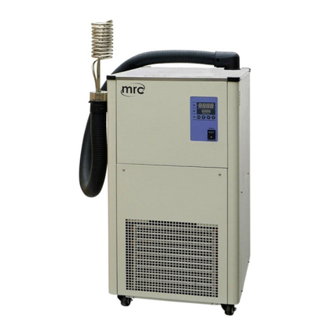
MRC CWN-1.6KW Operation instructions

User Operating Manual
Recirculating Coolers, Chiller
Original Instructions
3, Hagavish st. Israel 58817 Tel: 972 35595252, Fax: 972 3 5594529
MRC. 9.22

Congratulations!
Thanks for choosing our product.
We are confident it will serve you for a long time!
First of all, we thanks for the trust to us. This operating manual has been
designed to help you understanding the principles of operation and possibilities
of chillers. For optimum utilization of all functions, we recommend that study this
manual before operation.

Table of Contents
Section I General Information.................................................................................... 1
1.1 Safety Warnings................................................................................................. 1
1.2 System Introduction........................................................................................... 1
1.3 Symbol Instructions............................................................................................2
1.4 Warning Labels...................................................................................................2
Section II Transportation & Installation...................................................................5
2.1 Transportation Requirements...........................................................................5
2.2 Unpacking............................................................................................................5
2.3 Package Contents..............................................................................................5
2.4 Installation Instruction........................................................................................5
Section III Setting Guide.............................................................................................. 8
3.1 Preparations before operation..........................................................................8
3.2 Controller Panel................................................................................................10
3.3 Advanced Application Mode...........................................................................12
3.4 Common Alarms.............................................................................................. 14
3.5 Hardware interface (Optional)........................................................................19
Section IV Operation guide.......................................................................................19
4.1 Switching on...................................................................................................... 20
4.2 Temperature Setting........................................................................................ 21
4.2.3 Tracking control mode.................................................................................. 23
4.3 Start/Stop compressor..................................................................................... 23
4.4 Start/Stop pump................................................................................................ 24
4.5 PID Adjustment................................................................................................. 24
4.6 Switch off............................................................................................................25
Section V Trouble Shooting and Maintenance.................................................... 26
5.1 Trouble Shooting..............................................................................................26
5.2 Daily Maintenance........................................................................................... 27
Appendix I Parameter Database........................................................................... 28
Appendix II Warning Information......................................................................... 33

Recirculating cooler(Chiller)
1
Section I General Information
1.1 Safety Warnings
1) Make sure chiller is operated only by qualified persons.
2) Make sure you have read and understood all instructions and safety
precautions listed in this manual before installing or operating your chiller. If
you have any questions, contact the supplier.
3) Performance of installation, operation, or maintenance procedures other than
those described in this manual may result in a hazardous situation and may
void the manufacturer's warranty.
4) Transport the chiller with carefully. Sudden jolts or drops may cause internal
damages.
5) Observe all warning labels.
6) Never remove warning labels.
7) Never operate damaged or leaking equipment.
8) Never operate the chiller without bath fluid in the bath.
9) Always turn off the chiller and disconnect the mains cable from the power
supply before performing any service or maintenance procedures, or before
moving the chiller.
10) Always empty the bath before moving the chiller.
11) Never operate the chiller with damaged mains power cables.
12) Refer service and repairs to a qualified technician.
13) As the upgrade of productions, the operating manual may have some
differences from the newest production you buy, please contact the
on-the-spot service people or local distributor at the first time. In your
afterwards operation, please contact us in time if there is any question, we will
serve you sincerely.
1.2 System Introduction
The recirculating cooler, also called as chiller, draws heat from bath liquid via the
cooling system for instrument or equipment that need to be cooled (Water is a
common bath liquid, other liquid, such as glycol is used for lower temperature) to
ensure instrument or equipment to work properly under the normal temperature.

Recirculating cooler(Chiller)
2
Circulation is looped between the chiller and the instrument depending on the
pump’s pressure inside the chiller, and the temperature sensor detects the
medium temperature to realize the control of the cooler.
The recirculating cooler is applied vastly on laboratory test equipment such as
rotary evaporators, X-ray diffractometer, ICP emission spectrometer, ICP-MS,
graphite furnace AAS, ED-XRF, electron microscope, medical CT, medical
physiotherapy chiller, production test chiller, precision grinder, computer
numerical control machine, machining center, laser equipment etc.
This chiller is an integral product with parts such as condenser, compressor,
evaporator and pump inside the same case.
1.3 Symbol Instructions
Very dangerous!Denotes an imminent hazardous situation
that will result in death or serious injury.
Denotes a generally hazardous situation that can result in
death or serious injury.
Denotes a hazardous situation that can result in injury.
Denotes a situation that can result in property material
d damage.
1.4 Warning Labels
Don't operate
Authorized people only.

Recirculating cooler(Chiller)
3
Electric Shock
This device only operated by professionals.
WARNING
HIGH TEMP
WARNING
HANDS PINCHING
Hazardous moving parts
Keep fingers and other Body parts away

Recirculating cooler(Chiller)
4
Emergency stop button should be included on the
customers equipment which chillers supporting for
to ensure the operator's safety.

Recirculating cooler(Chiller)
5
Section II Transportation & Installation
2.1 Transportation Requirements
Please take appropriate safety measures for the transportation of the goods and
shall pack the goods according to the general way.
1) The cargo shall be fixed and protected against shock and violent vibration.
2) Necessary measures should be taken to prevent moisture, rain and theft.
3) Inverted, inclined and horizontal are prohibited.
2.2 Unpacking
Your chiller is shipped in a special carton. Retain the carton and all packing
materials until the unit is completely assembled and working properly. Set up and
run the unit immediately to confirm proper operation. Beyond one week, your unit
may be warranty repaired, but not replaced. If the unit is damaged or does not
operate properly, contact the transportation company, file a damage claim, then
contact the company where your unit was purchased.
2.3 Package Contents
1) Chiller
2) User Operating Manual
3) Power Core
4) Certificate of Quality and Packing List
5) Standard Output and Accessories
2.4 Installation Instruction
The unit shall be installed indoor with good environment. The principles are as
following:

Recirculating cooler(Chiller)
6
Location Principle
1
Firm ground or experiment table in a dust-free and cool environment with
good ventilation
2
Far from droplets or steam
3
Far from the location that influx, viscous flow, leak of fuel gas may happen
4
Far from high frequency devices such as high frequency welding machine
5
Far from the location where acidic solutions used frequently
6
Far from the location where special sprayer (sulfide contained) used
frequently
7
Ambient temperature 5 ° to 30 ° C, relative humidity less than 80%
(non-condensing)
As for convenience and safety of maintenance and installation, keep certain
distance between the indoor unit and obstacles.
Ensure the measurements during indoor installation:
1)The distance between the bath top and obstacles shall be at least 300mm;
2)The distance between two bath sides and obstacles shall be at least 500mm;
3)The distance between bath back and obstacles shall be at least 500mm;
4)The distance between bath front and obstacles shall be at least 1000mm;
Such as following picture:(unit: mm)

Recirculating cooler(Chiller)
7
1-2 times enlarge the distance if large size unit installed.
Unit installation:
Unpack the unit and check the packing list, if there is a shortage contact your
local distributor for solutions .
Move the unit from the packing base to spacious position and check for damages
incurred during transit. Install the unit in the proper position and ensure it is stable
and safe, then install the external circulating loop pipelines.
Please ensure correct collection of the external circulating water loop (That is,
the water outlet of the chiller should be connected to the water inlet pipe of the
instrument needs to be cooled; the return pipe of the instrument should be
connected to the water inlet ).
Please pay attention to joint leakage after injection of the bath liquid. If
leakage happens, please fix it in time.

Recirculating cooler(Chiller)
8
Section III Setting Guide
3.1 Preparations before operation
3.1.1 Clean the reservoir tank and workspace before operation.
3.1.2 Make sure the flange bolts of the external flexible hose tightened.
3.1.3 Power connection: connect the unit’s power outlet with the single phase
power of the workspace (please referring the name tag of the chiller). The
requirement of the power supply shall be grounded single phase three wire or
three phase five wire, whose earth resistance shall not be bigger than 0.1Ω.
Electric power supply capacity not less than 1.5times of unit power for single
chiller.
3.1.4 reservoir liquid injection: reservoir liquid should be injected for the first
time operation.Inject the liquid till volume higher than the water level 10 to
20mm. To avoid blockage and incrustation in pipelines, please use deionized
water or specialize liquid. It is necessary for you to clean the reservoir tank
and change the bath liquid in reservoir tank regularly to prevent germs.
For small size opening unit, liquid should be slowly injected as soon
as the chiller starts with funnel diameter no less than 300mm, and
stop injection after water level alarm stops.

Recirculating cooler(Chiller)
9
Different temperature range should apply for corresponding bath
liquid. Reference as following:
Glycol or alcohol is applied commonly when working temperature
is under 5℃.
Deionized water is applied usually when working temperature is
between 5℃and 80℃.
15% Glycerin solution is applied commonly when temperature
range is between 80℃and 90℃.
Silicone oil is applied commonly when temperature range over
90℃.
Reservoir liquid over 35℃should not be directly cooled via chiller.
That is, the compressor could not start when the temperature of the
bath is over 35℃.

Recirculating cooler(Chiller)
10
3.2 Controller Panel
The picture above is the controller panel:
There are two 4-digit LED displays. The below one is Main display which shows
real-time temperature, the upside one is Auxiliary display shows target
temperature or alarm code and some other related information.
SV indicate setting temperature, PV indicate real-temperature.
The digital display tube shows and their meanings as following:

Recirculating cooler(Chiller)
11
There are 8 keys on the controller panel, which are pump key , Menu
key ,Left-shift key , Up key ,Down key , Esc key
, Enter key ,and Start /Stop key .
There four indicators function as following:
Symbol
Name
Function
Signification
Warning
indicator
Red light
flashes
Low water level alarm. No water flow
alarm. Protection delay alarm. High
temperature and low temperature
alarm
Cooling
indicator
Green light on
Cooling system working indicator
Heating
indicator
Yellow light on
Heating system working indicator
(heating function is usually customized
by user). Standard unit is not available
of the function. This indicator only
lights on when heating function is
available.
Pump
indicator
Blue light
Water circulation system working
indicator

Recirculating cooler(Chiller)
12
3.3 Advanced Application Mode
Long press Menu button over 3 seconds into advanced application mode.
Main display shows four flashing slashes prompting for inputting password, press
up key and down key to input data, press left-shift key to
move the input location, press enter key to confirm the pass word.
Different parameter set interface can be loaded with inputting different code.
All parameter database setting method are similar, here take operation model
base setting as an example, more information please refer to Appendix I.
3.3.1 Input password “0022” to enter into operation model base. The first
interface: the auxiliary display shows R_AM, which means automatic start
with power on; the Main display shows setting parameter, “0” for automatic
start, “1” for manual start, “2” for remote Start/Stop control,”3” for remote

Recirculating cooler(Chiller)
13
communication control . press and to modify setting value, press
Left-shift key to move the input location, press Enter key to
save current setting and enter into next parameter set process, press
to quit current setting and back to the work interface, press Menu key
to quit without saving setting value and enter into next parameter set
interface.
3.3.2 The second interface : the auxiliary display shows ‘R_CM’, is temperature
control mode,‘1’ for Start/Stop control mode, ‘2’ for high precision temperature
control mode;setting method same as above.
3.3.3 The third interface : the auxiliary display shows ‘R_CS’, the main display
show temperature control setting parameter, ‘0’ for set mode, ‘1’ for tracking
mode. Press Menu key to enter into next interface,press and
to modify the parameters.
3.3.4 The fourth interface: the auxiliary display shows ‘R_MS’, the main display
shows the option of the main sensor port, ‘1’ for sensor port one, ‘2’ for sensor
port two and ‘3’ for sensor port three; setting method same as above.
3.3.5 The fifth interface: the auxiliary display shows‘R_SS’ , the main display
shows the port option of the auxiliary sensor; the revise method same as
Start automatic control, cooling mode will automatically start once
power on;stop automatic control, if turn off the automatic control,
cooling control can be restart by pressing Start/Stop key .

Recirculating cooler(Chiller)
14
above.
3.3.6 The sixth interface: the auxiliary display shows‘R_RS’ , the main display
shows NO or YES, this parameter can restore factory default setting; the set
method same as above.
3.3.7 The seventh interface: the auxiliary display shows‘R_VE’ , the main
display shows the software version number.
3.3.8 The eighth interface: the auxiliary display and the main display both show
_END, which means the end of parameter set.
3.4 Common Alarms
■Start-up Delay alarm: E_DL
The unit will not start cooling until 3 minutes delay protection is finished.
In power-on state, when the interval for two times compressor start-up
longer than delay protection, unit will start cooling immediately. The
start-up delay alarm will alerting if pressing compressor Start/Stop
button before start-up delay protection time fulfil. At this moment, the
Main display shows “E_dL”, alarm indicator flashes; when start-up
delay protection time is finish, the compressor starts automatically with
alarm cleared.

Recirculating cooler(Chiller)
15
■Low Water Level alarm: E_LS
When the water level is lower than the evaporator, the water level alarm
alerting with buzzer beeps, at the same time, the water inlet valve opens
automatically, the user’s external water circulation begins to import
water. In standby state, the compressor won’t start when press the
compressor Start/Stop key,it will return to normal after water fulfilled In
work state, low water level alarm for water shortage, it can be solved by
adding water or pressing Compressor Start/Stop key to stop the
compressor. When water level alarm functions with buzzer beeps, and
the auxiliary display shows ”E_LS” .

Recirculating cooler(Chiller)
16
■Low water flow alarm: E_LF
In working status, when the water flow is lower than the flow valve
setting (flow valve it is optional for customers), the water flow alarm
alerting with buzzer beeps and the Auxiliary display shows “E-LF”.
Check the pump running or not. If pump not running, the alarm can be
cleared by turn on the pump; except this reason, check whether there is
a failure in the pump or water circuit. At this moment press Start/Stop
button of the compressor to clear the alarm and check the problem.
To protect chiller, please switch off the unit before check.

Recirculating cooler(Chiller)
17
■High Water Temperature Alarm : E_H1、E_H2
In working status, when the water temperature exceeds the set point,
high water temperature alarm alerting with buzzer beeps, the Auxiliary
display shows “E_H1,E_H2”. The alarm can be cleared either by waiting
for the automatic temperature control system cooling, or press
Start/Stop button of the compressor to clear the alarm and check the
problem.
To protect chiller, please switch off the unit before check.
This manual suits for next models
4
Table of contents
Other MRC Chiller manuals
Popular Chiller manuals by other brands

York
York YLAA0285SE manual

York
York YK Style H Operation manual

Nordcap
Nordcap 433000004 user manual

SMC Networks
SMC Networks HRR018-A-10 Series Operation manual

Johnson Controls
Johnson Controls YORK YCAL0041EC Installation operation & maintenance

FRIULAIR
FRIULAIR PURESTREAM CWB FC User and maintenance manual

Sterling
Sterling A0554831 user manual

Delfield
Delfield CV5E Installation, operation and maintenance manual

Kaysun
Kaysun Mini Amazon KMF-180 DTR6 Owners and installation manual

Samsung
Samsung AG042KSV Series installation manual

Trane
Trane Mobrus RTU TR1 Series instruction manual

ATC
ATC R Series Installation, operation & service manual