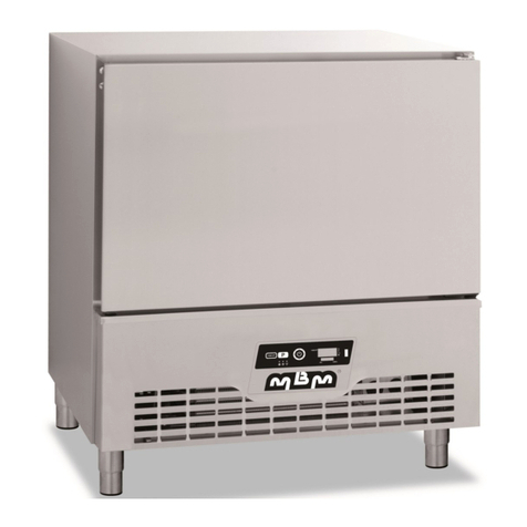
MBM A5A20 User manual

BLAST CHILLERS AND FREEZERS INSTALLATION MANUAL n° 6CE648070NI–0712
FORM049C1/3
INSTALLATION MANUAL
BLAST CHILLERS AND FREEZERS
Models: 5 Levels 12/6 and 20/10 kg
10 Levels 35/15 and 45/20 kg
13 Levels 60/25 and 80/40 kg

IMPORTANT RECOMMENDATIONS
The installation of this equipment should be entrusted to technicians
approved by the vendor and in compliance with standards and rules in force.
Before installing the unit ensure that the circulation and volume of air are
sufficient to allow normal cooling of the condenser and compressor.
Avoid installing the cabinet near major sources of heat or in direct sunlight.
Note that too high an ambient operating temperature can reduce
performance.
When connecting electrically “earth” continuity must be maintained between
the unit and the supply socket.
For cabinets supplied with a supply cable note that this is a specific part and
should only be replaced with an original part. Being considered as a circuit-
breaker, ensure that the plug is easily accessible as a means of electrical
isolation.
Protection against electrical overload or faults is the responsibility of the
installer. Ensure that a circuit breaker or fuses are fitted in the supply circuit
(See Name plate).
All operations on the electrical or refrigeration circuits, including cleaning
operations should only be undertaken with the unit DISCONNECTED
(unplugged socket).
The air-cooled compressor condenser must be cleaned regularly (every 3 to
6 months).
The unit should not be sprayed or splashed with water:
- Do not use a jet wash on the exterior or technical parts of the unit.
- The equipment must not be installed in the open air or exposed to the
elements.
During any intervention it is imperative that the factory systems are respected
so as not to compromise safety.
The correct operation of this equipment depends on the safety and operating
systems functioning as designed in the factory. We cannot be held responsible
for poor operation that results from inappropriate modifications.
The manufacturer can not be held responsible for usage other than that for
which the equipment was designed.
ALL SPECIFICATIONS AND CHARACTERISTICS IN THIS MANUAL MAY
BE SUBJECT TO CHANGE WITHOUT NOTICE

BLAST CHILLERS AND FREEZERS INSTALLATION MANUAL n° 6CE648070NI–0712
Page 1
TABLE OF CONTENTS
BLAST CHILLERS AND FREEZERS
Models: 5 Levels 12/6 and 20/10 kg
10 Levels 35/15 and 45/20 kg
13 Levels 60/25 and 80/40 kg
1. Technical Characteristics 2
1.1 5-level 12/6 and 20/10 2
1.2 10-level 35/15 and 45/20 3
1.3 13-level 60/25 and 80/40 4
2. Name plate 5
3. Installation 5
3.1 General requirements 5
3.2 Handling 5
3.3 Unpacking and installation 5
3.4 Connections 6
3.5 Assembly of HACCP sockets kits and rear Unit Grid 7
4. Commissioning 8
4.1 General requirements 8
4.2 Configuration of electronic regulation 8
4.3 Configuration of thermostat for fragile products 8
5. Electric diagrams 9
5.1 12/6, 20/10, 35/15 and 45/20 Units 9
5.2 60/25 Unit 10
5.3 80/40 Unit 11

BLAST CHILLERS AND FREEZERS INSTALLATION MANUAL n° 6CE648070NI–0712
Page 2
1. TECHNICAL CHARACTERISTIC
1.1 5-level 12/6 and 20/10
Dimensions (mm)
Height
Width
Depth
Outer
860
755
700
Inner
405
635
407
Weight (Kg)
12/6
20/10
Gross
120
130
Electric characteristics
Voltage
1~230V
Frequency
50 Hz
Protection
AM 4
Maximum power
600 W
900 W
Refrigeration characteristics
Refrigerant capacity (W)
510 à
–15/+32°C
920 à
–15/+32°C
Compressor
Hermetic
Evaporator
Air-Ventilated
Refrigerant
R404A
Condenser
Air
Acoustic pressure at 1
meter (dbA)
31
42
Heat emission
(W/cycle)
1514
3052
Capacities
Chill capacity by cycle
12 kg
20 kg
Freeze capacity by cycle
6 kg
10 kg
Gross capacity (L)
105
Wire shelves
GN1/1 (not included)
Max. level number
5
Temperatures
Max. ambient
+43°C
Temperature range
+63°C à +3°C - 90min
+63°C à –18°C - 240min
Construction
Type
Mono-shell
Inner/outer housing
304 Stainless Steel
Insulation
60 mm th. polyurethane
Standard
Safety : EN 60 335-1
Eur. : AC D 40 003
*Collective catering equipment
Refrigeration equipment (quick refrigeration and freezing Unit).
General rules for design and construction for ensuring hygiene
on utilization.
(1) Evacuation of water from defrost 20
(2)
Electric supply cable

BLAST CHILLERS AND FREEZERS INSTALLATION MANUAL n° 6CE648070NI–0712
Page 3
1.210-level 35/15 and 45/20
Dimensions (mm)
Height
Width
Depth
Outer
1550
755
700
Inner
800
635
407
Weight (Kg)
35/15
45/20
Gross
170
180
Electric characteristics
Voltage
1~230V
Frequency
50 Hz
Protection
AM 8
Maximum power
1600 W
1800 W
Refrigeration characteristics
Refrigerant capacity (W)
2080 à
–15/+32°C
2675 à
–15/+32°C
Compressor
Hermetic
Evaporator
Fan treated with
anticorrosion coating
Refrigerant
R404A
Condenser
Air
Acoustic pressure at 1
meter (dbA)
51
51
Heat emission
(W/cycle)
5120
5120
Capacities
Chill capacity by cycle
35 kg
45 kg
Freeze capacity by cycle
15 kg
20 kg
Gross capacity (L)
210
Wire shelves
GN1/1 (not included)
Max. level number
10
Temperatures
Max. ambient
+43°C
Temperature range
+63°C à +3°C - 90min
+63°C à –18°C - 240min
Construction
Type
Mono-shell
Inner/outer housing
304 Stainless Steel
Insulation
60 mm th. polyurethane
Standard
Safety : EN 60 335-1
Eur. : AC D 40 003
*Collective catering equipment
Refrigeration equipment (quick refrigeration and freezing Unit).
General rules for design and construction for ensuring hygiene
on utilization.
(1) Evacuation of water from defrost 20
(2) Electric supply cable

BLAST CHILLERS AND FREEZERS INSTALLATION MANUAL n° 6CE648070NI–0712
Page 4
1.313-level 60/25 and 80/40
Dimensions (mm)
Height
Largeur
Profond
Outer
1825
755
700
Inner
1075
635
407
Weight (Kg)
60/25
80/40
Gross
210
220
Electric characteristics
Voltage
1~230V
400V 3N~
Frequency
50 Hz
Protection
AM 10
Maximum power
2500 W
2500 W
Refrigeration characteristics
Refrigerant capacity (W)
4010 à
–15/+32°C
8020 à
–15/+32°C
Compressor
Hermetic
Evaporator
Air-Ventilated
Refrigerant
R404A
Condenser
à Air
Acoustic pressure at 1
meter (dbA)
60
66
Heat emission
(W/cycle)
10250
19426
Capacities
Chill capacity by cycle
60 kg
80 kg
Freeze capacity by cycle
25 kg
40 kg
Gross capacity (L)
280
Wire shelves
GN1/1 (not included)
Max. level number
13
Temperatures
Max. ambient
+43°C
Temperature range
+63°C à +3°C - 90min
+63°C à –18°C - 240min
Construction
Type
Mono-shell
Inner/outer housing
304 Stainless Steel
Insulation
60 mm th. polyurethane
Standard
Safety : EN 60 335-1
Eur. : AC D 40 003
*Collective catering equipment
Refrigeration equipment (quick refrigeration and freezing Unit).
General rules for design and construction for ensuring hygiene
on utilization.
(1) Evacuation of water from defrost 20
(2) Electric supply cable

BLAST CHILLERS AND FREEZERS INSTALLATION MANUAL n° 6CE648070NI–0712
Page 5
The sketch shows the "12/6 model" assembly
2. NAMEPLATE
The nameplate is to be found fixed on the bottom right of the cabinet.
For all correspondence relating to your equipment remember:
- The unit code (Type)
- The serial number (N° SERIE)
- The date (Date)
The main characteristics are repeated on a label fixed to the left hand internal panel.
3. INSTALLATION
3.1 GENERAL REQUIREMENTS
The installation, any repairs or alterations to this equipment should be undertaken by
qualified specialists according to good practice.
3.2 HANDLING
Handling must be carried out with adapted lifting devices.
If you have to carry the appliance, use the pallet of origin and in no case can it be
stacked on other appliances.
When transferring the appliance and in the absence of its pallet, the appliance must be
carried and not pulled.
3.3 UNPACKING AND INSTALLATION
3.3.1 UNPACKING
After having cut strapping (only for 10- and 13-level assemblies), remove the plastic film
with cardboard corners and the polystyrene protective bands.
View of packed equipment
Water drip tray
Adjustable
screw jack
Wooden pallet

BLAST CHILLERS AND FREEZERS INSTALLATION MANUAL n° 6CE648070NI–0712
Page 6
Lift the appliance to pull out its wooden pallet and install the assembly.
Level the equipment with the screw jacks. Note that door alignment may be adjusted by
adjusting the screw jacks of the front legs.
Install the drip tray.
3.3.2 INSTALLATION
When choosing a place for installation, make sure that air circulates sufficiently around
the appliance to allow for proper cooling of the condenser and compressor.
Leave a space of about 5 to 10cm between the walls and the unit.
Avoid the vicinity of a source of heat.
3.4 CONNECTIONS (See § 1 "Technical characteristics")
3.4.1 REFRIGERATING
Supplied fully pre-equipped with connected refrigerating unit and ready to operate, the
appliance does not need any particular refrigerating connection.
As a semi-equipped variant without compressor unit, the appliance is delivered with a
thermostatic regulator (positioned inside the evaporator housing), the suction tubes and liquid
line out in the technical housing.
3.4.2 ELECTRICS
The appliance is supplied with a supply plug that must in no case be removed.
Continuity of the earth circuit is imperative (see § important recommendations).
A circuit-breaker or protective fuses is to be installed by the installer.
As a semi-equipped variant without a compressor unit, the external compressor unit can
be supplied directly from the compressor unit contactor located on the electric plate of the
appliance.
For the semi-equipped appliance 12/6 without compressor unit, it is necessary to
include an external contactor with a coil supplied from the terminals 4 and 22 of the
appliance.
3.4.3 WATER FROM DEFROST
The appliance is supplied with a drip tray for recuperation water that must be emptied
regularly.
This drip tray can be replaced by a direct evacuation to waste (with a siphon to be
designed by the installer).

BLAST CHILLERS AND FREEZERS INSTALLATION MANUAL n° 6CE648070NI–0712
Page 7
3.5 KIT ASSEMBLY
3.5.1 HACCP SOCKET KIT
1°) Replace the 1-pin probe mounted as standard by
the 2-pin probe supplied with the kit by
connecting:
. both white cables instead the white and
red cables of the 1-pin standard probe
(terminals 31 & 32 of the DIN terminal strip
on the electric plate).
. the red cables 2 to both conductors that
remain free.
2°) Secure the connector base on the rear grid of the appliance
3°) Connect the cable of the connector base to the terminal strip on the electric plate.
In order to remove the grid of the control panel, unscrew both lower screws and pull the
grid in the direction of the arrows 1 and 2. Remove the hood for access to the plate. Pull the
plate according to the arrow 3
Rear grid
connector support
Connector base
Connector plug
Aperture for probe connecting cable
The sketch shows the "12/6 model" assembly
DIN terminal strip
Electric plate
(fixation by "Velcro grip" system)
Control panel
2
Lower screws
1
3
The sketch shows the "12/6 model" assembly

BLAST CHILLERS AND FREEZERS INSTALLATION MANUAL n° 6CE648070NI–0712
Page 8
4. COMMISSIONING
4.1 GENERAL REQUIREMENTS
Check that no foreign body obstructs the evaporator and condenser ventilators. If the
appliance was laid flat during transportation, wait 24 hours before putting it in service so as to
allow oil to return from the refrigerating circuit to the compressor pan (housing).
Install the grid runners on the racks.
4.2 PRESENTATION OF CONTROL PANEL KEY BOARD
Key 1: "HACCP" and key (-) Led 1°: Cycle "Soft Chill"
Key 2: "Select cycle" and key (+) Led 2°: Cycle "Defrost"
Key 3: "Start cycle" Led 3°: Cycle "Freezing"
4.3 CONFIGURATION OF ELECTRONIC CARD
4.3.1 PARAMETER CONFIGURATION
The assembly is factory-delivered with standard configuration, designed to meet most
current utilizations (see § 1.2, page 3 of the user’s manual). As necessary, this configuration
can be changed.
The modifications of the parameters are definitively taken into account even after the
assembly is switched off.
4.3.2 PARAMETER CONFIGURATION
When the appliance is switched on, press keys 1 and 2 simultaneously for 5 seconds to
access parameter programming. Parameter P01 is displayed.
To move from one number to another, depress key 2 or 1.
To display a pre-adjusted parameter in a number, depress key 3 and actuate keys 2 or 1
simultaneously to modify it. Release key 3 to move automatically to the following parameter.
Programming is left automatic when neither key is actuated for 5 seconds.
Key 1
Led 3
Led 1
Led 2
Key 2
Key 3

BLAST CHILLERS AND FREEZERS INSTALLATION MANUAL n° 6CE648070NI–0712
Page 9
4.3.3 PARAMETRES
Display
Condition
Description
Min
Max
Factory
adjust
Dim.
Notes
P01
Temperature scale
1
2
1
1=°C, 2=°F
P02
Ambient probe calibration
-10
10
0
°K
P03
Skewer probe activation
0
1
1
0=NO, 1=YES
P04
T2=1
Skewer probe calibration
-10
10
0
°K
P05
Action digital entry 1
0
1
0
0=NON, 1=DOOR
P06
DI1 = 1
Polarity Digital Entry 1
0
1
0
0=NO, 1=NF
P07
Action Digital Entry 2
0
2
0
0=NON, 1=DIGINP, 2=EVP
P08
DI2 = 1
Polarity Digital Entry 2
0
1
0
0=NO, 1=NF
P09
Display Digital Entry 2
0
1
0
0=CD, 1=HP
P10
DI2 = 2
Evaporator probe calibration
-10
10
0
°K
P11
Presence of bar graph
0
1
1
0 : No, 1: Yes
P12
Presence of light key
0
2
1
0 : No, 1: light key, 2:progression
cycle
P13
Type of buzzing sound
0
2
0
0: Frequency1(0.5s ON,0.5sOFF)
1: Frequency2(0.35sON,0.35sOFF)
2: Frequency3(0.25sON,0.25sOFF)
P14
Max duration of sound alarm
-1
99
1
min
-1 = buzzer never stops
P15
Alarm repeated afterwards
-1
99
5
min
-1 = norepeat
P16
Function Standby
0
1
1
0=NO, 1=YES
P17
Standby timer
1
60
10
min
P18
Anti-smell function
0
1
0
0=NO, 1=YES
P19
Anti-smell timer
1
120
60
min
interval between the start of two
functions
P20
Anti-smell duration
1
120
30
min
duration of function
P69
Max duration anti-smell function
-1
24
6
hrs
-1=lafonction dure sanslimite
P21
Display slowdown
0
100
0
P22
Machine number
1
255
1
P23
Manual defrost activated
0
1
1
0=NO, 1=YES
P24
Interval between 2 defrosting operations
0
99
6
hrs
P25
DI2=2
Temperature at end of defrost
-50
100
10
°C
Evaporator probe
P26
Max. duration of defrost
1
99
30
min
P27
Type of defrost
0
2
0
0=OFF, 1=ELE, 2=GAS
P28
Drainage time
0
99
3
min
P29
Check display on defrosting
0
60
10
min
P30
Ventilators activated during defrost
0
1
1
0=NO, 1=YES
P31
DI2=2
Temper. at ventilator switching on after
defrosting
-50
100
-5
°C
Evporator probe
P32
Ventilators switched off after defrost
0
60
0
min
P33
Defrost at the beginning of cooling cycle
0
1
0
0=NO, 1=YES
P34
Defrost at the beginning of conservation
cycle
0
1
0
0=NO, 1=YES
P35
Defrost delayed at the beginning of
conservation cycle
0
99
10
min
P36
Compressor delayed after switching on
0
30
0
min
P37
Min. time between 2 start-ups of
compressor
0
30
1
min
P38
Minimum standby duration after
compressor is switched off
0
30
1
min
P39
Compressor on with failing probe T1
0
30
3
min
P40
Compressor stopped with failing probe T1
0
30
6
min
P41
Compressor stop delayed by door opening
0
30
1
min
P42
Choice of cycle by default
0
3
0
0 = refriger. + S.P.,1 = delayed
refrigeration
2 = freezing +S.P., 3 = delayed
freezing

BLAST CHILLERS AND FREEZERS INSTALLATION MANUAL n° 6CE648070NI–0712
Page 10
P43
Setpoint refrigeration conservation
-50
100
3
°C
setpoint ofambient probefor
conservation
P44
Selection of soft chill cycle function
activated
0
1
1
0=NO, 1=YES
P45
SCE=1
Setpoint Soft chill ambient probe
-50
100
-5
°C
setpoint of ambient probe during
refrigeration cycle
P46
Selection of freezing cycle activated
0
1
1
0=NO, 1=YES
P47
Setpoint freezing conservation
-50
100
-21
°C
setpoint of ambient probe for
conservation
P48
Regulation differential
1
15
3
°K
P49
Duration of skewer probe presence test
0
99
60
s
P50
Check skewer probe inserted
0
99
5
°K
P51
Duration of pressure on key to switch off
cycle in progress
0
20
10
s
P52
Regulation type
0
2
1
0=FRA, 1=UK, 2=specified by user
P53
REG=2
High refrigeration limit
-50
100
63
°C
63°C for FRA, 70°C for UK
P54
REG=2
Setpoint of refrigeration cycle
-50
100
03
°C
10°C for FRA, 03°C for UK
P55
REG=2
Max. duration of refrigeration
1
180
90
min
120min for FRA, 90 min for UK
P56
REG=2
High freezing limit
-50
100
63
°C
63°C for FRA, 70°C for UK
P57
REG=2
Setpoint freezing cycle
-50
100
-18
°C
-18°C for FRA, -18°C forUK
P58
REG=2
Max. duration of freezing
1
400
240
min
300 min for FRA, 270min for UK
P59
REG=2
Temperature alarm mode
0
2
0
0=NO, 1=ABS, 2=REL
P60
ATM = 1
Low temperature absolute alarm
-50
100
-50
°C
P61
ATM = 2
High alarm absolute temperature
-50
100
99
°C
P62
ATM = 2
Low alarm differential
-12
0
0
°K
P63
ATM = 3
High alarm differential
0
12
0
°K
P64
ATM = 0
Temperature alarm delayed
0
120
60
min
P65
Door alarm delayed
0
30
5
min
P66
D2M=
1
Operation with condenser alarm
0
2
0
0=NO, 1=ALR, 2=STP
P67
T2
ALR
Display with sounding skewer probe.
0
1
0
0=E2, 1=UN
P68
Reset (default setting)
0
1
0
1=récupérerparamètrededéfaut
4.3.4 ALARMS AND FAULTS
The display indicates the type of error.
SAFETY AND UTILISATION
cE = Indicates a communication problem between the display card and the power box.
dEF = Indicates a defrost cycle in progress;
rEG = Indicate that the cycle has not progressed according to regulation.
One of key depressed deletes the message.
FAULTY FUNCTIONING
E1 = Faulty skewer probe –In case of a faulty skewer probe, it is always possible to use
the appliance in timer mode.
E2 = Faulty ambient probe.
The sound alarm can be switched off by depressing any key.
As regards a cycle in progress restarted after a sudden stop in one of the following cases:
. Current switched off during a refrigeration or freezing cycle:
Power cut duration unknown when the supply returns, the regulator switches to the
conservation mode and displays rEG
. Current switched off during a conservation cycle:
At end of power cut, the regulator carries on its conservation cycle

BLAST CHILLERS AND FREEZERS INSTALLATION MANUAL n° 6CE648070NI–0712
Page 11
5. ELECTRIC DIAGRAMS
5.1 MODELS 12/6, 20/10, 35/15 and 45/20
SdA : Ambient probe
SdP : Skewer probe
Cp : Compressor
Vc : Condenser Ventilator
Ve : Evaporator ventilator
Cd: Evaporator ventilator condenser
Rev : Re-evaporation resistance (option)
Vo : Anti-smell ventilator (option)
Details about electric diagram:
. without Cd1 for model 12/6
. without Ve2 for models 12/6, 20/10 and 35/15
Black
Brown
Blue
Black
Brown
Blue

BLAST CHILLERS AND FREEZERS INSTALLATION MANUAL n° 6CE648070NI–0712
Page 12
5.2MODEL 60/25
SdA : Ambient probe
SdP : Skewer prober
Cp : Compressor
Vc : Condenser ventilator
Ve : Evaporator ventilator
Cd: Evaporator ventilator condenser
HP : Pressure gauge
Rc : Pan (housing) resistance
KMG : Compressor unit contactor
Rev : Re-evaporation resistance
(option)
Vo : Anti-smell ventilator (option)
Black
Brown
Blue
Black
Brown
Blue

BLAST CHILLERS AND FREEZERS INSTALLATION MANUAL n° 6CE648070NI–0712
Page 13
5.3 MODEL 80/40
SdA : Ambient probe
SdP : Skewer prober
Cp : Compressor
Vc : Condenser ventilator
Ve : Evaporator ventilator
Cd: Evaporator ventilator condenser
HP : Pressure gauge
Rc : Pan (housing) resistance
KMG : Compressor unit contactor
f1 : thermicalrelay
Rev : Re-evaporation resistance (Biocell Plus)
Vo : Anti-smell ventilator (Biocell Plus)
Black
Brown
Blue
Black
Brown
Blue
Black
Brown
Blue
This manual suits for next models
1
Table of contents
Other MBM Chiller manuals