MRC FH-10A User manual

MRC Ltd
Fume Hood
FH (A) series
USER MANUAL
MRC Ltd
Thank you very much for purchasing our FH (A) series Fume Hood.
Please read the “Operating Instructions” and “Warranty” before
operating this unit to assure proper operation. After reading these
documents, be sure to store them securely together with the “Warranty”
within touch for future reference.
Warning: Before operating the unit, be sure to read carefully and
fully understand important warnings in the operating instructions.

MRC Ltd
2 http://www.mrclab.com/
CONTENT
1. Unpacking, Installation and Debugging .............................................................................................
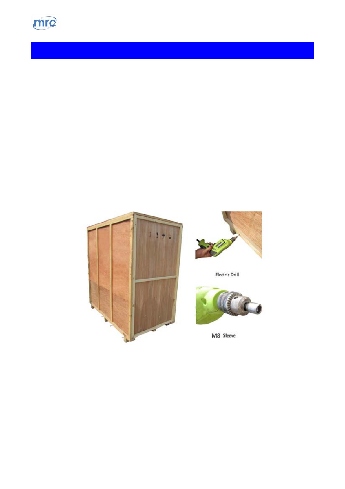
1.1 Unpacking of Main Body ..................................................................................................................
1.2 Unpacking of Base Cabinet .............................................................................................................6
1.3 Accessories Checking .......................................................................................................................
1.4 Installation Conditions and Operating Environment ........................................................................
1.5 Installation........................................................................................................................................9
1.6 Inspection after Installation................................................................................................................
2. User Instructions ..................................................................................................................................
2.1 Functions............................................................................................................................................
2.2 Product Structure ...........................................................................................................................16
2.3 Control Panel .....................................................................................................................................
2.4 Instructions of Operation ...................................................................................................................
2.5 Regular Maintenance .........................................................................................................................
2.6 Replacement Parts List..................................................................................................................26
2.7 Wiring Diagram.............................................................................................................................28
3. Trouble Shooting and Labels...........................................................................................................29
3.1 Common Failures and Solutions....................................................................................................29
3.2 Label Description...............................................................................................................................
4. Warranty ..........................................................................................................................................34

MRC Ltd
3 http://www.mrclab.com/
1. Unpacking, Installation and Debugging
Please firstly check whether the packing box is in good condition. If the packing box is damaged,
please take photos and contact the freight carrier. MRC and its dealers are not responsible for
shipping damages
1.1.Unpacking of Main Body
Choose a proper unpacking method according to the actual situation.
1.1.1. For wooden box
a) Method 1 Necessary tools for unpacking: Electric drill with hexagon dead M8
Picture1

MRC Ltd
4 http://www.mrclab.com/
b) Method 2 Use M8 wrench to unpack
Picture2
The following diagram demonstrates quick unpacking procedures (Picture 3).
Remove the screws shown in the diagram below, then move the wooden pieces
to right and left.

MRC Ltd
5 http://www.mrclab.com/
Picture3
1.1.2. For cartoon box
Use scissor to cut the packing tape, take off the package cover, then move up the box
body.
Picture4

MRC Ltd
6 http://www.mrclab.com/
1.2.Unpacking of Base Cabinet
Choose a proper unpacking method according to the actual situation.
1.2.1. For wooden box
Please refer to the main body unpacking method (of wooden box) in the previous pages,
use M8 electric drill or M8 wrench to remove the screws and unpack the box.
Picture5
1.2.2. For cartoon box
Please refer to the main body unpacking method (of carton box) in the previous pages,
use scissor to cut the packing tape, take off the package cover and move up the box
body.
Picture6

MRC Ltd
7 http://www.mrclab.com/
1.3.Accessories Checking
Accessories are placed inside the working area and base cabinet. Please refer to 1.5.6. to take
out all accessories and check the completeness referring to this packing list.
Packing list (FH (A) Fume Hood)
Main body box:
No. Items Quantity
1 Main body 1 unit
2 User manual 1 pc
3 Certification of quality 1 pc
4 Inspection report 1 pc
5 UV lamp 1 pc
6 Fuse (5A) 1 pc
7 Fuse(10A) 1pc
8
Stainless steel hexagon socket head cap screw M10×20
Stainless steel hexagon nut M10
Stainless steel flat washer 10 and spring washer 10
4 sets
9 PP water sink with accessories 1 set
10 Power cord 1 pc
11 Motorcontrolrod 1pc
12 Allen wrench 1 pc
Base cabinet box:
No. Items Quantity
1 Base stand 1 unit
2 Exhaust duct 1 pc
3 Duct clamp 1 pc

MRC Ltd
8 http://www.mrclab.com/
1.4.Installation Conditions and Operating Environment
1.4.1. Location requirements
To avoid disturbances to the Fume Hood and its operator, please follow the guideline
below, while determining a suitable location for the equipment
a) Fume Hood should not be installed in positions where they are likely to be
affected by other items or equipment. Windows, doorways, fans, room air supply
diffuser or ventilation outlet should be away from the Fume Hood.
b) The distance from the front window to any circulation space or air-handling
equipment should be at least 1000 mm, so as to preserve a zone undisturbed by
anyone other than the operator
c) The position of a Fume Hood should satisfy the spatial requirements (e.g. vision,
lighting and convenience of access) of the operator and personnel working
nearby.
d) When a Fume Hood is installed on a bench top, the leading edge should be flush
with or slightly overhanging the edge of the bench top.
1.4.2. Environment requirements
a) Only applicable to indoor operation
b) Ambient temperature: 15℃~35℃
c) Relative humidity: ≤75%
d) Atmospheric pressure range: 70 kPa~106 kPa
1.4.3. Electrical requirements
a) Electrical parameters: consistent with the rated voltage of the Fume Hood (See
2.1.4 Technical parameters and 2.1.5 Performance index)

MRC Ltd
9 http://www.mrclab.com/
b) Power supply need to be grounded (Judging method: test the live wire and the
neutral wire of the main socket with multimeter. The voltage between live and
ground should equal to the voltage of local electrical grid, and the voltage
between neutral and ground should equal to 0. Otherwise, the power supply is
not grounded correctly.)
c) Test the voltage stability before using. If the voltage is unstable, use a voltage
regulator to adjust. Otherwise, the control panel and transformer may be easily
damaged
1.5.Installation
1.5.1. Remove all the package materials
1.5.2. Check the surface of the base cabinet and the main body to make sure there is no
scratch, deformation or foreign bodies
1.5.3. Move the whole equipment as close as possible to the final installation place
NOTE: Do NOT turnover, disassemble or slant the cabinet during
transportation.
1.5.4. Position the base cabinet to the final location where an appropriate power supply is
nearby; and brake the caster to stabilize the base cabinet
1.5.5. Make sure the voltage and frequency of power supply is same as the required value
which is shown on the label. Take out the power cord from the packaging box and
connect it with the female power cord connector on the main body. Plug in the other end
to connect a power supply
1.5.6. Press the “ ” button on the control panel to power on the equipment. Afterwards,
press the “ ” button to raise the front window, take out the accessories from the
operating area and remove the work table as shown in the picture below. Lastly, power
off the equipment and prepare for installation.

MRC Ltd
10 http://www.mrclab.com/
Picture 7
1.5.7. Connect base cabinet with main body
a) Lift the main body and place it on the base cabinet. Make sure each side is in
alignment. Besides, please also make sure the mounting holes of bolt (as shown
in Picture 9) at the bottom of the main body are in alignment with the holes on
the top plate of the base cabinet
b) Make sure the main body and base cabinet are stable enough to prevent side-slip.
Open the doors of the base cabinet and take out the components from the
accessory bag
Stainless steel hexagon socket head cap screw M10×20
Stainless steel hexagon nut M10
Stainless steel flat washer 10 and spring washer 10
Insert the hexagon socket head cap screws (M10×20) into the holes at the bottom
of the main body (refer to the Picture 8). These screws should pass through the
main body and the base cabinet. Use flat washer 10, spring washer 10 and nut
Pull out this work
table to reveal the
bolt holes

MRC Ltd
11 http://www.mrclab.com/
M10 to fasten the screws and nuts. Make sure the base cabinet is well connected
with the main body.
Picture 8
1.5.8. Installation of water tap and gas tap
Insert the work table and mount the water sink on the reserved sink hole.
Connect the laboratory water pipe and gas pipe (inflow) with the lower end of the taps.
Pass the drainpipe (provided) through the reserved hole at the side of the base cabinet
(refer to Picture 10) and connect it with the sewer pipe in the laboratory room (water
sink and drainpipe have been connected in factory)
Picture 9
Water sink
Water tap
Four screws to secure
the base cabinet to the
main body

MRC Ltd
12 http://www.mrclab.com/
Picture 10
1.5.9. Installation of exhaust duct
Take out the duct clamp and the exhaust duct. Put the clamp on the exhaust duct and
then connect the exhaust duct with the air exhaust outlet on top of the Fume Hood.
Afterwards, use Slotted screwdriver to fasten the duct clamp firmly. The other end of
the exhaust duct should be fixed outside the laboratory room and in the open air.
Picture 11
Gas inlet
Water inlet
Drain hose
Exhaust duct
Air exhaust outlet
Duct clamp Slotted screwdriver

MRC Ltd
13 http://www.mrclab.com/
1.6.Inspection after Installation
Refer to this table and follow the instruction in 2.4.2, check the following items after
powering on the Fume Hood.
Checking Items Normal working status
Power status
Equipment could be powered on/switched off when press the
power button
Fan
Runs normally after pressing the Fan button; speed could be
adjusted by pressing the adjusting button
Front window
Front window could be moved smoothly by pressing the UP
and DOWN buttons
Fluorescent lamp Lamp lights up after pressing button
UV Lamp Lamp lights up after pressing button
Socket
Use multimeter to test voltage output after pressing the
socket button
NOTE: Please contact MRC technical department or agent for inspection or
trouble shooting when problems could not be solved. Methodology of trouble
shooting is stated in the After-sale Service Manual.

MRC Ltd
14 http://www.mrclab.com/
2. UserInstructions
2.1.Functions
2.1.1. Product concept
This product belongs to FH (A) series Fume Hood. Fume Hood is a kind of negative
pressure ventilation system for protecting operator and laboratory environment. Room
air flows inward from the front opening of the Fume Hood and is consistently ventilated
by the extract blower. Therefore, contaminated fumes, vapors, toxic gasses, aerosol and
corrosive substance which are probably generated during experiments could be
prevented from spreading to the operator or into the laboratory room. In addition, the
polluted air could be purified by the active carbon filter (optional) before exhausting
through the duct. Thus, the outdoor environment could also be protected.
NOTE: Experiments with the use of flammable, explosive substances and
strong acids or bases should NOT be conducted by this FH (A) series Fume Hood.
2.1.2. Operating principle/air flow pattern
Picture12

MRC Ltd
15 http://www.mrclab.com/
2.1.3. Protected object
The primary goal of the Fume Hood is to protect operators and laboratory environment
from exposure to infectious aerosol and toxic fumes which may be generated from the
reaction during experiments.
2.1.4. Technical parameters
Model
Parameter
FH-10A FH-12A FH-15A FH-18A
Rated Voltage AC 220V±10% 110V±10%
Rated Frequency 50 Hz 60Hz
External Dimension
(W*D*H)
1040*800*2200 mm 1240*800*2200 mm 1540*800*2200 mm 1840*800*2200 mm
Working Zone
Dimension (W*D*H)
820*670*730 mm 1020*670*730 mm 1320*670*730 mm 1620*670*730 mm
Power Supply
Consumption
400 W 400 W 500 W 500 W
Inflow Velocity 0.3~0.8m/s
Maximum Opening 500mm 500mm 500mm 500mm
UV Lamp Consumption 20W 20W 30W 30W
Fluorescent Lamp
Consumption
T5 8W T5 12W T5 16W T5 16W
Noise ≤70dB(A)
NOTE: a) Power supply consumption includes the consumption loaded at
working zone, which should not exceed 500W.
b) MRC reserves the right to make changes in future product design,
without reservation and without notification to its users.

MRC Ltd
16 http://www.mrclab.com/
2.1.5. Performance index
a) Vibration amplitude
The net vibration amplitude, at a range of frequency from 10 Hz to 10 KHz,
would not exceed 5 μm (rms)
b) Illumination
The average illumination would not less than 400 lux. Tested real illumination
would not less than 350 lux
c) Electrical performance
Dielectric Withstand Test: the Fume Hood would not breakdown in 5s when the
voltage increases by 1390V (AC) within 5s
Ground resistance ≤0.1Ω
2.2.Product Structure
2.2.1. Structural composition of FH(A) Series Fume Hood
Picture 13

MRC Ltd
1. Caster
2. Base cabinet
3. Water sink
4. Water tap
5. Water tap control knob
6. Gas tap control knob
7. Access panel
8. Control panel
9. Gas tap
10. Power socket
11. Fuse holder
12. Exhaust outlet
13. Front window
14. Phenolic compact laminate
15. Work table
16. Socket
17. Gas inlet
18. Water inlet
19. Drain hose
2.2.2. Structure introduction
a) Driving system of front window
Driving system consists of tubular motor, front window and hauling mechanism
(hauling sash)
b) UV lamp
The entire work zone could be sterilized effectively by the UV lamp located at
the top of work zone. Emission of 253.7 nanometers could ensure the most
efficient decontamination.
c) Fluorescent light
The Fume Hood is equipped with LED lamp tube, which ensures the standard
requirement of average illumination (400 lux) is met. The measured value at any
point inside the working zone should be greater than 350 lux.

MRC Ltd
18 http://www.mrclab.com/
d) Socket
Socket, located at the two sides beside the front opening, could supply electricity
power for devices used in experiments and could be controlled by the
button.
NOTE: Please make sure the total load of sockets should be ≤500W.
e) Fuse protector
Fuse holders are installed on the top right of the equipment (refer to Figure 13).
Fuse of live wire is inside the female power cord connector. Socket (working
zone) fuse holder and neutral wire (power source) fuse holder is beside the
female connector . The specification of each fuse tube complies with the label
right below the fuse holder. Please refer to the label when replace the fuse tube.
f) Structure
i. External case body adopted 1.0 mm cold-rolled steel in double layer
structure with electrostatic coating and rust-proof treatment. The
structural strength and stability are enhanced.
ii. Inner wall of work area is fully made of Phenolic Compact Laminate
which provides corrosion resistance as well as attractive appearance;
work table is made of solid chemical resistant laminate which is easy to
clean and wash.
iii. Fume hood front window adopted 5 mm toughened glass.
iv. Control panel adopted soft-touch buttons and microprocessor control
system that make the operation easily to be controlled
v. The electronic control system could prevent overload of the circuit and
electric shock, stabilize the performance, protect the equipment and
extend the use life of the Fume Hood.
vi. The sockets (at working zone) adopted non-flammable PC material that is
specialized for laboratory use

MRC Ltd
19 http://www.mrclab.com/
2.3.Control Panel
2.3.1. Soft touch buttons
Main functions could all be executed by pressing the relevant button. There are totally 8
common buttons on the control panel (refer to Picture 14). The indicator light above
each button shows the working status of the relevant function. The small LED display
shows the speed level of the blower.
Picture14
Power button, the main switch of the Fume Hood
Fluorescent lamp, press to turn on the light, interlocked with UV lamp
UV lamp, only works when both the blower and the fluorescent lamp are turned off
Front window up, press and hold to continuously raise the window
Blower (Fan), press to turn on the blower, interlocked with UV lamp

MRC Ltd
20 http://www.mrclab.com/
Front window down, press and hold to continuously lower the window
Socket power, press to activate the sockets in the working zone
Adjust fan speed, press to adjust the speed of the blower (fan) from F1 to F9
2.3.2. Control of the front window
The height of the front window could be adjusted by pressing the and
buttons. The window will be moved continuously when pressing the button and it will
stop moving immediately when the button is released
Please make sure the height of the front window is within the safety height range (520
mm).
2.3.3. Control of the fan speed
The blower (fan) could be turned on by pressing button (only when the UV lamp
is turned off). The speed of the fan could be adjusted by pressing button. 9 speed
levels could be selected. The relevant speed level would be displayed on the LED
screen.
When turn off the blower or power off the Fume Hood, the level of fan speed is
memorized by the equipment and would be resumed when turn on the blower again.
2.3.4. UV sterilization
UV light could be turned on by pressing the UV button. Please make sure the window is
fully closed before starting UV sterilization. Interlock function was adopted between
UV light and the blower/fluorescent light. UV light could be automatically turned off
when either the blower or fluorescent light is turned on. During sterilization, people
should leave the room for safety of eyes and skin.
2.4.Instructions of Operation
2.4.1. Normal Operation Notice
a) Make sure input voltage is correct and stable. The rated load of main power
socket should be higher than cabinet consumption. Plug must be well grounded.
This manual suits for next models
13
Table of contents
Popular Ventilation Hood manuals by other brands

System air
System air 382-16 operating instructions

Blue Star
Blue Star PRO LINE PL30240 Installation use and care manual

V-ZUG
V-ZUG DWVMR9 operating instructions

System air
System air 251-14 EC User instructions

FAL
FAL FAL-60-55RDS instruction manual

ROROS HETTA
ROROS HETTA Trend User and installation manual

Master cook
Master cook WK-Cristal Use and care guide

AEG
AEG 240 D Operating and installation instructions

GE
GE MONOGRAM ZV750SY Installation instructions manual

Zanussi
Zanussi ZHP60260WA installation manual

FALMEC
FALMEC K12115702007K Instruction booklet

Whirlpool
Whirlpool AKR 703 IX AKR 703 IX Instructions for use