ETAS ES1331.1 User manual

Artisan Technology Group is your source for quality
new and certied-used/pre-owned equipment
• FAST SHIPPING AND
DELIVERY
• TENS OF THOUSANDS OF
IN-STOCK ITEMS
• EQUIPMENT DEMOS
• HUNDREDS OF
MANUFACTURERS
SUPPORTED
• LEASING/MONTHLY
RENTALS
• ITAR CERTIFIED
SECURE ASSET SOLUTIONS
SERVICE CENTER REPAIRS
Experienced engineers and technicians on staff
at our full-service, in-house repair center
WE BUY USED EQUIPMENT
Sell your excess, underutilized, and idle used equipment
We also offer credit for buy-backs and trade-ins
www.artisantg.com/WeBuyEquipment
REMOTE INSPECTION
Remotely inspect equipment before purchasing with
our interactive website at www.instraview.com
LOOKING FOR MORE INFORMATION?
Visit us on the web at www.artisantg.com for more
information on price quotations, drivers, technical
specications, manuals, and documentation
Contact us: (888) 88-SOURCE | sales@artisantg.com | www.artisantg.com
SM
View
Instra

ES1331.1
Signal Generator Board (4-CH)
User’s Guide
Artisan Technology Group - Quality Instrumentation ... Guaranteed | (888) 88-SOURCE | www.artisantg.com

ES1331.1 Signal Generator Board (4-CH)2
Copyright
The data in this document may not be altered or amended without special
notification from ETAS GmbH. ETAS GmbH undertakes no further obligation in
relation to this document. The software described in it can only be used if the
customer is in possession of a general license agreement or single license.
Using and copying is only allowed in concurrence with the specifications stip-
ulated in the contract.
Under no circumstances may any part of this document be copied, repro-
duced, transmitted, stored in a retrieval system or translated into another lan-
guage without the express written permission of ETAS GmbH.
© Copyright 2000 - 2003 ETAS GmbH, Stuttgart, Germany
The names and designations used in this document are trademarks or brands
belonging to the respective owners.
R1.0.2 EN - 07.2003 TTN F 00K 700 304
Artisan Technology Group - Quality Instrumentation ... Guaranteed | (888) 88-SOURCE | www.artisantg.com

Contents 3
Contents
1Introduction . . . . . . . . . . . . . . . . . . . . . . . . . . . . . . . . . . . . . . . . . . . . . . . . . . . . . 5
1.1 Features . . . . . . . . . . . . . . . . . . . . . . . . . . . . . . . . . . . . . . . . . . . . . . . . . . 5
1.2 Applications . . . . . . . . . . . . . . . . . . . . . . . . . . . . . . . . . . . . . . . . . . . . . . . 6
1.3 Block Diagram . . . . . . . . . . . . . . . . . . . . . . . . . . . . . . . . . . . . . . . . . . . . . . 7
2Hardware . . . . . . . . . . . . . . . . . . . . . . . . . . . . . . . . . . . . . . . . . . . . . . . . . . . . . . . 9
2.1 Functional Description . . . . . . . . . . . . . . . . . . . . . . . . . . . . . . . . . . . . . . . . 9
2.1.1 Digital Signal Processor. . . . . . . . . . . . . . . . . . . . . . . . . . . . . . . . 9
2.1.2 Virtual Dual-Ported RAM . . . . . . . . . . . . . . . . . . . . . . . . . . . . . . 9
2.1.3 Digital/Analog Converters. . . . . . . . . . . . . . . . . . . . . . . . . . . . . . 9
2.1.4 Interface to the Piggyback Module . . . . . . . . . . . . . . . . . . . . . . 10
2.1.5 VMEbus Interface . . . . . . . . . . . . . . . . . . . . . . . . . . . . . . . . . . . 10
2.2 Hardware Configuration . . . . . . . . . . . . . . . . . . . . . . . . . . . . . . . . . . . . . 10
2.2.1 Base Address . . . . . . . . . . . . . . . . . . . . . . . . . . . . . . . . . . . . . . 12
2.2.2 Interrupt number . . . . . . . . . . . . . . . . . . . . . . . . . . . . . . . . . . . 13
2.2.3 Boot Program Source . . . . . . . . . . . . . . . . . . . . . . . . . . . . . . . . 13
2.2.4 Supply Voltage Output . . . . . . . . . . . . . . . . . . . . . . . . . . . . . . . 14
2.2.5 Supply Voltage for 12 V Stand-Alone Mode . . . . . . . . . . . . . . . 14
2.3 Pin Allocation . . . . . . . . . . . . . . . . . . . . . . . . . . . . . . . . . . . . . . . . . . . . . 15
2.3.1 Connector X1: Analog Outputs . . . . . . . . . . . . . . . . . . . . . . . . 15
Artisan Technology Group - Quality Instrumentation ... Guaranteed | (888) 88-SOURCE | www.artisantg.com

Contents4
2.3.2 Connector X2: Optional Digital Inputs and Outputs . . . . . . . . . 16
2.4 Technical Data . . . . . . . . . . . . . . . . . . . . . . . . . . . . . . . . . . . . . . . . . . . . . 17
3ETAS Contact Addresses . . . . . . . . . . . . . . . . . . . . . . . . . . . . . . . . . . . . . . . . . . . 21
List of Figures . . . . . . . . . . . . . . . . . . . . . . . . . . . . . . . . . . . . . . . . . . . . . . . . . . . 23
List of Tables. . . . . . . . . . . . . . . . . . . . . . . . . . . . . . . . . . . . . . . . . . . . . . . . . . . . 25
Index . . . . . . . . . . . . . . . . . . . . . . . . . . . . . . . . . . . . . . . . . . . . . . . . . . . . . . . . . 27
Artisan Technology Group - Quality Instrumentation ... Guaranteed | (888) 88-SOURCE | www.artisantg.com

Introduction 5
1Introduction
This section contains information about the basic features and applications of
the ES1331.1 Signal Generator Board. A block diagram shows the schematic
layout of the plug-in board.
1.1 Features
The ES1331.1 Signal Generator Board is used to generate analog and digital
output signals in VMEbus systems. The plug-in board has its own digital signal
processor (DSP) working independently from the main processor of the VME
system.
By using a DSP, the signal form of the output signal can be programmed as
desired; even stringent requirements regarding the variation speeds of ampli-
tude, frequency, and pulse width can be met with ease.
The 64Kword virtual dual-ported RAM (DPRAM) allows write/read access by
both the system processor and the DSP. This memory area is intended for the
exchange of programs and data between the DSP and the system processor.
Optionally, the DSP can use an additional 64-Kword EPROM as program mem-
ory. This memory area can be write-accessed by the DSP.
For analog signal generation, the plug-in board has four digital/analog con-
verters with 12-bit resolution and a maximum conversion delay of 6 msec. The
output voltage range is -10 V to +10 V relative to the ground potential of the
VMEbus system.
The digital output signals are generated by a piggyback module providing
eight counters. Every two counters form one output channel. The address,
data and control lines of the DSP are passed on to the piggyback module.
The board has the following features:
• TMS320C203 digital signal processor
• 64-Kword virtual dual-ported RAM as program or data memory
• four digital/analog converters with 12-bit resolution and a max. output
voltage range of –10 V to +10 V
• front panel ports for analog and digital output signals
note
Some components of the ES1331.1 may be damaged or destroyed by electro-
static discharges. Therefore, keep the plug-in board in its storage package until
it is installed.
The ES1331.1 may only be taken from the storage package, configured and
installed at a working place that is protected against static discharges.
Artisan Technology Group - Quality Instrumentation ... Guaranteed | (888) 88-SOURCE | www.artisantg.com

Introduction6
• interrupt generation on the VME bus
• VMEbus interface
• optional 64-Kword EPROM as program or data memory
• piggyback module for digital signal generation
The following figure shows the front panel and the position of the connectors.
Fig. 1-1 Front panel
1.2 Applications
The ES1331.1 Signal Generator Board is intended for use in VMEbus systems
where analog and digital signal shapes of different frequencies, amplitudes,
and pulse widths need to be generated. The digital signal processor (DSP)
allows flexible signal generation independently from the system processor.
ES1331.1
X1
X2
Artisan Technology Group - Quality Instrumentation ... Guaranteed | (888) 88-SOURCE | www.artisantg.com

Introduction 7
Sample applications are:
• generation of active or passive speed sensor signals for driving-dynamics
systems
• generation of speed signals for gearbox control units
1.3 Block Diagram
The following figure shows a block diagram of the ES1331.1 Signal Generator
Board
Fig. 1-2 Block diagram
In the center of the block diagram, you can see the digital signal processor. To
the right of the signal processor is the dual-ported RAM manager that allows
access to the 128-KB RAM by the DSP and VME bus. To the left of the DSP, you
can see the four digital/analog converters and the signal conditioner for the
four analog outputs.
The data, address, and control signals of the DSP, as well as the digital outputs
of the front panel, are passed on to a piggyback module.
The piggyback module contains eight counters in four groups that can be used
to generate PWM signals with variable frequencies and pulse duty factors.
Signal
Conditio-
ning
128 kB
RAM
Dual-
Ported
RAM
Manager
VME-
Inter-
face
Analog
Outputs
VME-
Bus
Digital
Outputs
Digital
Signal
Processor
4
D/A-
Converter
Piggy-
back
Artisan Technology Group - Quality Instrumentation ... Guaranteed | (888) 88-SOURCE | www.artisantg.com

Introduction8
Artisan Technology Group - Quality Instrumentation ... Guaranteed | (888) 88-SOURCE | www.artisantg.com

Hardware 9
2 Hardware
This section contains a detailed functional description, information about the
jumpers and solder straps, the pin allocation of the connectors, and the tech-
nical data of the ES1331.1 Signal Generator Board.
2.1 Functional Description
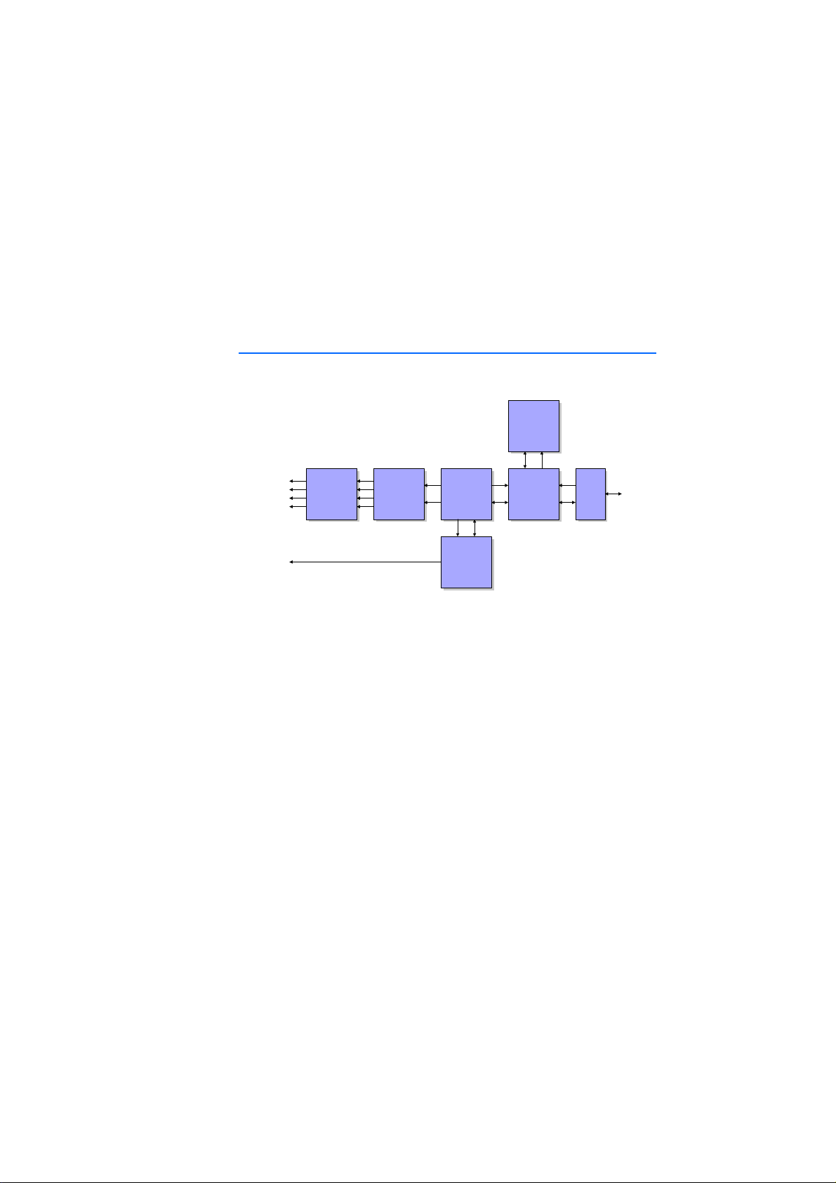
This section gives you a detailed overview of the features of the ES1331.1 Sig-
nal Generator Board. You will find information on the following subjects:
• digital signal processor
• virtual dual-ported RAM
• analog/digital converter
• interface to the piggyback module
• VMEbus interface
2.1.1 Digital Signal Processor
The digital signal processor TMS320C203 is used as the CPU of ES1331.1. The
digital signal processor (DSP) can operate independently from the main proces-
sor of the VME system. Data are exchanged between the two processors via a
virtual dual-ported RAM. The processing performance of the signal processor
is 40 MIPS with a word size of 16 bits. The signal processor has an internal
544-word program or data memory.
The signal processor can be started either from an external EPROM or from the
dual-ported RAM. This can be selected by jumpers.
2.1.2 Virtual Dual-Ported RAM
The virtual dual-ported RAM is used for the communication between the main
processor of the VME system and the digital signal processor. The two proces-
sors can access a shared RAM area of 128 KB (64 Kwords) via a dual-ported
RAM manager. The dual-ported RAM manager prevents address conflicts and
prioritizes the access requests.
The dual-ported RAM can be used both for data and program storage. The
program of the signal processor can be loaded from the VME system processor
into the dual-ported RAM; it can then be used to start the DSP.
2.1.3 Digital/Analog Converters
The four digital/analog converters of the ES1331.1 have a 12-bit resolution at
a maximum conversion delay of 6 µsec. The output voltage range is -10 V to
+10 V relative to the ground potential of the VME system. The output voltages
of all four D/A converters can be output in sync with each other.
Artisan Technology Group - Quality Instrumentation ... Guaranteed | (888) 88-SOURCE | www.artisantg.com

Hardware10
2.1.4 Interface to the Piggyback Module
An optional piggyback module can be used to implement additional memory
or peripheral functions. The address, data and control signals of the signal pro-
cessor, as well as the analog output signals, are passed to the piggyback mod-
ule. 13 lines run from the front panel connector to the piggyback module.
2.1.5 VMEbus Interface
For the VME bus, the ES1331.1 has a slave interface with 16 or 24 address lines
and 16 data lines. The base address of the board is set via hex switches. The
board occupies an address range of 128 KB.
The board can generate interrupts on the VME bus. The interrupt level is
selected via solder straps. The interrupt vector is set by software either from
the DSP or from the system processor.
2.2 Hardware Configuration
This section contains the information required for configuring the jumpers of
the ES1331.1 Signal Generator Board. The jumpers are used to configure the
following settings:
• VMEbus base address
• interrupt number
• boot program source
• supply voltage output
• supply voltage for 12 V stand-alone mode
Artisan Technology Group - Quality Instrumentation ... Guaranteed | (888) 88-SOURCE | www.artisantg.com

Hardware 11
The figures below show the position of the jumpers and solder straps on the
component and solder sides of the board.
Fig. 2-1 Jumpers and solder straps (component side)
J5
X1
X2
J6
HEXHN HEXLN
X5
X3
X4
ROMSEL
3 2 1
Artisan Technology Group - Quality Instrumentation ... Guaranteed | (888) 88-SOURCE | www.artisantg.com

Hardware12
Fig. 2-2 Solder straps (solder side)
2.2.1 Base Address
The base address of the ES1331.1 Signal Generator Board is selected by the
two hex switches HEXHN and HEXLN.
The board occupies an address range of 128 KB from the base address.
note
The solder straps Pa to Pd, LP8, and LP9 determine manufacturer options and
may not be modified.
note
Make sure that the address range of the ES1331.1 Signal Generator Board does
not overlap the address ranges of other boards in your system.
X1
X2
Pa
Lp8
Lp9
P1
P2
P3
P4
P5
P6
P7
Pb
Pc
Pd
P9P10 P8
Artisan Technology Group - Quality Instrumentation ... Guaranteed | (888) 88-SOURCE | www.artisantg.com

Hardware 13
2.2.2 Interrupt number
The solder straps P1 to P10 determine the interrupt number.
2.2.3 Boot Program Source
Use the jumper ROMSEL to select the source of the boot program for the signal
processor.
Switch Address Default setting
HEXHN A23 - A20 $C
HEXLN A19 - A18 $0
Tab . 2 -1 Setting the base address
Solder strap Interrupt number Default setting
P1 1 open
P2 2 open
P3 3 open
P4 4 open
P5 5 open
P6 6 open
P7 7 open
P8 8 open
P9 9 open
P10 10 open
Tab . 2 -2 Setting the interrupt number
note
Only one of the solder straps P1 to P10 may be closed.
note
"Boot from ROM" (pin 2 and 3 bridged) may only be set, if the ES1331.1 is
equipped with an appropriate piggyback module.
Without an appropriate piggyback module, there is no boot ROM available to the
signal processor.
Artisan Technology Group - Quality Instrumentation ... Guaranteed | (888) 88-SOURCE | www.artisantg.com

Hardware14
2.2.4 Supply Voltage Output
Use the jumper J5 to connect the +5 V supply voltage of the VME system with
pin 5 of the front panel connector X1.
2.2.5 Supply Voltage for 12 V Stand-Alone Mode
The ES1331.1 includes DC/DC converters allowing it to be used with the VME
bus, connected only to a 12 V supply voltage.
Pin Description
1-2 Boot from RAM
2-3 Boot from ROM (default)
Tab . 2 -3 Setting the source of the boot program
Jumper open closed
J5 X1 pin 5 empty X1 pin 5 set to +5 V supply
voltage (default setting)
Tab . 2 -4 Selection of the supply voltage output
note
The jumper J6 may not be inserted if the board is operated with the VME bus.
Jumper open closed
J6 Operation with VME bus
(default setting)
Operation with a single 12 V
supply
Tab . 2 -5 Selection of stand-alone mode
Artisan Technology Group - Quality Instrumentation ... Guaranteed | (888) 88-SOURCE | www.artisantg.com

Hardware 15
2.3 Pin Allocation
This section describes the pin allocations of the ES1331.1 Signal Generator
Board.
2.3.1 Connector X1: Analog Outputs
The connector X1 includes the four analog output signals of the ES1331.1.
The connector also provides a +5 V voltage supply for external assemblies.
Fig. 2-3 Connector X1: Analog Outputs
Pin Function Pin Function
1 Channel 1 2 Channel 2
3Channel 3 4Channel 4
5 +5 V output 6 Analog GND
7Analog GND 8Analog GND
9 Analog GND Analog GND
Tab . 2 -6 Input Allocation X1: Analog Outputs
note
The +5 V output voltage at pin 5 is only available when the jumper J5 is set.
1
6
4
7
8
2
3
95
Artisan Technology Group - Quality Instrumentation ... Guaranteed | (888) 88-SOURCE | www.artisantg.com

Hardware16
2.3.2 Connector X2: Optional Digital Inputs and Outputs
The connector X2 contains the 14 input and output lines of the piggyback
module. The pin layout of this connector depends on the functions of the pig-
gyback module.
Fig. 2-4 Connector X2: Optional Inputs/Outputs
Pin Function Pin Function
1 X3 Pin 1 2 X3 Pin 3
3X3 Pin 5 4X3 Pin 7
5 GND 6 X3 Pin 11 and -15 V DC
7X3 Pin 13 and +15 V DC 8 VCC (DC-DC converter)
9 X3 Pin 2 10 X3 Pin 4
11 X3 Pin 6 12 X3 Pin 8
13 X3 Pin 10 14 X3 Pin 12
15 X3 Pin 14
Tab . 2 -7 Pin Allocation X2: Optional Inputs/Outputs
14
1
9
4
10
11
2
3
12
13 5
6
15 7
8
Artisan Technology Group - Quality Instrumentation ... Guaranteed | (888) 88-SOURCE | www.artisantg.com

Hardware 17
2.4 Technical Data
This section contains the technical data of the ES1331.1 Signal Generator
Board in tabular form.
Digital Signal Processor
Analog Outputs
Digital Outputs
Type TMS320C203
Cycle time 25 nsec
Word length 16 bits
Program/data storage 544 words internally
Resolution 12 bits
Voltage range -10 V to +10 V
Max. conversion delay 6 µsec
Number of channels 4
Max. data rate 166 k samples/sec
Max. output current 10 mA
Transient time 14 µsec (0.1% at 10 V step)
Number of counters 4 11-bit counters
4 5-bit counters
Number of output channels 4
Signal level 5 V
Artisan Technology Group - Quality Instrumentation ... Guaranteed | (888) 88-SOURCE | www.artisantg.com

Hardware18
Dual-Ported RAM
Flash-EPROM
VMEbus
Power Supply
Size 64 Kwords
Access time 50 nsec
150 nsec with interrupts from VME bus
Size 64 Kwords
Access time 120 nsec
Programmability by DSP
Type Slave interface
Address and data lines 24 bits address and 16 bits data
Base address $000000 to $FE0000 selected by hex switches
Address range 128 KB
Address modifier Standard or short supervisor/user data
Interrupt Single Level, IRQ 1 to 10
IRQ level, interrupt vector, and source selected by
jumpers
Interrupt source DSP program
VME bus mode 5 V DC, ±5%, max. 700 mA
12 V DC, ±5%, max. 200 mA
Stand-alone mode 12 V DC, ±5%, max. 900 mA
Artisan Technology Group - Quality Instrumentation ... Guaranteed | (888) 88-SOURCE | www.artisantg.com

Hardware 19
Environmental Conditions
Connectors
Physical Dimensions
Ambient temperature during
operation
0 °C to +70 °C (standard)
Storage temperature -55 °C to +85 °C
Relative humidity 0 to 90%, no condensation
Backplane 96-pin DIN 41612 C
Front panel Analog: 9-pin Submin-D,
piggyback module: 15-pin Submin-D
Circuit board 100 x 160 mm²
Front panel Height: 3 U
Width: 4 HP (20.3 mm)
Artisan Technology Group - Quality Instrumentation ... Guaranteed | (888) 88-SOURCE | www.artisantg.com
Table of contents
Popular Inverter manuals by other brands

Kodak
Kodak OG-Plus3.24RM Installation & user manual

Universal Motors
Universal Motors UMA1 Series Operation manual

Victron energy
Victron energy Phoenix 12/220 user manual

Siemens
Siemens SINAMICS G120 Function manual

Wagan
Wagan Smart AC 150 USB user manual

YSmart Technology
YSmart Technology IP Series Grid Tie inverter user manual