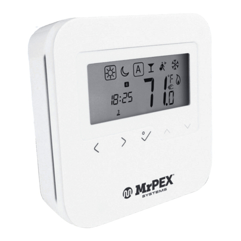
MrPEX 5110740 User manual

THERMOSTAT INSTALLATION
MRPEXSYSTEMS.COM94
THERMOSTAT INSTALLATION
INSTALLATION INSTRUCTIONS FOR
DIGITAL THERMOSTAT #5110740
PREPARATION: This is a Low Voltage Thermostat. Before installing this thermostat, verify that the system is a low
voltage heating system. If necessary, check with your local dealer.
NOTE: Leave these instructions with the homeowner for future reference.
›Find a location about 5 ft above the floor that has a constant temperature, and is not subject to big swings in
temperature. Avoid mounting close to; oven, fireplace, outside door, air conditioning register, TV, or full sun.
›WARNING!!! Turn off the main power switch before installing the thermostat.
›Release the front cover by pressing the tab on the top of the front cover with a screwdriver (see figure 1).
›Remove the front cover with your hand holding both sides of the cover (see figure 2).
›Remove the terminal cover to get access to the terminals by pushing a small flat screwdriver into the gap from
the front and push the tab toward the center to open the cover.
Pull the cover straight up (see figure 3).
›Route the wires through the cutout in the base and mount the thermostat to the wall with two screws (see
figure 4).
›Install the thermostat wire as necessary following the guide in Fig. 5. And tighten the screws.
»For heating applications, use terminals #1 & #5
›Install the two AAA batteries as shown in Fig. 5.
›Replace the terminal cover. Replace the front cover onto the base.
›Turn on power to the system for operation.
NOTE: See pages 89-91 for electrical sample schematics..

THERMOSTAT INSTALLATION
1-800-716-3406 95
TESTING THE OPERATION
›Start by briefly pressing either the “UP” or “DOWN” button.
The setpoint temperature will start flashing with
“Heat On” and “temperature set” symbols.
›While still flashing, push the “UP” or “DOWN” buttons to
set the temperature at least 2 degrees above current
ambient temperature. Each push of the button moves the
set-point 1 degree F. Wait 15 seconds until the display stops
flashing. The “Heat On” symbol should now stay on and a
faint click should be heard indicating that the heatdemand
relay has engaged. If this does not occur, wait for another
3 minutes. It is possible that the thermostat is in “Short
cycle elimination mode”. This means that if the setpoint
is changed more than once within a 3 minute period, the
thermostat will wait another 3 minutes to make sure that
any appliance that is connected will not short cycle. If the
thermostat still does not engage “Heat On” mode. Check
wiring to make sure both the thermostat and associated
wiring is connected correctly.
NOTE: If the LCD changes from displaying the ambient temperature to “Lo”, install new AAA size alkaline batteries.
“Heat On” Symbol
“Set Temperature” Symbol
Temperature
“DOWN” Button
Temperature
“UP” Button

THERMOSTAT INSTALLATION
MRPEXSYSTEMS.COM96
INSTALLATION INSTRUCTIONS FOR
DIGITAL THERMOSTAT #5110741
BEFORE YOU START
CAUTION:
›For a new installation, choose a location about 1.5 m (5 ft.) above the floor.
›The thermostat must be installed on an inside wall facing the heating system (except for floor heating systems).
›Avoid locations where there are air drafts (top of staircase, air outlet), dead air spots (behind a door), direct
sunlight or concealed chimney or stove pipes (except for floor heating systems).
›Do NOT install the thermostat in an area where it can be exposed to water or rain.
›Keep the thermostat’s top and bottom air vents (openings) clean and unobstructed at all times.
ABOUT YOUR THERMOSTAT
THE 5110741 NON-PROGRAMMABLE THERMOSTAT
HAS THREE TEMPERATURE CONTROL MODES:
A mode:Ţ
F mode: ŢĊ
AF mode: Ţ
ŢĊ
Supplied Parts
›One (1) thermostat
›Two (2) mounting screws
›Two (2) plastic anchors
›One (1) floor sensor
›One (1) flat-tip screwdriver
CONTROLS AND DISPLAY
Appears when the set temperature is displayed
Heating indicator: The number of flames varies according to the heating intensity.
The image disappears when heating stops.
Temperature adjustment button
Backlight button
On/Standby switch
Temperature
Temperature Display and Setting
The thermostat usually displays the room temperature. To view the set (desired) temperature, press either of the
buttons once. The set temperature is displayed for 5 seconds.
To set a new temperature, press one of the buttons repeatedly until the desired temperature is displayed. To
scroll faster, press and hold the button.
Backlight
The display illuminates for 5 seconds when the backlight button is pressed. When either of the buttons is
pressed, the display illuminates for 10 seconds. The set-point temperature appears for the first 5 seconds, then
the current temperature is displayed.
On/Standby Switch
You can set the thermostat to Standby to cut power to the heating system when it is not in use (e.g. in summer).
The thermostat screen becomes blank but the settings are saved.

THERMOSTAT INSTALLATION
1-800-716-3406 97
INSTALLING THE THERMOSTAT
STEP 1 Turn the heating system off
at the main electrical panel.
STEP 2 Loosen the bottom screw and remove
the thermostat faceplate from its
wallplate. (The screw cannot be
completely removed.)
STEP 3 Wire the thermostat. See typical
wiring on pages 8-11.
STEP 4 If the thermostat will be used in F or
AF mode (see page 12), connect the
floor sensor (see page 7).
STEP 5 Install the wallplate on the wall using
the provided screws and wall anchors.
STEP 6 Set the configuration switches
(see page 12).
STEP 7 Install the faceplate back on the
wallplate and tighten the screw.
STEP 8 If there is a sticker on the screen,
peel it off.
STEP 9 You can now return power to the heating
system at the main electrical panel.
CONNECTING THE FLOOR SENSOR
Connect the floor sensor between terminals R and S (no polarity).
›The sensor wires should be installed in a
protective sleeve and not directly in the
concrete in a poured floor installation.
›Position the sensor such that it does not come
in contact with the radiant floor tube. The
sensor must be centered between two floor
heating tubes for best temperature control.
›Do NOT staple the sensor head (the plastic
end) to the floor. Doing so might damage the
sensor. Any damage might not be noticeable
during testing but can become apparent later.
Wallplate
Faceplate
Load

THERMOSTAT INSTALLATION
MRPEXSYSTEMS.COM98
SETTING THE CONFIGURATION SWITCHES
Configuration switches are on the back of the faceplate. Factory settings are inside grey cells.
# CONFIGURATIONS UP DOWN
S2 Temperature control mode * F AF
S1 Displayed temperature unit °F °C
* See page 3 for definition of each mode.
›To select the F Mode, connect the floor
temperature sensor (see page 8) and place
the switch in the F position.
›To select the AF Mode, proceed as follows:
Connect the floor temperature sensor (see
page 8). Place the switch in the F position.
If the thermostat displays Er, the sensor is
improperly connected or damaged. If the
thermostat displays a temperature reading,
place the switch in the AF position.
›To select the A Mode, place the switch in
the AF position but do NOT connect the floor
temperature sensor.
FLOOR TEMPERATURE LIMITS (AF MODE ONLY)
The minimum and maximum floor temperature limits are available only if the temperature control mode is AF (see
page 9). If the floor temperature drops below the minimum limit or rises above the maximum limit, the thermostat
will turn heating On or Off, regardless of the ambient temperature, to maintain the floor temperature within the set
limits.
NOTE: The desired ambient temperature might not be attainable if the maximum floor temperature is set too low.
The minimum and maximum floor temperature limits are factory-set at 10 °C (50 °F) and 28 °C (82 °F) respectively.
To modify the limits, proceed as follows:
WARNING: To avoid damaging your floor, follow your floor
supplier’s recommendations regarding floor temperature limits.
STEP 1 Switch the thermostat to Standby.
STEP 2 While pressing either button , switch the thermostat back to On to
access the floor temperature limit settings.
STEP 3 Press the Backlight button briefly to switch between minimum and maximum
floor temperature settings.
STEP 4 Press the buttons to set the desired limit.
STEP 5 Press the Backlight button for 3 seconds to save your modifications. After the
data are saved, the thermostat displays the current temperature or “– –”.
NOTE: Your modifications are automatically saved if no button is pressed for 60
seconds.

THERMOSTAT INSTALLATION
1-800-716-3406 99
ERROR MESSAGES
LO The measured temperature is below the display range. Heating is activated.
HI The measured temperature is above the display range. Heating is deactivated.
Er Verify the thermostat and sensor connections. Heating is deactivated.
TECHNICAL SPECIFICATIONS
Maximum load: 0.5 A / 24 VAC
Wire gauge: 14 to 22 AWG
Heating cycle length: 15 minutes
Setpoint range F mode: 40 °F to 104 °F (5 °C to 40 °C)
A/AF mode: 40 °F to 86 °F (5 °C to 30 °C)
Floor limit range: AF mode): 40 °F - 104 °F (5 °C to 40 °C)
Display range F mode: 32 °F to 140 °F (0 °C to 60 °C)
AF mode: 32 °F to 122 °F (0 °C to 50 °C)
Resolution: 1 °F (0.5 °C)
Data protection: All settings are saved during a power failure.
This manual suits for next models
1
Table of contents
Other MrPEX Thermostat manuals