MSA ADPC-101 User manual

“NPK Morsvyazavtomatica” LLC”
Russia, 192174 Fax: +7 (812) 362-76-36 www.unicont.com
ANALOG-TO-DIGITAL CONVERTER
ADPC-101
Operating manual

Operating manual
2 v.4.17
Table of contents
INTRODUCTION.........................................................................................................................3
1DESCRIPTION AND OPERATION OF THE PRODUCT...............................................4
1.1 Description............................................................................................................................4
1.2 Technical specifications........................................................................................................4
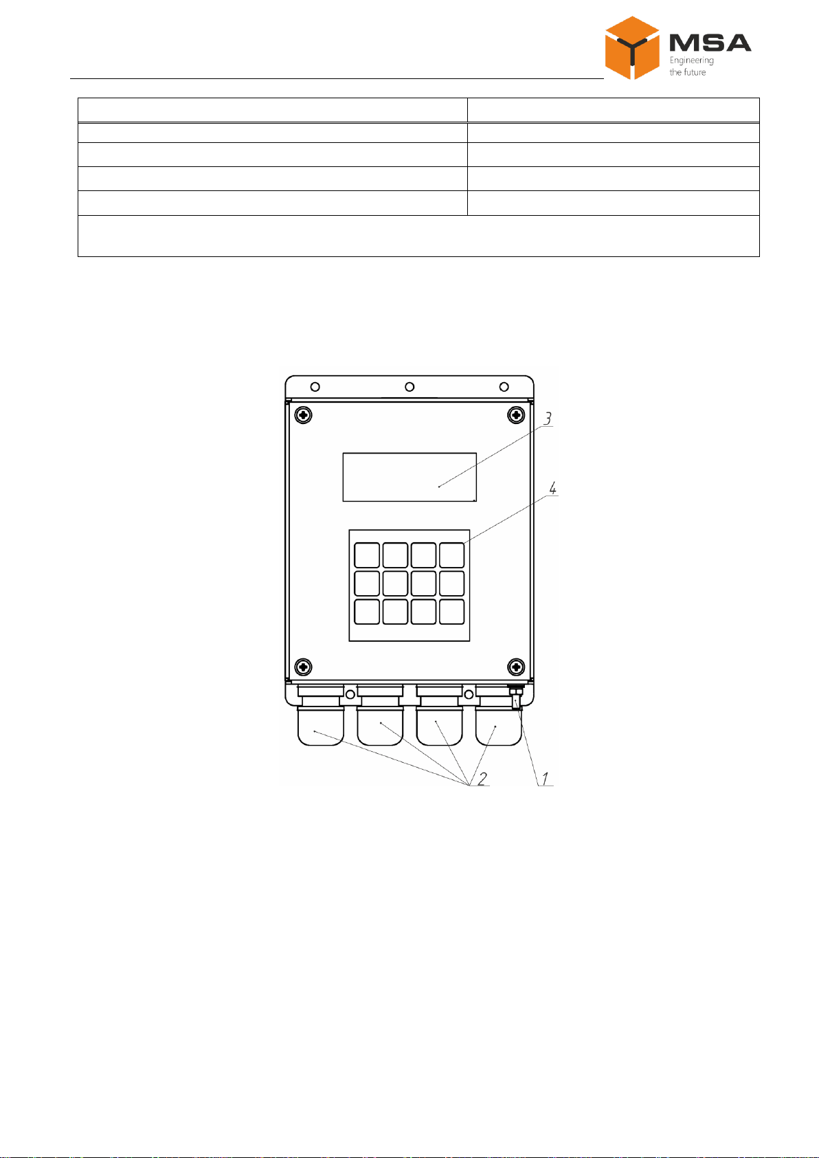
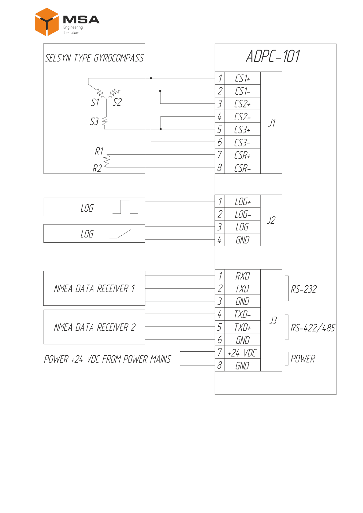
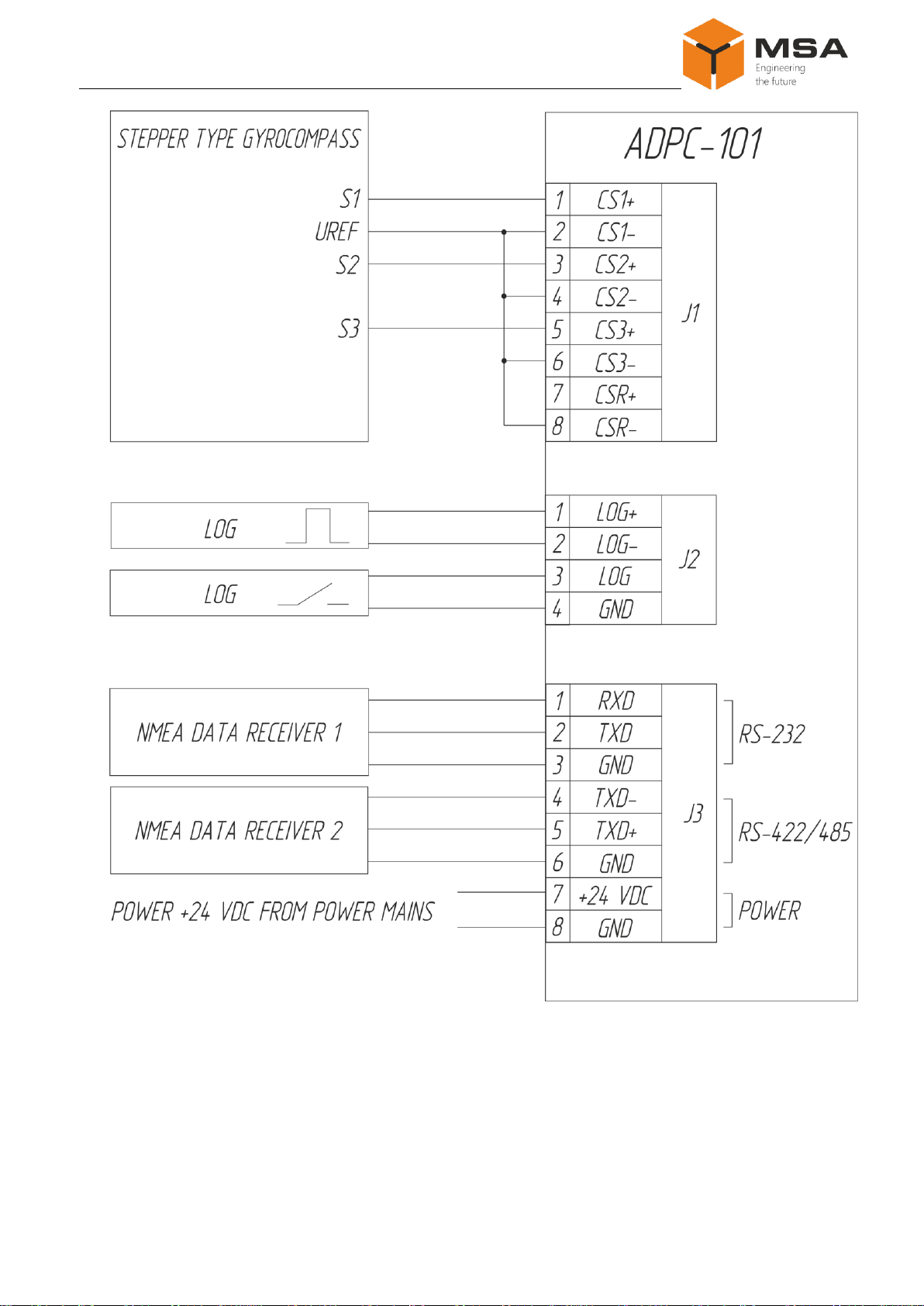
1.3 Structure and operation of the Product..................................................................................6
1.4 Measurement instruments, tools and appliances.................................................................13
1.5 Marking and sealing............................................................................................................14
1.6 Packaging............................................................................................................................14
2INTENDED USE OF THE PRODUCT..............................................................................15
2.1 Operational constraints........................................................................................................15
2.2 Usage preparations..............................................................................................................15
2.3 Usage of the product ...........................................................................................................16
3TECHNICAL SERVICE OF THE PRODUCT.................................................................22
3.1 General description .............................................................................................................22
3.2 Safety features.....................................................................................................................22
3.3 Maintenance routine............................................................................................................22
3.4 Preservation.........................................................................................................................23
4CURRENT REPAIR OF THE PRODUCT........................................................................24
4.1 General description .............................................................................................................24
4.2 Safety features.....................................................................................................................24
4.3 Current repair of the Product...............................................................................................24
5STORAGE.............................................................................................................................26
6TRANSPORTATION...........................................................................................................27
7DISPOSAL.............................................................................................................................28
8WARRANTY OBLIGATIONS...........................................................................................29
ANNEX A (MANDATORY) OUTLINE AND INSTALLATION DIMENSIONS...............30

Analog-to-digital converter
ADPC-101
3
INTRODUCTION
This operating manual (hereinafter referred to as OM) is intended to describe
structure, operating principles, technical service and usage of Analog-to-digital convert-
er ADPC-101 (hereinafter referred to as the Product, ADPC-101).
In addition to the instructions given in this document, the safety regulations and
rules applicable in the field shall be observed.
Only those who have read and understood this document and those who have
had special training shall be permitted to operate with the PSU according to the applica-
ble regulations.
Terms and abbreviations:
OM –operating manual;
S –software;
SC –short circuit;
ТS –technical service;
CL –check list;
LCD –liquid-crystal display;
ADPC-101 –analog-to-digital converter ADPC-101;
LFSG –large fine-pored silica gel granular.
NMEA (National Marine Electronics Association) –text communication pro-
tocol for interconnection of marine (normally navigational) equipment.
Synchro (Selsyn) –electrical AC self-synchronizing micromachines (for
smooth transmission of shaft degree).
Step (stepper) motor –synchronous brushless motor with several windings
where current supplied to one of stator’s windings causes rotor fixation. Sequential acti-
vation of motor windings causes discrete angular rotor movements (steps).
Selsyn and step (stepper) type –type of electric motor transmitting data on an-
gular displacement.

Operating manual
4 v.4.17
1DESCRIPTION AND OPERATION OF THE PRODUCT
1.1 DESCRIPTION
The Product ensures Analog-to-digital conversion of obsolete signals from gy-
rocompasses and logs in NMEA 0183 sentences and transmission of these data to the
corresponding navigational equipment.
The Product is used on the ships equipped with gyrocompasses and logs. They
do not output current data in NMEA 0183 sentences (IEC 61162) to navigational
equipment, which requires course and speed data in digital format. The Product may be
installed on communication ships due to their re-equipping with automatic identification
system and act as a connecting device converting data from obsolete compasses and
logs.
1.2 TECHNICAL SPECIFICATIONS
1.2.1 The Product performs the following functions:
a) Reception of current course data from gyrocompass with synchro or stepper
interface;
b)Reception of current speed data from logs with stepper interface or closing
contact interface;
c) Display of current speed and course data on the integrated LCD;
d)Conversion of received data into NMEA 0183 format (IEC 61162);
e) Transmission of the converted speed and course data as well as ship rate turn
via standard interface RS-232 and RS-422/485 to external equipment in NMEA 0183
format (IEC 61162).
Intuitive menu options and convenient keyboard enable user-friendly settings of
the operation modes.
The Product is manufactured in robust moisture-proof metal casing, which may
be mounted on bulkheads inside premises.
1.2.2 Types of connected equipment:
a) gyrocompasses:
SYNCHRO type gyrocompass;
STEPPER type gyrocompass;
b)logs:
stepper type log (pulse);

Analog-to-digital converter
ADPC-101
5
log with closing contact interface.
Technical specifications of the Product are represented in Table 1.
Table 1 –General technical specifications of the Product
Parameter
Value
Power supply
Input voltage with galvanic isolation, V DC
9.6…36.0
Power consumption, W
3
Input gyrocompass signals
Max. voltage, V
350
Gyro ratio
360х; 240х; 180х; 90х; 60х; 36х
Max. frequency, Hz
500
Max. rate of course change (rate of turn), °/s
80
Input log signals
Max. voltage, V
400
Pulse per mile
100; 200; 300; 400; 500; 600
Input parameters
Optoisolated inputs
+(except log with closing contact)
Switching threshold levels, V
3; 6
Output parameters
Number of asynchronous serial ports RS-232 and RS-
422/485 interface, pcs.
2
Parity bit
no; even; odd
Stop bits
1 or 2
Update frequency, Hz
1; 2; 5; 10
Output signal format
–standard line NMEA 0183 with check-
sum;
–63 variants of NMEA 0183 sentences
output (IEC 61162)*
Data bit, bit
8
Baud rate, bit/s
2400; 4800; 9600; 14400; 19200;
28800; 38400; 57600; 76800; 115200;
230400
Range of measured values
Speed, knots
0.0…99.9
Course
0.0°…359.9°
Data accuracy
Speed, knots
0.1
Course
0.1°
General specifications
Overall dimensions, mm
200×134×68

Operating manual
6 v.4.17
Parameter
Value
Protection degree
IP22
Limiting temperature, °С
–60…+70
Operating temperature, °С
–15…+55
Weight, kg
1.2
*Configured by means of three different options to output ship turn rate, current course and speed
data.
1.3 STRUCTURE AND OPERATION OF THE PRODUCT
1.3.1 The Product is manufactured in metal casing where a grounding stud and
connection ports are located, see Figure 1.
Figure 1 –ADPC-101 external view
The Product structure includes functional elements, see Table 2.

Analog-to-digital converter
ADPC-101
7
Table 2 –Functional elements
Pos. №
Elements
Type, standard size,
identifier
Description
1
Grounding stud
М4х15
Main point grounding element of the
Product
2
Cable gland
МG-16
To connect power supply and external
equipment
3
LCD
–
To display data
4
Functional keys
«1» and «F1»
«1» to enter digit «1» and,
«F1» to access the menu of course data
input
«2» and «F2»
«2» to enter digit «2» and,
«F2» to access display mode of distance
traveled on the LCD
«3» and « »
«3» to enter digit «3» and,
« » to navigate «up»in the menu
«4» and «F3»
«4» to enter digit «4» and,
«F3» to access settings menu
«5» and «+»
To enter digit «5» and «+»
«6» and « »
«6» to enter digit «6» and,
«» to navigate «left» in the menu
«7» and «.»
To enter digit «7» and «.»
«8» and « »
«8» to enter digit «8» and,
«» to navigate «right» in the menu
«9» and «–»
To enter digit «9» and «–»
«0» and « »
«0» to enter digit «0» and,
« » to navigate «down»in the menu
«SHIFT»
To change the case
«CLEAR» and
«ENTER»
«CLEAR» to confirm and,
«ENTER»to delete data in the menu
Note –See the positions on Figure 1.
1.3.2 Connection diagrams of the Product are represented in Figures 2–4; for
the layout and assignment of printed circuit board terminal connectors, see Figures 5
and Table 3.
To change switching threshold of log and gyrocompass optoisolated inputs, use
DIP-switches «J4», «J5», «J6», «J7», «J8», and jumpers (see Figure 5). If contacts are
closed, threshold input voltage is 6 V, if opened - 3 V.
Threshold voltage, if DIP-switches «J4», «J5», «J6», «J7», «J8» are opened and
closed, are represented below:
а) or –threshold voltage approx. 3 V;

Operating manual
8 v.4.17
b) –threshold voltage approx. 6 V.
DIP-switch «J10» status:
а) –ADPC-101 is an end device on
RS-422/485 channel;
b) –ADPC-101 is a middle device on
RS-422/485 channel.
Connectors «J9», «J1» (see Figure 5) are used for device configuration at manu-
facturing stage and not used during operation.

Analog-to-digital converter
ADPC-101
9
Figure 2 –Connection diagram of selsyn type gyromcompass

Operating manual
10 v.4.17
Figure 3 –Connection diagram of stepper type gyromcompass

Analog-to-digital converter
ADPC-101
11
Figure 4 –Connection diagram of stepper type gyrocompass with common positive

Operating manual
12 v.4.17
Figure 5 –Terminals layout on the Product’s printed circuit board
Table 3 –Assignment of the Product’s port terminals
Connector
Terminal №
Description
«J1»
«CS1+»
To connect gyrocompass
«CS1–»
«CS2+»
«CS2–»
«CS3+»
«CS3–»
«CSR+»
«CSR–»
«J2»
«LOG+»
To connect log
«LOG–»
«LOG»
«GND»

Analog-to-digital converter
ADPC-101
13
Connector
Terminal №
Description
«J3»
«RX»
To connect data receivers
«TX»
«GND»
«TX–»
«TX+»
«GND»
«+24V»
To connect power supply
«GND»
1.4 MEASUREMENT INSTRUMENTS,TOOLS AND APPLIANCES
Consumables required for the TS are represented in Table 4.
Table 4 –Consumables required for the TS
Name and identifier of consumables
Amount of
consumables
Note
Cleaning cloth
0.10 kg
1To clean the Product’s sur-
face –use clean cloth;
2To remove severe contami-
nation –use cloth soaked in
alcohol.
Rectified hydrolytic technical ethyl alcohol
0.05 l
To soak cloth and remove
contamination from screen
Varnish
0.05 kg
To cover surfaces of the
Product in case of paint coat-
ing damage
Abrasive cloth
0.06 х 0.06 m
To polish surfaces of the
Product in case of paint coat-
ing damage

Operating manual
14 v.4.17
1.5 MARKING AND SEALING
The Product has a nameplate indicating name, input voltage, power consump-
tion, protection degree, weight, serial number and date of manufacturing.
The sealing of the Product is not provided.
1.6 PACKAGING
At the time of delivery the Product is packed in a corrugated board box and in-
ner packaging (air bubble film) ensuring its transportation and storage at the warehouse.
Transport packaging is also used as a returnable packaging for transportation of
the Product to the repair location and back.
The sealing of transport packaging is not provided.

Analog-to-digital converter
ADPC-101
15
2INTENDED USE OF THE PRODUCT
2.1 OPERATIONAL CONSTRAINTS
Select the installation site in compliance with operational constraints (operating
temperature and protection degree –IP).
Caution! Distance between the installation site and magnetic compass shall
not be less than 1 m!
2.2 USAGE PREPARATIONS
2.2.1 Safety features
While preparing the Product for operation, check it visually after unpacking;
mechanical damage shall be absent.
Connection to power mains shall be provided only in compliance with input
power requirements.
Before connecting the Product shall be switched off and have a proper ground-
ing.
While using the Product the staff shall follow “The technical rules for operation
of electric installation” and “Safety rules for operation of electric installation” while
testing electrical circuits and insulation resistance.
2.2.2 Visual check procedure
Before switching the Product on:
a) check visually integrity and initial position of the controls;
b)check absence of dust and dirt on the Product casing; clean with a soft cloth if
necessary, see Table 4;
c) check that cable connectors are securely connected to the Product and reliable
grounding.
2.2.3 Switching on instructions. While connecting the Product and preparing it
for operation follow the steps below:
a) transfer circuit breakers of main power switchboard to «OFF» position;
b)connect de-energized cables to the Product;
c) transfer circuit breakers of main power switchboard to «ON» position;
d)enter initial course data and used types of gyrocompass and log, for more in-
formation see Ошибка! Источник ссылки не найден..

Operating manual
16 v.4.17
2.2.4 To switch the Product off:
a) transfer circuit breakers of main power switchboard to «OFF» position;
b)disconnect de-energized cables.
2.3 USAGE OF THE PRODUCT
2.3.1 As soon as power is supplied, the Product transfers to the mode of course
and speed data display; herewith gyrocompass and log readings are displayed as zeroes,
see Figure 6. Signal is absent on the converter’s output. The Product requires an input of
initial course values and gyrocompass and log types.
Unless initial course values and types of gyrocompass and log are entered, the
Product will stay in waiting mode, and alarm will work.
To ensure proper operation, select gyrocompass type and log type in the menu set-
tings, see 2.3.8 and 2.3.9, and input manually current course data of used gyrocompass.
If received compass and log data are invalid, the display shows «?»(a question
mark) –in the beginning of the relevant line.
Figure 6 –Display mode of current course and speed data from gyrocompass and log
Note –Re-input current gyrocompass data if type of gyrocompass is changed
(stepper or synchro).
2.3.2 If initial course values input is required, select relevant settings in «Need
Enter Gyro»menu item. If «Yes»is selected, provide settings according to 2.3.3. If
«No» is selected, the Product will output NMEA 0183 sentences (speed data) after
switching on, if settings according to 2.3.8,d) were provided.
2.3.3 To input initial course data:
a) Take readings from a gyrocompass connected to the Product;
b)press button «1» on the Product casing; the command to enter course data will
appear on the display, see Figure 7;
Figure 7 –Course data input

Analog-to-digital converter
ADPC-101
17
c) enter course data using digit buttons and point «.»;
d)press «ENTER».
The LCD returns into display mode of current course data from gyrocompass
and log; sound signaling stops.
To edit or delete the last character of the input value, you may use «CLEAR»
button.
Buttons «.»and «CLEAR»are entered in upper case; note that after pressing «.»
the case automatically becomes a lower one; after pressing «CLEAR»the case remains
upper.
To change the case, use «SHIFT».
The case may be defined by a cursor status:
blinking cursor with highlighted character space –lower case;
not blinking cursor (underlining) –upper case.
Caution! All configured options are saved into the non-volatile memory; they
are not changed in case of power failure. Gyrocompass course data and distance trav-
eled are set to zero. Input new current course data from the connected compass to en-
sure correct Product operation.
Notes
1In this settings mode a user may input a floating point number with one deci-
mal place of a tenth. Invalid values (more than 359.9) will be ignored.
2If «unuse timeout»option was selected (in position «5s»; «10s»; «15s»;
«20s»; «25s»except «OFF»), and a user provides no settings or actions, the Product au-
tomatically switches from an input mode to course and speed data display mode without
any option changes.
3Selected options are saved only after pressing «ENTER».
As soon as log and gyrocompass type are selected, initial course data are en-
tered, and valid data are received, the Product starts to output NMEA 0183 (IEC 61162)
signal to both outputs RS-232 and RS-422/485 at the same time, with the frequency
configured in the Product’s settings.
Sample input
1To enter 320.3 degrees, press the buttons:

Operating manual
18 v.4.17
«1» «3» «2» «0» «SHIFT»«.» «3» «ENTER»
2To enter 152.4 and then change digit 2 to 8, press:
«1»«1»«5»«2»«SHIFT»«.»«4»«SHIFT»«CLEAR»«CLEAR»
«CLEAR» «8»«SHIFT» «.» «4» «ENTER».
2.3.4 In the mode of additional display of inputs status, LCD shows logic signal
states on the Product inputs, which might be useful during installation operations, see
Figure 8.
Figure 8 –Additional mode to display inputs status
To switch to the additional mode, press «9».
For optoisolated input:
a) logic «0» means that signal level is lower than switching threshold;
b)logic «1» means that signal level exceeds switching threshold.
c) «123» – 1, 2, 3 windings of selsyn gyrocompass.
For log’s input with closing contact interface:
a) logic «0» means that contact is opened;
b)logic «1» means that contact is closed.
The Product will stay in this mode unless an operator presses any button.
2.3.5 In traveled distance display mode LCD shows traveled distance since the
last time a distance recorder was set to zero. Zeroing occurs when the Product is
switched off, or may be carried out by an operator by pressing «7». When the Product
switches to traveled distance mode, an upper line of LCD with speed data is replaced by
traveled distance data line, see Figure 9.
Figure 9 –Traveled distance display mode
To switch to this mode, press «F2». To exit the mode, press «F2» again.
Speed and course data transmission in NMEA 0183
(IEC 61162) format to converter’s outputs in this mode is not interrupted or changed.

Analog-to-digital converter
ADPC-101
19
2.3.6 In mode of current ship turn rate display LCD shows current ship turn
rate. When switching to this mode, the LCD lower line with current course data starts
showing ship rate turn data, see Figure 9.
To switch to the mode, press button «3». To exit the mode, press «3» again.
2.3.7 Press «F3» to access the settings menu.
To navigate in the menu, use buttons «3», «0», which ensure movement «up»
and «down», respectively. To select values, use buttons «6», «8», which ensure move-
ment «left» and «right», respectively.
To exit the mode, press «F3»again. To select the values (options), press «EN-
TER».
To review software version, press «0».
2.3.8 Gyrocompass settings:
a) GYRO ratio –ratio between selsyn turn and ship turn: 360x, 240x, 180x,
90x, 60x, 36x;
b)GYRO sign –direction of compass rotation: positive, negative;
c) GYRO type –gyrocompass type: selsyn, stepper.
Note –When switching types of gyrocompass (stepper or selsyn), re-enter cur-
rent compass data;
d)GYROref polarity –select of signal polarity: positive, negative:
select of negative polarity for selsyn gyrocompasses leads to signal inversion
and consequently operation with displacement for 180°.
For stepper gyrocompass positive polarity matches high signal level, nega-
tive –low signal level, which defines operating mode of gyrocompass.
2.3.9 Log settings:
а) LOG pulse / mile –a number of pulses per mile: 100,200,300,400,500,600.
Note –If log’s pulse repetition interval at the moment exceeds information up-
date interval (1s), the speed is calculated according to current accumulated measurement
after the last log pulse;
b) LOG bounce delay –time for software treatment of contact bounce:
0, 2, 10, 20, 30, 40, 50, 70, 100 ms.
2.3.10 Settings of serial port:

Operating manual
20 v.4.17
a) COM baudrate –baudrate: 2400, 4800, 9600, 14400, 19200, 28800, 38400,
57600, 76800, 115200, 230400 bit/s;
b)COM parity –parity bit: NO, EVEN, ODD;
c) COM stop bits –stop bits: 1, 2.
2.3.11 Keyboard setting “Button click”–sound key stroke: Yes, No.
2.3.12 Display setting “Display refresh”–frequency of screen update:
1, 2, 5 and 10 Hz.
2.3.13 Setting of “Unuse timeout”(operator’s inactivity) –time until automatic
backlight switch off, menu exit or exit from input mode in case of operator inactivity: 5,
10, 15, 20, 25 s, OFF (timeout is switched off).
2.3.14 “Alarm”settings –function of alarm signaling in case of invalid data
from gyrocompass and (or) log, as well as no input of initial course data: ON (alarm is
switched on), OFF (alarm is switched off).
2.3.15 NMEA 0183 settings:
a) NMEA REFRESH –update frequency of output data: 1, 2, 5 and 10 Hz.
b) NMEA ROT fmt –formats of output line of ship turn rate:
Disabled –no output line;
TIROT –$TIROT,x.x,A*cs;
HNROT –$HNROT,x.x,A*cs;
c) NMEA GYRO fmt –formats of output line of current course data:
Disabled –no output line;
AGHDT –$AGHDT,x.x,T*cs;
HEHDT –$HEHDT,x.x,T*cs;
HCHDT –$HCHDT,x.x,T*cs;
SIVHW –$SIVHW,x.x,T,,,x.x,N,,*cs (mixed format –course and speed are
output in one line);
d)NMEA LOG fmt –formats of output line of current speed data:
Disabled –no output line;
VMVTG - $VMVTG,,,,,x.x,N,,*cs;
VMVBW - $VMVBW,x.x,,A,,,*cs (NMEA v 2.0);
Table of contents