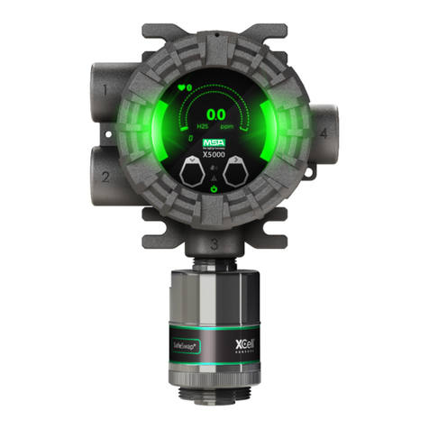
MSA Ultima User manual

Ultima® with Digital
Output Gas Monitor
instruction manual
º
WARNING
THIS MANUAL MUST BE CAREFULLY READ BY ALL INDIVIDUALS WHO
HAVE OR WILL HAVE THE RESPONSIBILITY FOR USING OR SERVICING THE
PRODUCT. Like any piece of complex equipment, the unit will perform as
designed only if it is installed, used and serviced in accordance with the
manufacturer’s instructions. OTHERWISE IT COULD FAIL TO PERFORM AS
DESIGNED AND PERSONS WHO RELY ON THIS PRODUCT FOR THEIR
SAFETY COULD SUSTAIN SEVERE PERSONAL INJURY OR DEATH.
The warranties made by Mine Safety Appliances Company with respect to the
product are voided if the product is not used and serviced in accordance with
the instructions in this manual. Please protect yourself and others by following
them. We encourage our customers to write or call regarding this equipment
prior to use or for any additional information relative to use or repairs.
In the U.S., to contact your nearest stocking location, dial toll-free 1-800-MSA-INST.
To contact MSA International, dial 1-412-967-3354.
© COPYRIGHT MINE SAFETY APPLIANCES COMPANY 2003 - All Rights Reserved
This manual is available on the internet at www.msanet.com
Manufactured by
MSA INSTRUMENT DIVISION
P.O. Box 427, Pittsburgh, Pennsylvania 15230
(L) Rev 3 710471

MSA Permanent Instrument Warranty
1. Warranty- Seller warrants that this product will be free
from mechanical defect or faulty workmanship for a period
of eighteen (18) months from date of shipment or one (1)
year from installation, whichever occurs first, provided it is
maintained and used in accordance with Seller’s
instructions and/or recommendations. This warranty does
not apply to expendable or consumable parts whose
normal life expectancy is less than one (1) year such as,
but not limited to, non-rechargeable batteries, filament
units, filter, lamps, fuses etc. The Seller shall be released
from all obligations under this warranty in the event
repairs or modifications are made by persons other than
its own or authorized service personnel or if the warranty
claim results from physical abuse or misuse of the
product. No agent, employee or representative of the
Seller has any authority to bind the Seller to any
affirmation, representation or warranty concerning the
product. Seller makes no warranty concerning
components or accessories not manufactured by the
Seller, but will pass on to the Purchaser all warranties of
manufacturers of such components. THIS WARRANTY IS
IN LIEU OF ALL OTHER WARRANTIES, EXPRESSED,
IMPLIED OR STATUTORY, AND IS STRICTLY LIMITED
TO THE TERMS HEREOF. SELLER SPECIFICALLY
DISCLAIMS ANY WARRANTY OF MERCHANTABILITY
OR OF FITNESS FOR A PARTICULAR PURPOSE.
2. Exclusive Remedy- It is expressly agreed that Purchaser’s
sole and exclusive remedy for breach of the above
warranty, for any tortious conduct of Seller, or for any
other cause of action, shall be the repair and/or
replacement at Seller’s option, of any equipment or parts
thereof, which after examination by Seller is proven to be
defective. Replacement equipment and/or parts will be
provided at no cost to Purchaser, F.O.B. Seller’s Plant.
Failure of Seller to successfully repair any nonconforming
product shall not cause the remedy established hereby to
fail of its essential purpose.
3. Exclusion of Consequential Damage- Purchaser
specifically understands and agrees that under no
circumstances will seller be liable to purchaser for
economic, special, incidental or consequential damages
or losses of any kind whatsoever, including but not limited
to, loss of anticipated profits and any other loss caused by
reason of nonoperation of the goods. This exclusion is
applicable to claims for breach of warranty, tortious
conduct or any other cause of action against seller.
General Warnings and Cautions
º
WARNINGS
1. The Ultima with Digital Output Gas Monitor described in
this manual must be installed, operated and maintained in
strict accordance with its labels, cautions, warnings,
instructions, and within the limitations stated.
2. Keep cover tightly closed when power is applied on an
explosion-proof model; otherwise, ignition of a hazardous
atmosphere can occur. Before removing the cover for
maintenance or calibration, ensure the surrounding
atmosphere is and remains free of toxic or combustible
gases until the cover is closed.
3. The Ultima with Digital Output Gas Monitor is designed to
detect gases or vapors in air. It cannot measure the
concentration of gases or vapors in steam or inert or
oxygen-deficient atmospheres. The oxygen sensor can
measure oxygen-deficient atmospheres.
4. Electrochemical sensors are sealed units which contain a
corrosive electrolyte. Should a sensor develop leakage, it
must be immediately removed from service; then, remove it
from the sensing head and discard it properly. Caution must
be exercised so that the electrolyte does not contact skin,
eyes, clothing or circuitry; otherwise, serious personal injury
(burns) and/or equipment damage may result.
5. Use only genuine MSA replacement parts when
performing any maintenance procedures provided in this
manual. Failure to do so may seriously impair instrument
performance. Repair or alteration of the Ultima with Digital
Output Gas Monitor, beyond the scope of these
maintenance instructions or by anyone other than a
authorized MSA service personnel, could cause the
product to fail to perform as designed and persons who
rely on this product for their safety could sustain serious
personal injury or death.
6. Do not locate the general-purpose enclosure models in an
area which may contain a flammable mixture of gas and
air; otherwise, an explosion may occur. The
general-purpose Ultima with Digital Output Gas Monitors
can be a source of ignition and must not be mounted in an
area where a flammable mixture of combustible gas and

air may be present; otherwise, an explosion may occur. If
such a location must be monitored, use an explosion-proof
Ultima with Digital Output Gas Monitor model.
7. The Ultima with Digital Output Gas Monitor is designed to
be connected to and operate within a LonWorks®
Network. The monitor is incompatible and will not work
with other types of networks.
8. For proper operation, the Ultima with Digital Output Gas
Monitor must be installed and configured properly.
There are third party installation and configuration
tools available.
9. This device contains transmitter module FCC
ID:OUR9XSTREAM. The enclosed device complies with
Part 15 of the FCC Rules. Operation is subject to the
following conditions: (1) This device may not cause
harmful interference, and (2) this device must accept any
interference received, including interference that may
cause undesired operation.
In order to comply with the FCC RF exposure requirements,
this unit may be used only with Approved Antennas that
have been tested with this radio. A minimum separation
distance of 20 cm must be maintained from the antenna to
any nearby persons. Changes or modifications to the
radio or antenna could void the user’s authority to operate
this product.
Failure to follow the above can result in serious personal injury
or death.
º
CAUTIONS
1. As with all gas monitors of these types, high levels of, or
long exposure to, certain compounds in the tested
atmosphere could contaminate the sensors. In
atmospheres where an Ultima with Digital Output Gas
Monitor may be exposed to such materials, calibration
should be performed frequently to ensure that operation is
dependable and display indications are accurate.
2. The Ultima with Digital Output Gas Monitor must not be
painted. If painting in an area where a Monitor is located,
ensure that paint is not deposited on the sintered, metal
flashback arrestor in the inlet fitting of the Ultima with
Digital Output Gas Monitor, if so equipped. Such paint
deposits would interfere with the diffusion process,

whereby a sample of the atmosphere being monitored
diffuses into the Monitor.
3. The only absolute method to ensure proper overall
operation of an Ultima with Digital Output Gas Monitor is
to check it with a known concentration of the gas for which
it has been calibrated. Consequently, calibration checks
must be included as part of the routine inspection of the
system.
4. Protect the Ultima with Digital Output Gas Monitor from
extreme vibration. Do not mount the sensing head in
direct sunlight as this may cause overheating of
the sensor.
Failure to follow the above can result in serious personal injury
or death.

Table of Contents
Chapter 1
General Description . . . . . . . . . . . . . . . . . . . . . . . . . 1-1
General . . . . . . . . . . . . . . . . . . . . . . . . . . . . . . . . . . . . . . . . . . . . . . . . . . . . 1-1
This Manual . . . . . . . . . . . . . . . . . . . . . . . . . . . . . . . . . . . . . . . . . . . . . . . . 1-1
Unpacking Your Unit . . . . . . . . . . . . . . . . . . . . . . . . . . . . . . . . . . . . . . . . . 1-1
General Description . . . . . . . . . . . . . . . . . . . . . . . . . . . . . . . . . . . . . . . . . . 1-2
Identifying Your Unit . . . . . . . . . . . . . . . . . . . . . . . . . . . . . . . . . . . . . . . . . . 1-2
If Unit to be used with the Optional Ultima Duct Mount Kit . . . . . . . . . . . . 1-3
If Unit Powered with the Optional Power Supply Module . . . . . . . . . . . . . 1-3
To Determine Your Sensor Type . . . . . . . . . . . . . . . . . . . . . . . . . . . . . . . . 1-3
Hazardous Area Rating . . . . . . . . . . . . . . . . . . . . . . . . . . . . . . . . . . . . . . . 1-3
Chapter 2
Network and Ultima with
Digital Output Gas Monitor Variables . . . . . . . . . . 2-1
General . . . . . . . . . . . . . . . . . . . . . . . . . . . . . . . . . . . . . . . . . . . . . . . . . . . . 2-1
Network Configuration . . . . . . . . . . . . . . . . . . . . . . . . . . . . . . . . . . . . . . . . 2-1
Ultima with Digital Output Gas Monitor Configuration . . . . . . . . . . . . . . . . 2-1
Types of Variables . . . . . . . . . . . . . . . . . . . . . . . . . . . . . . . . . . . . . . . . . . . 2-2
Ultima with Digital Output Gas Monitor Network Variables . . . . . . . . . . . . 2-2
Node Object (Type 0) Variables . . . . . . . . . . . . . . . . . . . . . . . . . . . . . . . . . 2-2
Table 2-1. Object (Type 0) Variables . . . . . . . . . . . . . . . . . . . . . . . . . . 2-3
Variable #1 - nviRequest . . . . . . . . . . . . . . . . . . . . . . . . . . . . . . . . . . . . . 2-3
Variable #2 - nvoStatus . . . . . . . . . . . . . . . . . . . . . . . . . . . . . . . . . . . . . . . 2-4
Variable #3 - nciNetConfig . . . . . . . . . . . . . . . . . . . . . . . . . . . . . . . . . . . . . 2-4
Variable #4 - nciMaxStsSendT . . . . . . . . . . . . . . . . . . . . . . . . . . . . . . . . . 2-4
Variable #5 - nviTimeSet . . . . . . . . . . . . . . . . . . . . . . . . . . . . . . . . . . . . . . 2-4
Open Loop Sensor Object (Type 1) Variables . . . . . . . . . . . . . . . . . . . . . 2-5
Table 2-2. Open Loop Object (Type 1) Variables . . . . . . . . . . . . . . . . 2-5
Variable #1 - nvoValue . . . . . . . . . . . . . . . . . . . . . . . . . . . . . . . . . . . . . . . . 2-6
Variable #2 - nvoRawHwData . . . . . . . . . . . . . . . . . . . . . . . . . . . . . . . . . . 2-6
Variable #3 - nciMinDelta . . . . . . . . . . . . . . . . . . . . . . . . . . . . . . . . . . . . . . 2-6
Variable #4 - nciMaxSendT . . . . . . . . . . . . . . . . . . . . . . . . . . . . . . . . . . . . 2-6
Table of Contents
TOC-1

Variable #5 - nciMinSendT . . . . . . . . . . . . . . . . . . . . . . . . . . . . . . . . . . . . 2-6
Ultima with Digital Output Gas Monitor’s Variables . . . . . . . . . . . . . . . . . 2-6
Table 2-3. Variable Definitions . . . . . . . . . . . . . . . . . . . . . . . . . . . . . . 2-7
Chapter 3
Installation and Start-up . . . . . . . . . . . . . . . . . . . . . 3-1
Mounting Your Gas Monitor . . . . . . . . . . . . . . . . . . . . . . . . . . . . . . . . . . . 3-1
Electrical Connections for
Ultima with Digital Output Gas Monitors . . . . . . . . . . . . . . . . . . . . . . . . . . 3-1
General Wiring Information . . . . . . . . . . . . . . . . . . . . . . . . . . . . . . . . . . . . 3-1
º
WARNING . . . . . . . . . . . . . . . . . . . . . . . . . . . . . . . . . . . 3-1
Cable Requirements . . . . . . . . . . . . . . . . . . . . . . . . . . . . . . . . . . . . . . . . . 3-2
º
WARNING. . . . . . . . . . . . . . . . . . . . . . . . . . . . . . . . . . . . 3-2
º
WARNING. . . . . . . . . . . . . . . . . . . . . . . . . . . . . . . . . . . . 3-2
Table 3-1. Maximum Cable Length . . . . . . . . . . . . . . . . . . . . . . . . . . . . 3-2
Table 3-2. Maximum Separation Distance . . . . . . . . . . . . . . . . . . . . . . 3-3
Power Requirements . . . . . . . . . . . . . . . . . . . . . . . . . . . . . . . . . . . . . . . . . 3-3
º
WARNING. . . . . . . . . . . . . . . . . . . . . . . . . . . . . . . . . . . . 3-3
Table 3-3. Wire Harness Assembly (Wired Units) . . . . . . . . . . . . . . . . 3-4
Table 3-4. Wire Harness Assembly (Wireless Units) . . . . . . . . . . . . . . 3-4
Figure 3-1. Wire Harness Assembly (Wired Unit Shown) . . . . . . . . . 3-4
º
WARNING. . . . . . . . . . . . . . . . . . . . . . . . . . . . . . . . . . . . 3-5
Wiring the Ultima with Digital Output Gas Monitor
Without Using the Wiring Harness . . . . . . . . . . . . . . . . . . . . . . . . . . . . . . 3-5
Table 3-5. Lower Printed Circuit Board TB1 Connections (Wired Units) . 3-5
Table 3-6. Power Requirements . . . . . . . . . . . . . . . . . . . . . . . . . . . . . . 3-6
Table 3-7. Lower Printed circuit board connections (Wireless) . . . . . . 3-6
Figure 3-2. Bottom Printed Circuit Board . . . . . . . . . . . . . . . . . . . . . . 3-6
Figure 3-3. Routing the Antenna Cable . . . . . . . . . . . . . . . . . . . . . . . . 3-6
Figure 3-4. Communication Wiring Connections . . . . . . . . . . . . . . . . 3-7
Electrical Connections for the Ultima with Digital Output Gas Monitor Re-
mote Sensor Module . . . . . . . . . . . . . . . . . . . . . . . . . . . . . . . . . . . . . 3-7
º
WARNING. . . . . . . . . . . . . . . . . . . . . . . . . . . . . . . . . . . . 3-7
º
WARNING. . . . . . . . . . . . . . . . . . . . . . . . . . . . . . . . . . . . 3-8
Electric Connections for Combustible Models . . . . . . . . . . . . . . . . . . . . . 3-8
Table of Contents
TOC-2

Start-up of the
Ultima with Digital Output Gas Monitor . . . . . . . . . . . . . . . . . . . . . . . . . . . 3-9
Applying Power to the Ultima with Digital Output Gas Monitor . . . . . . . . . 3-9
Calibrating the Ultima with Digital Output Gas Monitor . . . . . . . . . . . . . . . 3-9
Ultima with Digital Output Gas Monitor Configuration . . . . . . . . . . . . . . . . 3-9
Network Operation . . . . . . . . . . . . . . . . . . . . . . . . . . . . . . . . . . . . . . . . . . . 3-9
Setting the Wireless Channel for Ultima Units . . . . . . . . . . . . . . . . . . . . . . 3-9
Table 3-8. Wireless Channel Selection . . . . . . . . . . . . . . . . . . . . . . . . 3-10
Figure 3-5. Routing the Antenna Cable . . . . . . . . . . . . . . . . . . . . . . . 3-10
Chapter 4
Maintenance . . . . . . . . . . . . . . . . . . . . . . . . . . . . . . . 4-1
Maintenance . . . . . . . . . . . . . . . . . . . . . . . . . . . . . . . . . . . . . . . . . . . . . . . . 4-1
Obtaining Replacement Parts . . . . . . . . . . . . . . . . . . . . . . . . . . . . . . . . . . 4-1
º
WARNING. . . .. . . . . . . . . . . . . . . . . .. . . . . . . . . . . . . . 4-1
Table 4-1. Replacement Sensor Kits . . . . . . . . . . . . . . . . . . . . . . . . . . . 4-2
Ultima RF Digital Network Module Antenna Replacement . . . . . . . . . . 4-3
Table of Contents
TOC-3

Chapter 1
General Description
General
The Ultima with Digital Output Gas Monitor is designed to
connect to an integrated system of wired/wireless, compatible
network devices.
NOTE: The Ultima with Digital Output Gas Monitor can only be
used with a LonWorks network.
You must be familiar with the Chapter 2 network parameters if
you intend to use the Ultima with Digital Output Gas Monitor:
•in your own LonWorks network or
•in a setup other than the Ultima with Digital Output Gas Monitor
default setup.
The Ultima with Digital Output Gas Monitor provides long-distance
interconnect ability for:
•many Ultima with Digital Output Gas Monitors
•other network compatible devices.
This Manual
•is to be used with (and often refers to) the Ultima Gas Monitor
Instruction Manual (P/N 813161).
•contains a brief description of network variables for the Ultima
with Digital Output Gas Monitor; for a more complete
description of the entire network, refer to the system or
network manual.
Unpacking Your Unit
Upon receipt, ensure that your package contains:
•One Ultima Gas Monitor Instruction Manual (P/N 813161)
in addition to this manual (P/N 710471)
•One Ultima Gas Monitor
(see Ultima Gas Monitor manual FIGURE 1-1)
•One Ultima Remote Sensor Module; if equipped as a dual-
condulet model, see Ultima Gas Monitor manual FIGURE 1-2.
Chapter 1, General Description
1-1

General Description
The Ultima with Digital Output Gas Monitor is designed to sample
the environment (where mounted) and alert you to potentially
dangerous levels of one of the following gases, depending on
your particular model:
•Combustible gas •Hydrogen Cyanide
•Oxygen •Hydrogen Chloride
•Carbon Monoxide •Nitric Oxide
•Hydrogen Sulfide •Nitrogen Dioxide
•Chlorine •Sulfur Dioxide
The unit is shipped ready for installation with an external wiring
harness to be connected to power and/or to the network. This
wiring harness eliminates the need to open the enclosure for
installation or operation.
Identifying Your Unit
There are five wired versions of the Ultima with Digital Output
Gas Monitor, all housed in rugged, aluminum enclosures
designed to meet NEMA 4X standards. There are three wireless
versions of the Ultima with Digital Output Gas Monitor, housed in
a 316 Stainless Steel enclosure designed to meet
general-purpose applications. Be sure to install the properly-rated
unit in any classified or certified area:
•Five versions are available in GENERAL-PURPOSE housings
(see Ultima Gas Monitor manual FIGURE 1-1):
•Toxic Gases (Wired units)
•Oxygen (Wired units)
•Combustible (Wireless units)
•Toxic (Wireless units)
•Oxygen (Wireless units).
•Three versions are available in EXPLOSION-PROOF housings
certified for Classification I, Groups B, C and D, Division 1,
Hazardous Locations:
•Combustible Gas (Wired units)
(see Ultima Gas Monitor manual FIGURE 1-3)
•Certain Toxic Gases (Wired units)
(see Ultima Gas Monitor manual FIGURE 1-4)
•Oxygen (Wired units)
(see Ultima Gas Monitor manual FIGURE 1-4)
Chapter 1, General Description
1-2

•All five versions are available as dual condulet models
(see Ultima Gas Monitor manual FIGURE 1-2)
If Unit to be used with the Optional Ultima Duct Mount Kit
•refer to Ultima Gas Monitor manual Appendix A.
If Unit Powered with the Optional Power Supply Module
•refer to Ultima Gas Monitor manual Appendix B.
To Determine Your Sensor Type
•Check the shipping carton
(see Ultima Gas Monitor manual FIGURE 1-5) or
•Check the sensor ID label located on the sensor cover or on the
condulet enclosure body (see Ultima Gas Monitor manual
FIGURE 1-6). This label identifies:
•Sensor supplied:
•Ultima Gas Monitor
•Ultima Gas Monitor Less Sensor or
•Ultima Remote Sensing Module.
•Type of gas:
•combustible gas
•toxic gas or
•oxygen.
•Range:
•% LEL
•PPM (parts per million) or
•%.
•Output:
•frequency
•multiplex
•digital
•4 to 20 mA or
•wireless.
Hazardous Area Rating
NOTE: Some models of the Ultima with Digital Output Gas
Monitor can be used in hazardous atmospheres
when installed according to the National Electric
Code, for Classification I, Groups B, C and D,
Division 1, Hazardous Locations. The larger metal
Chapter 1, General Description
1-3

Approval Label on the main enclosure body (see
Ultima Gas Monitor manual FIGURE 1-7) indicates if
your model is approved for use in hazardous areas.
Chapter 1, General Description
1-4

Chapter 2
Network and Ultima with Digital
Output Gas Monitor Variables
General
This chapter provides a more in-depth description of network
operation and setup of the Ultima with Digital Output Gas
Monitor. If you are using the default values and connecting the
monitor to a standard network, skip this chapter and proceed to
Chapter 3, "Installation and Start-up."
Network Configuration
The network can be an open-standard wiring architecture
type. Each Ultima with Digital Output Gas Monitor is considered a
node on the network with communication between nodes at a
reliable, efficient (78KB/s Wired and 19.5KB/s Wireless) rate. In
peer-to-peer communications:
•each node can communicate with every other network node
•no central, expensive supervisory controllers or computers
are needed.
Network protocol is embedded in each Ultima with Digital Output
Gas Monitor’s firmware for completely transparent operation. The
protocol:
•manages the internal communication within the monitor
•constructs and delivers all network communication.
To help network communications, each Ultima with Digital Output
Gas Monitor has data collision detection and
avoidance algorithms built-in to ensure the most reliable gas
monitor communication.
Ultima with Digital Output
Gas Monitor Configuration
Every Ultima with Digital Output Gas Monitor sends and receives
digital data in the form of network variables. These variables
correspond to real-world physical quantities such as:
•gas concentrations
Chapter 2, Ultima with Digital Output Gas Monitor
2-1

•alarm levels
•auto-calibrations
•other information can be viewed from a central monitoring
device, such as a personal computer:
•minimum
•maximum
•average
•date of last calibration.
Types of Variables
•Gas concentrations are outputs-only.
•Time-setting variable is an input for setting via the network.
•Object (Type 0) Variables control the network interface for the
Ultima with Digital Output Gas Monitor.
•All variables (except configuration, output and network-specific
variables) can be changed by the Ultima Gas Monitor
Controller; see manual (P/N 813379) for more details.
Ultima with Digital Output Gas Monitor
Network Variables
All variables can be polled, and those labeled as inputs can be
written by the network. Per Interoperability Guidelines, the
network interface incorporates:
•Mandatory Node Object Variables
•Mandatory Open Loop Sensor Object Variables
All variables are associated with one of these two objects and
are classified as either:
•configuration type variables or
•non-configuration type variables.
In addition to the mandatory network variables, a
non-interoperability interface is included, utilizing both Standard
Network Variable Types (SNVT’s) and non-SNVT structures to
satisfy additional requirements. These variables are listed in
TABLE 2-3.
Node Object (Type 0) Variables
The network can monitor these functions within the node or
sensor to be monitored.
Chapter 2, Ultima with Digital Output Gas Monitor
2-2

For initial implementation of the Ultima with Digital Output Gas
Monitor, only mandatory variables and certain optional variables
must be configured.
Unsupported status bits are to be marked in the status mask as
described in the following:
Table 2-1. Object (Type 0) Variables
VARI-
ABLE
#VARIABLE
NAME I/O FORMAT SNVT
#TYPE COMMENTS
1nviRequest ISNVT_obj_request 92 MAND*
Used to request
object modes
Only RQ_NORMAL,
RQ_UPDATE_STATUS
and
RQ_REPORT_MASK
supported.
2nvoStatus OSNVT_obj_status 93 MAND*Used to indicate
status of various
node objects.
3nciNetConfig ISNVT_config_src 69 CFG*installation property
4nciMaxStsSendT ISNVT_elapsed_tm 87 CFG*
object status
maximum time
before object status
is output. Can be
used for heartbeat.
Default = 0 (disable).
5nviTimeSet ISNVT_time_stamp 84 CFG*Set Ultima clock
*Mand = Mandatory variable
*Cfg = Configured variable
Variable #1 - nviRequest
This input structure (SNVT #92) to the node/sensor is used to
request a mode for an object within the node.
Valid requests include:
•an ID to identify the object
•a mode command.
Valid mode commands for the node object are:
•RQ_NORMAL to enable the object and report object status
•RQ_UPDATE_STATUS to report object status only
•RQ_REPORT_MASK to report the supported bits in the object
status variable structure.
Chapter 2, Ultima with Digital Output Gas Monitor
2-3

Unsupported requests to the sensor node return:
invalid_request status.
Variable #2 - nvoStatus
This structure (SNVT #93) is used to report the status for any
object on a node. A report mask request causes this variable to
be output with a mask indicating which bits that are valid in the
object status structure.
Valid bits in the Node Object (type 0) Status for the node
object are:
•invalid_id and invalid_request bits (mandatory)
•open_circuit (no response)
•out_of_service (nak, busy)
•comm_failure (network).
All other bits are disabled for the node object.
Variable #3 - nciNetConfig
This input configuration variable (SNVT #69) to the node/sensor
is used to determine if the node/sensor will be self-installing or
installed with an external network manager.
•Default value is cfg_external.
Variable #4 - nciMaxStsSendT
This configuration property is used to control the maximum time
period that expires before the node automatically transmits the
current value of the nvoStatus output network variable. This
provides a heartbeat output to indicate the node is still healthy.
The status of each object in the node/sensor is returned
sequentially in round-robin fashion (one object status per
expiration of the timer).
•This output may be disabled by setting all fields to zero.
•Default value is 0.
Variable #5 - nviTimeSet
This is an input structure (SNVT #84) to the node/sensor to
synchronize the node/sensor internal real-time clock to an
external system clock.
Chapter 2, Ultima with Digital Output Gas Monitor
2-4

Open Loop Sensor Object (Type 1) Variables
These variables supply Ultima with Digital Output Gas Monitor
status information to the network. Additional information for the
sensor object may be obtained by an nviRequest for object ID
#1. Valid requests for the sensor object are:
•RQ_NORMAL
•RQ_UPDATE_STATUS
•RQ_REPORT_MASK.
A report mask request causes the nvoStatus variable to be
output with a mask indicating which bits are valid in the Sensor
Object Status structure. Valid bits in the Ultima Sensor Object
Status are:
•invalid_id and invalid_request bits (mandatory)
•open_circuit (no sensor)
•out_of_service (cal,error status from sensor)
•over_range
•under_range.
All other bits are disabled.
Table 2-2. Open Loop Object (Type 1) Variables
VARIABLE
#VARIABLE
NAME I/O FORMAT SNVT # TYPE COMMENTS
1nvoValue OSNVT_count_f 51 MAND*Output sensor
value in ppm or
percent.
2nvoRawHwData OSNVT_count 8OPT raw a/d count
3nciMinDelta ISNVT_count_f 51 CFG*minimum change
required for data
output
4nciMaxSendT ISNVT_elapsed_tm 87 CFG*
maximum send
time for variables
1 & 4 can be
used for heartbeat.
Default =
55 seconds.
5nciMinSendT ISNVT_elapsed_tm 87 CFG*
minimum time
before variables 1
& 4 can be output.
Default =
100 msec (Wired)
7 seconds (Wireless)
*Mand = Mandatory variable
*Cfg = Configured variable
Chapter 2, Ultima with Digital Output Gas Monitor
2-5

Variable #1 - nvoValue
This is the Ultima with Digital Output Gas Monitor main output
variable. The counts using SNVT_count_f are from -1E38 to 1E38.
Variable #2 - nvoRawHwData
This is the Ultima with Digital Output Gas Monitor raw A/D output
count.
Variable #3 - nciMinDelta
This is the Ultima with Digital Output Gas Monitor minimum
change in output values required before output variables are
automatically propagated to the network.
•The default is 0.
Variable #4 - nciMaxSendT
This variable controls the maximum period of time required
before the node/sensor automatically transmits the current value
of the nvoValue and nvoRawHwData output network variables.
This provides an output to indicate the node/sensor is still
operating. This output can be disabled by setting all fields to zero.
•Default is 0.
Variable #5 - nciMinSendT
This variable controls the minimum period of time required before
the node/sensor can automatically re-transmit the current value of
the nvoValue and nvoRawHwData output network variables when
changes are detected. This determines the maximum update rate
for the network variables.
•Default is 50 milliseconds (Wired)
•Default is 10 seconds (Wireless).
Ultima with Digital Output Gas Monitor’s Variables
These variables supply the Ultima with Digital Output Gas
Monitor’s additional node object variables to provide control to
and output from the Ultima Gas Monitor.
Chapter 2, Ultima with Digital Output Gas Monitor
2-6

Table 2-3. Variable Definitions
VARI-
A-
BLE # VARIABLE
NAME I/O FORMAT SNVT
#TYPE COMMENTS
1nv_reset ISNVT_lev_disc 22 N/A Forces Neuron Software
Reset and sensor reset
ST_ON (4) = reset.
2nv_onscreen ISNVT_lev_disc 22 N/A
Indicates this sensor is
being monitored through
the network. Used as a
semaphore to control
non-interoperable network
variable updates.
ST_OFF (0) = Update only
alarm critical
condition network variables.
ST_ON (4) = Update all
network variables at
specified minimum send
time rate.
3nv_strt_cal ISNVT_lev_disc 22 N/A start calibration
ST_ON (4) = start
4nv_strt_man_ical ISNVT_lev_disc 22 N/A start manual initial
calibration
ST_ON (4) = start
5nv_strt_i_cal ISNVT_lev_disc 22 N/A start initial calibration
ST_ON (4) = start
6nv_strt_zero ISNVT_lev_disc 22 N/A start zero sensor procedure
ST_ON (4) = start
7nv_gasType OSNVT_char_ascii 7NOTE
1Gas type
8nvoNodeID I/O SNVT_char_ascii 7Sensor address (1 - 255)
9v_zero_value OSNVT_count_f 51 NOTE
1zero value
-1E38..1E38 counts
10 nv_span_value I/O SNVT_count_f 51 NOTE
1span value -1E38..1E38
counts
11 nv_statistics I/O statistic_t(non-
SNVT structured
data) NOTE
1min., max. and avg. gas
reading info
11.1 nv_statistics
.minimum OSNVT_count_f NOTE
1Min. gas reading over last
avg. interval
11.2 nv_statistics
.maximum OSNVT_count_f NOTE
1Max. gas reading over last
avg. interval
11.3 nv_statistics
.average OSNVT_count_f NOTE
1Avg.e gas reading over
last avg. interval
11.4 nv_statistics
.interval I/O unsigned short NOTE
1
Interval time for
minimum/maximum/
average period (1, 8, 24
hours)
11.5 nv_statistics
.interval_over OSNVT_lev_disc NOTE
1
Indicates gas reading over
range during interval time
ST_OFF = false
ST_ON = true
Chapter 2, Ultima with Digital Output Gas Monitor
2-7

Table 2-3. Variable Definitions
VARI-
A-
BLE # VARIABLE
NAME I/O FORMAT SNVT
#TYPE COMMENTS
11.6 nv_statistics
.interval_under OSNVT_lev_disc
Indicates gas reading
under range during interval
time
ST_OFF = false
ST_ON = true
12 nv_alarm_setpt_1 I/O SNVT_count_f 51 NOTE
1Alarm #1 setpoint
13 nv_alarm_setpt_2 I/O SNVT_count_f 51 NOTE
1Alarm #2 setpoint
14 nv_alarm_setpt_3 I/O SNVT_count_f 51 NOTE
1Alarm #3 setpoint
15 nv_alarm_state_1 OSNVT_lev_disc 22 NOTE
2Alarm #1
ST_OFF (0) = clear
ST_ON (4) = set
16 nv_alarm_state_2 OSNVT_lev_disc 22 NOTE
2Alarm #2
ST_OFF (0) = clear
ST_ON (4) = set
17 nv_alarm_state_3 OSNVT_lev_disc 22 NOTE
2Alarm #3
ST_OFF (0) = clear
ST_ON (4) = set
18 nviAlarmEnable1 I/O SNVT_lev_disc NOTE
1alarm enable 1
ST_OFF (0) = disable
ST_ON (4) = enable
19 nviAlarmEnable2 I/O SNVT_lev_disc NOTE
1alarm enable #2
ST_OFF (0) = disable
ST_ON (4) = enable
20 nviAlarmEnable3 I/O SNVT_lev_disc NOTE
1alarm enable #3
ST_OFF (0) = disable
ST_ON (4) = enable
21 nviAlarmMode1 I/O SNVT_lev_disc alarm latching mode 1
ST_OFF (0) = non-latching
ST_ON (4) = latching
22 nviAlarmMode2 I/O SNVT_lev_disc alarm latching mode 2
ST_OFF (0) = non-latching
ST_ON (4) = latching
23 nviAlarmMode3 I/O SNVT_lev_disc alarm latching mode 3
ST_OFF (0) = non-latching
ST_ON (4) = latching
24 nv_cal_proc OSNVT_lev_disc 22 NOTE
2
calibration in progress
ST_OFF (0) =
not in progress
ST_ON (4) =
in progress
25 nv_op_status Oop_status_t
(non-SNVT
structured data) NOTE
1operational status
25.1 nv_op_status.error 0SNVT_lev_disc error condition
ST_OFF (0) = no error
ST_ON (4) = error
Chapter 2, Ultima with Digital Output Gas Monitor
2-8
Other manuals for Ultima
3
Table of contents
Other MSA Monitor manuals

MSA
MSA Ultima User manual

MSA
MSA Toxgard II User manual

MSA
MSA PrimaX IR User manual

MSA
MSA General Monitors IR4000S User manual

MSA
MSA MV-1901F User manual

MSA
MSA Chillgard 5000 User manual

MSA
MSA GASGARD 8 User manual

MSA
MSA ULTIMA X5000 User manual

MSA
MSA S5000 User manual

MSA
MSA Ultima X Series User manual