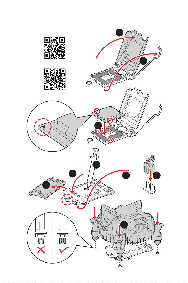
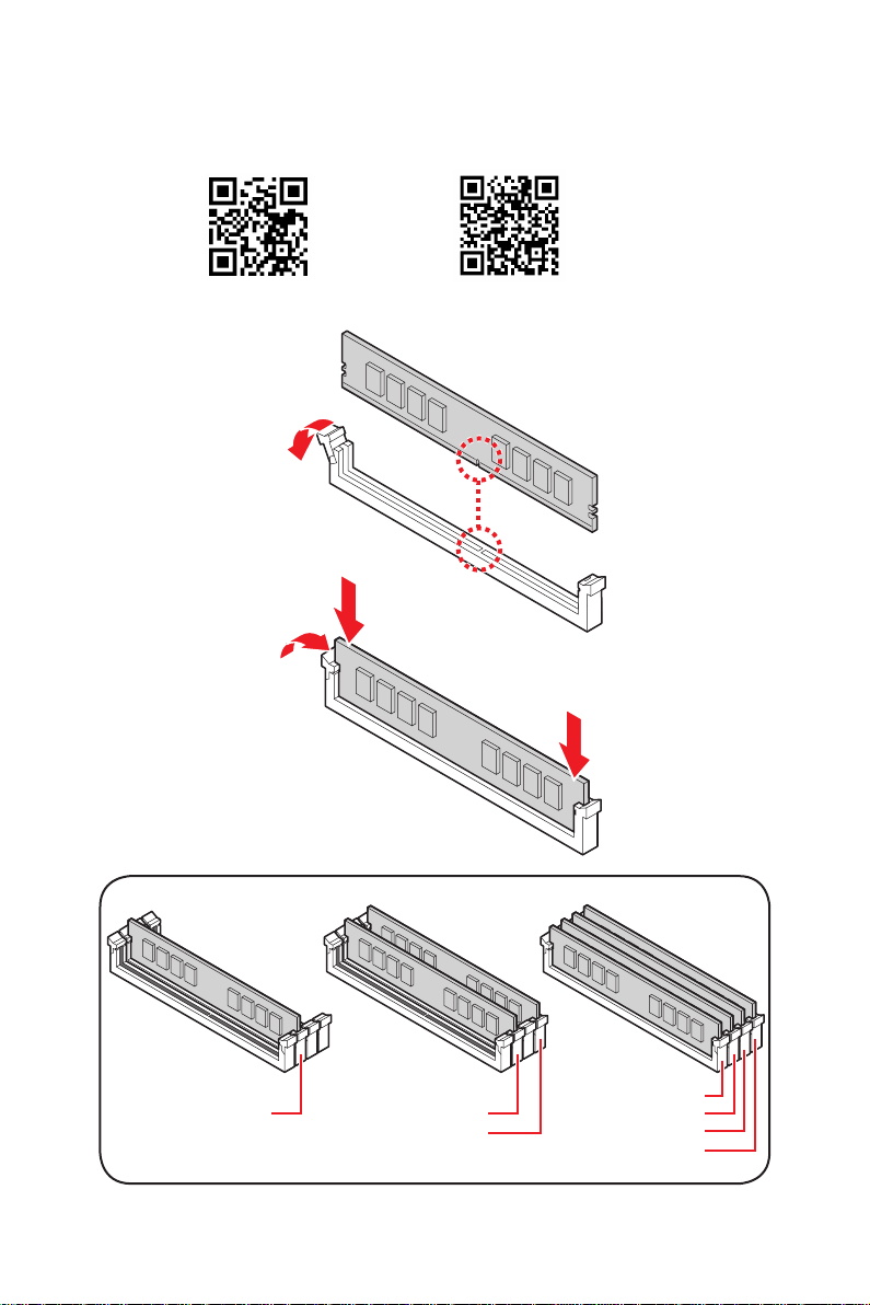
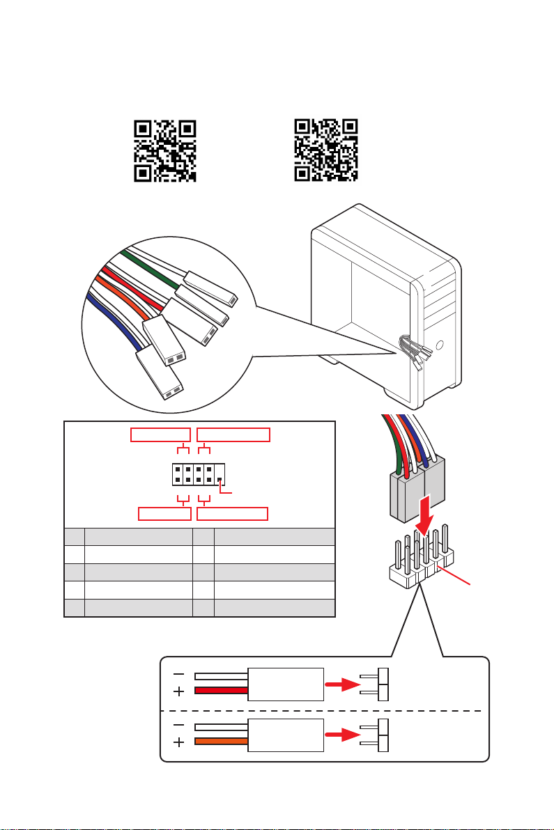
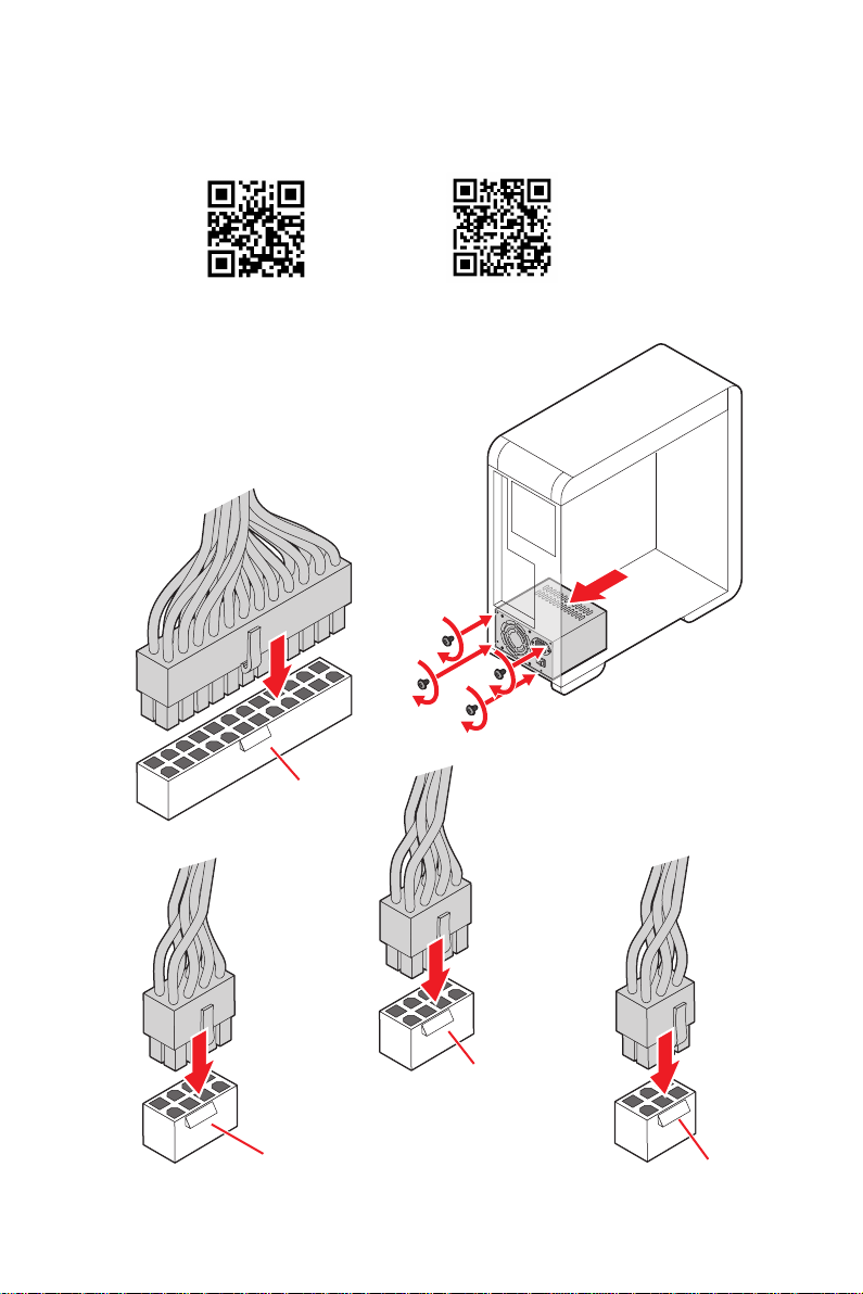
MSI MEG Z590 GODLIKE User manual

1
Quick Start
Quick Start
Thank you for purchasing the MSI® MEG Z590 GODLIKE
motherboard. This Quick Start section provides demonstration
diagrams about how to install your computer. Some of the
installations also provide video demonstrations. Please link to the
URL to watch it with the web browser on your phone or tablet. You
may have even link to the URL by scanning the QR code.
MEG Z590 GODLIKE
MSI® MEG Z590 GODLIKE
MEG Z590 GODLIKE
MEG Z590 GODLIKE

2Quick Start
1
2
3
6
45
7
8
9
Youtube
http://v.youku.com/v_show/id_
XMTg2MjMwOTE2NA==.html
https://youtu.be/Xv89nhFk1vc

3
Quick Start
http://youtu.be/T03aDrJPyQs
Youtube
http://v.youku.com/v_show/id_XNzUyMTI5ODI4.html
DIMMA2 DIMMA2
DIMMB2
DIMMA1
DIMMA2
DIMMB1
DIMMB2

4Quick Start
HDD LED
RESET SW
JFP1
HDD LED HDD LED -
HDD LED +
POWER LED -
POWER LED +
POWER LED
1
2 10
9
+
+
+-
--
-
+
Power LED
HDD LED Reset Switch
Reserved
Power Switch
JFP1
1 HDD LED + 2 Power LED +
3 HDD LED - 4 Power LED -
5 Reset Switch 6 Power Switch
7 Reset Switch 8 Power Switch
9 Reserved 10 No Pin
RESET SW
POWER SW
POWER LED+
POWER LED-
HDD LED
Connecting the Front Panel Header/
http://youtu.be/DPELIdVNZUI
Youtube
http://v.youku.com/v_show/id_XNjcyMTczMzM2.html

5
Quick Start
https://youtu.be/wWI6Qt51Wnc
https://v.youku.com/v_show/id_
XNDUwMDUyNTkwOA==.html
Youtube
8 8
1
2
Torque:
3 kgf·cm*
*3 kgf·cm
= 0.3 N·m
= 2.6 lbf·in

6Quick Start
ATX_PWR1
http://youtu.be/gkDYyR_83I4 http://v.youku.com/v_show/id_XNDkzODU0MDQw.html
Youtube

7
Quick Start
http://youtu.be/RZsMpqxythc
http://v.youku.com/v_show/
id_XNDkzODU5MTky.html
Youtube
1
23
4
5

8Quick Start
http://youtu.be/mG0GZpr9w_A
http://v.youku.com/v_show/
id_XNDkyOTc3MzQ4.html
Youtube
1
2
3
4
5
6

9
Quick Start
or
M3

10 Quick Start

11
Quick Start
4
3
12

12 Quick Start
NOTE

1
Contents
Contents
Safety Information................................................................................................. 3
..................................................................................... 4
Specifications......................................................................................................... 5
.................................................................... 13
Package contents ................................................................................................ 14
Rear I/O Panel ..................................................................................................... 15
LAN Port LED Status Table .................................................................................. 15
.................................................................................... 15
......................................................................................... 16
Installing Antennas............................................................................................... 18
................................................ 19
Overview of Components .................................................................................... 20
........................................................................................................... 21
DIMM Slots............................................................................................................ 22
.......................................................................... 23
................................................................................... 25
Installing M.2 XPANDER-Z Gen4 S card .............................................................. 28
....................................................................... 31
................................................................... 32
............................................................................ 32
............................. 33
JSLOW1: Slow Mode Booting Jumper.................................................................. 34
....................................................... 34
............................................................ 34
.............................................................................................. 35
............................................................. 35
............................................................ 36
.................................................................... 36
............................................................................. 37
........................................................................... 37
................................................................ 38
.................................. 40
....................................................................... 41
POWER1, RESET1: Power Button, Reset Button ................................................. 41
........................................................... 42
BIOS_SW1: Multi-BIOS Switch ............................................................................. 42

2Contents
JRGB1: RGB LED connector................................................................................. 43
............................................ 44
........................................................................ 45
..................................................................................... 46
................................................................ 46
Onboard LEDs...................................................................................................... 47
EZ Debug LED....................................................................................................... 47
XMP LED .............................................................................................................. 47
JPWRLED1: LED power input............................................................................... 47
................................................................................................... 48
................................................................................... 49
................................................................................................... 49
.............................................................................. 49
Boot Phases.......................................................................................................... 49
......................................................................................... 50
................................................................................................ 54
............................... 54
Installing OS, Drivers & MSI Center.................................................................... 55
Installing Windows® 10......................................................................................... 55
Installing Drivers .................................................................................................. 55
............................................................................................................ 55
UEFI BIOS............................................................................................................. 56
BIOS Setup............................................................................................................ 57
Entering BIOS Setup............................................................................................. 57
BIOS User Guide ................................................................................................... 57
Resetting BIOS...................................................................................................... 58
Updating BIOS....................................................................................................... 58

3
Safety Information
Safety Information
The components included in this package are prone to damage from electrostatic
computer assembly.
Ensure that all components are securely connected. Loose connections may cause
the computer to not recognize a component or fail to start.
Hold the motherboard by the edges to avoid touching sensitive components.
handling the motherboard to prevent electrostatic damage. If an ESD wrist strap is
not available, discharge yourself of static electricity by touching another metal object
before handling the motherboard.
Store the motherboard in an electrostatic shielding container or on an anti-static
pad whenever the motherboard is not installed.
Before turning on the computer, ensure that there are no loose screws or metal
components on the motherboard or anywhere within the computer case.
Do not boot the computer before installation is completed. This could cause
permanent damage to the components as well as injury to the user.
If you need help during any installation step, please consult a certified computer
technician.
Always turn off the power supply and unplug the power cord from the power outlet
before installing or removing any computer component.
Make sure that your electrical outlet provides the same voltage as is indicated on
the PSU, before connecting the PSU to the electrical outlet.
Place the power cord such a way that people can not step on it. Do not place
anything over the power cord.
All cautions and warnings on the motherboard should be noted.
If any of the following situations arises, get the motherboard checked by service
personnel:
Liquid has penetrated into the computer.
The motherboard has been exposed to moisture.
The motherboard does not work well or you can not get it work according to user
guide.
The motherboard has been dropped and damaged.
The motherboard has obvious sign of breakage.
the motherboard.

4Contents
Case stand-off notification
Before installing the motherboard into the case, install first the necessary mounting
stand-off required for a motherboard on the mounting plate in the case.
To prevent damage to the motherboard, any unnecessary mounting stand-off between
the motherboard circuits and the computer case is prohibited
serve as a warning to user.

5
Specifications
Specifications
CPU
Processors*
Processor socket LGA1200
* Please go to intel.com for compatibility information
Chipset
Memory
4x DDR4 memory slots, support up to 128GB*
Supports 1R 2133/ 2666/ 2933 MHz for 10th Gen Intel®
Supports 1R 2133/ 2666/ 2933/ 3200 MHz for 11th Gen
Max. overclocking frequency:
* Please refer www.msi.com for more information on compatible memory.
Expansion Slot
Multi-GPU

6Specifications
Thunderbolt 4
I
Support up to 40 Gbps transfer rate with Thunderbolt
devices
Support up to 20 Gbps transfer rate with USB4 devices
Support up to 10Gbps transfer rate with USB 3.2
devices
Support up to 5V/3A , 15W power charging
Each port can daisy-chain up to three Thunderbolt 4
devices or five Thunderbolt 3 devices
DisplayPort of the motherboard or discrete graphics card
Storage
Supports 2242/ 2260/ 2280/ 22110 storage devices
2242/ 2260/ 2280 storage devices
2242/ 2260/ 2280/ 22110 storage devices
storage devices***
Supports Intel® Smart Response Technology for Intel
* SATA2 will be unavailable when installing M.2 SATA SSD in the M2_2 slot.
updated the drivers and BIOS to the latest version from MSI website.

7
Specifications
RAID
Supports RAID 0, RAID 1, RAID 5 and RAID 10 for SATA
storage devices
Supports RAID 0, RAID 1 and RAID 5 for M.2 NVMe storage
devices
USB
2x USB 2.0 ports are available through the internal
USB 2.0 connector
Hub GL850G
2x USB 2.0 ports are available through the internal
USB 2.0 connector
back panel, 4 ports are available through the internal
Audio
Supports S/PDIF output
LAN
1x Intel® I225-V 2.5Gbps LAN controller
Wireless LAN &
Bluetooth®
Intel® WiFi-6E AX210
slot
Supports MU-MIMO TX/RX, 2.4GHz/ 5GHz/ 6GHz*
Supports 802.11a/ b/ g/ n/ ac/ ax
Supports Bluetooth® 5.2**, FIPS, FISMA
* Wi-Fi 6E 6GHz may depend on every country’s regulations and will be ready in
WIN10 21H1.
** Bluetooth 5.2 will be ready in WIN10 21H1.

8Specifications
Back Panel
Connector
1x Flash BIOS button
6x USB 3.2 Gen 1 5Gbps Type-A ports
2x USB 3.2 Gen 2 10Gbps Type-A ports
2x Wi-Fi Antenna connectors
1x Optical S/PDIF Out connector
Internal Connector
1x 24-pin ATX main power connector
2x 8-pin ATX 12V power connectors
6x SATA 6Gb/s connectors
1x 4-pin water-pump fan connector
8x 4-pin system fan connectors
1x Front panel audio connector
2x System panel connectors
2x 2-pin Thermal sensors connectors
1x TPM module connector
1x Tuning controller connector
1x 3-pin Water flow meter connector
Jumper
1x Slow mode jumper
2x Low Temperature Booting jumpers
Table of contents
Languages:
Other MSI Motherboard manuals

MSI
MSI MS-6382 User manual

MSI
MSI MEG Z490 UNIFY User manual

MSI
MSI Z370 GAMING PLUS User manual

MSI
MSI MAG Series User manual

MSI
MSI H310-A PRO User manual

MSI
MSI MPG Z590 GAMING CARBON WIFI User manual

MSI
MSI MAG Z390 TOMAHAWK User manual

MSI
MSI K9NGM Series User manual

MSI
MSI MEG Z390 GODLIKE User manual

MSI
MSI Z97S SLI PLUS User manual