MSI MPG X570S Carbon EK X User manual

I
MPG X570S CARBON MAX WIFI
Motherboard
User Guide
Benutzerhandbuch
Manuel d’utilisation
Руководство пользователя
取扱説明書
사용 명서
使用手冊
使用手册

III
Quick Start
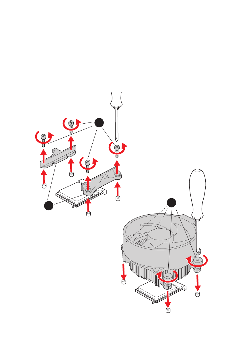
Thank you for purchasing the MSI® motherboard. This Quick Start section provides
demonstration diagrams about how to install your computer. Some of the installations
also provide video demonstrations. Please link to the URL to watch it with the web
browser on your phone or tablet. You may have even link to the URL by scanning the
QR code.
Kurzanleitung
Danke, dass Sie das MSI® Motherboard gewählt haben. Dieser Abschnitt der
Kurzanleitung bietet eine Demo zur Installation Ihres Computers. Manche
Installationen bieten auch die Videodemonstrationen. Klicken Sie auf die URL, um
diese Videoanleitung mit Ihrem Browser auf Ihrem Handy oder Table anzusehen. Oder
scannen Sie auch den QR Code mit Ihrem Handy, um die URL zu öffnen.
Présentation rapide
Merci d’avoir choisi la carte mère MSI®. Ce manuel fournit une rapide présentation
avec des illustrations explicatives qui vous aideront à assembler votre ordinateur.
Des tutoriels vidéo sont disponibles pour certaines étapes. Cliquez sur le lien fourni
pour regarder la vidéo sur votre téléphone ou votre tablette. Vous pouvez également
accéder au lien en scannant le QR code qui lui est associé.
Благодарим вас за покупку материнской платы MSI®. В этом разделе представлена
информация, которая поможет вам при сборке комьютера. Для некоторых этапов
сборки имеются видеоинструкции. Для просмотра видео, необходимо открыть
соответствующую ссылку в веб-браузере на вашем телефоне или планшете. Вы
также можете выполнить переход по ссылке, путем сканирования QR-кода.
この度は MSI® マザーボードをお買い上げいただき、誠にありがとうございます。このクイッ
クスタートにはPCの組み立て方法のデモンストレーション図を掲載しています。いくつかの
組み立て手順に付きましては、実演ビデオを提供しています。スマートフォンやタブレット端
末のウェブブラウザで本書に記載されたURLにアクセスしてご覧ください。QRコードをスキ
ャンすることでもURLのリンク先をご参照頂けます。
MSI® 메인보드를 선택해주셔서 감사합니다. 이 부분에서는 컴퓨터를 설치하는 방법에 대한
데모 다이어그램과 일부 데모 동영상을 제공하고 있습니다. 휴대전화 또는 태블릿의 웹
브라우저를 통하여 URL에 링크한 후 설치 동영상을 감상하시기 바랍니다. 또는 QR 코드를
스캔하여 URL에 링크할 수도 있습니다.
感謝您購買 MSI® 主機板。本快速指引章節提供您安裝電腦的示範圖解,亦提供部分組件
的安裝示範影片;請您以智慧型手機或平板的瀏覽器連上 URL 網址進行觀看。您也可以
掃描 QR code 的方式快速連接至網址。
感谢您购买 MSI® 主板。本快速入门部分提供了有关如何安装计算机演示图。某些设施还
提供了视频演示。请使用您的手机或平板电脑上的网页浏览器链接至网址观看。您也可以
通过扫描QR码链接到URL。

IV
Installing a Processor/ Installation des Prozessors/ Installer un
1
2
3
6
4
5
7
8
9
Youtube
http://v.youku.com/v_show/id_
XMTg2MjMwOTE2NA==.html
https://youtu.be/Xv89nhFk1vc
CPU_FAN1

V
Important
If you are installing the screw-type CPU heatsink, please follow the figure below to
remove the retention module first and then install the heatsink.
スクリュータイプのCPUクーラーを取り付ける場合は、下記の図のように、まずリテンション
モジュールを外してからCPUクーラーを取り付けて下さい。
나사타입의 CPU 히트싱크를 장착 할 경우, 아래 그림과 같이 쿨러 지지대를 제거 후
히트싱크를 장착 하십시오.
如果要安裝螺絲式的CPU散熱器,請遵照下圖步驟先移除固定模組,再安裝散熱器。
如果要安装螺丝式CPU散热器,请按照如下图步骤先移除固定模块,然后再安装散热器。
1
23

VII
Connecting the Front Panel Header/ Anschließen der
Frontpanel-Stiftleiste/ Connecter un connecteur du panneau
HDD LED
RESET SW
JFP1
HDD LED HDD LED -
HDD LED +
POWER LED -
POWER LED +
POWER LED
1
2 10
9
+
+
+---
-
+
Power LED
HDD LED Reset Switch
Reserved
Power Switch
JFP1
1 HDD LED + 2 Power LED +
3HDD LED - 4Power LED -
5 Reset Switch 6 Power Switch
7 Reset Switch 8 Power Switch
9 Reserved 10 No Pin
RESET SW
POWER SW
POWER LED+
POWER LED-
HDD LED
http://youtu.be/DPELIdVNZUI
Youtube
http://v.youku.com/v_show/id_XNjcyMTczMzM2.html

XII
Connecting Peripheral Devices/ Peripheriegeräte/ Connecter
Processor with integrated graphics

XIII
4
3
12

1
Contents
Contents
Safety Information................................................................................................. 3
Case stand-off notification ..................................................................................... 4
Avoid collision notification...................................................................................... 4
Specifications......................................................................................................... 5
Package contents ................................................................................................ 13
Rear I/O Panel ..................................................................................................... 14
LAN Port LED Status Table .................................................................................. 14
Audio Ports Configuration.................................................................................... 14
Realtek Audio Console ......................................................................................... 15
Installing Antennas............................................................................................... 17
Overview of Components .................................................................................... 18
CPU Socket ........................................................................................................... 19
DIMM Slots............................................................................................................ 20
PCI_E1~4: PCIe Expansion Slots.......................................................................... 21
M2_1~4: M.2 Slots (Key M) ................................................................................... 22
SATA1~8: SATA 6Gb/s Connectors....................................................................... 24
JFP1, JFP2: Front Panel Connectors................................................................... 24
CPU_PWR1~2, ATX_PWR1: Power Connectors................................................... 25
CPU_FAN1, PUMP_FAN1, SYS_FAN1~6: Fan Connectors.................................. 26
JUSB4~5: USB 2.0 Connectors............................................................................. 27
JUSB2~3: USB 3.2 Gen 1 5Gbps Connectors ....................................................... 27
JUSB1: USB 3.2 Gen 2 10Gbps Type-C Connector............................................... 28
JAUD1: Front Audio Connector ............................................................................ 28
JCI1: Chassis Intrusion Connector....................................................................... 29
T_SEN1: Thermal Sensor Connectors................................................................. 29
JDASH1 : Tuning Controller connector................................................................ 30
JBAT1: Clear CMOS (Reset BIOS) Jumper........................................................... 30
JRGB1: RGB LED connectors............................................................................... 31
JRAINBOW1~2: Addressable RGB LED connectors ............................................ 32
JCORSAIR1: CORSAIR Connector ........................................................................ 33
English

2Contents
Onboard LEDs...................................................................................................... 34
EZ Debug LED....................................................................................................... 34
JPWRLED1: LED power input............................................................................... 34
LED_SW1: EZ LED Control................................................................................... 34
Debug Code LED................................................................................................... 35
Hexadecimal Character Table.............................................................................. 35
Boot Phases.......................................................................................................... 35
Debug Code LED Table......................................................................................... 35
Installing OS, Drivers & MSI Center.................................................................... 40
Installing Windows® 10......................................................................................... 40
Installing Drivers .................................................................................................. 40
MSI Center............................................................................................................ 40
............................................................................................................. 41
BIOS Setup........................................................................................................... 42
Entering BIOS Setup............................................................................................. 42
BIOS User Guide ................................................................................................... 42
Resetting BIOS...................................................................................................... 43
Updating BIOS....................................................................................................... 43

3
Safety Information
Safety Information
The components included in this package are prone to damage from electrostatic
discharge (ESD). Please adhere to the following instructions to ensure successful
computer assembly.
Ensure that all components are securely connected. Loose connections may cause
the computer to not recognize a component or fail to start.
Hold the motherboard by the edges to avoid touching sensitive components.
It is recommended to wear an electrostatic discharge (ESD) wrist strap when
handling the motherboard to prevent electrostatic damage. If an ESD wrist strap is
not available, discharge yourself of static electricity by touching another metal object
before handling the motherboard.
Store the motherboard in an electrostatic shielding container or on an anti-static
pad whenever the motherboard is not installed.
Before turning on the computer, ensure that there are no loose screws or metal
components on the motherboard or anywhere within the computer case.
Do not boot the computer before installation is completed. This could cause
permanent damage to the components as well as injury to the user.
If you need help during any installation step, please consult a certified computer
technician.
Always turn off the power supply and unplug the power cord from the power outlet
before installing or removing any computer component.
Keep this user guide for future reference.
Keep this motherboard away from humidity.
Make sure that your electrical outlet provides the same voltage as is indicated on
the PSU, before connecting the PSU to the electrical outlet.
Place the power cord such a way that people can not step on it. Do not place
anything over the power cord.
All cautions and warnings on the motherboard should be noted.
If any of the following situations arises, get the motherboard checked by service
personnel:
Liquid has penetrated into the computer.
The motherboard has been exposed to moisture.
The motherboard does not work well or you can not get it work according to user
guide.
The motherboard has been dropped and damaged.
The motherboard has obvious sign of breakage.
Do not leave this motherboard in an environment above 60°C (140°F), it may damage
the motherboard.

4Contents
Case stand-off notification
To prevent damage to the motherboard, any unnecessary mounting stand-off between
the motherboard circuits and the computer case is prohibited. The Case standoff keep
out zone signs will be marked on the backside of motherboard (as shown below) to
serve as a warning to user.
Avoid collision notification
Protective paint is printed around each screw hole to prevent parts from being
scratched.

5
Specifications
Specifications
Supports AMD Ryzen™ 5000 Series, 5000 G-Series, 4000
G-Series, 3000 Series, 3000 G-Series, 2000 Series and 2000
G-Series desktop processors*
Supports Socket AM4
* Please go to msi.com to get the newest support status as new processors are
released.
Chipset AMD X570 Chipset
Memory
4x DDR4 memory slots, support up to 128GB
Supports 1866/ 2133/ 2400/ 2667/ 2800/ 2933/ 3000/ 3066/
3200 MHz by JEDEC*
Max overclocking frequency by A-XMP OC mode:
For Ryzen™ 5000 G-Series & 4000 G-Series
processors
1DPC 1R Max speed up to 5300 MHz
1DPC 2R Max speed up to 4266 MHz
2DPC 1R Max speed up to 4400 MHz
2DPC 2R Max speed up to 3600 MHz
For Ryzen™ 5000 Series & 3000 Series processors
1DPC 1R Max speed up to 5100 MHz
1DPC 2R Max speed up to 4000 MHz
2DPC 1R Max speed up to 4000 MHz
2DPC 2R Max speed up to 3600 MHz
Supports Dual-Channel mode
Supports non-ECC, un-buffered memory
*Please refer to msi.com for more information on compatible memory.
Continued on next page

6Specifications
Continued from previous page
Expansion Slot
Supports PCIe 4.0 / PCIe 3.0
PCIe 4.0 is available only on AMD Ryzen™ 5000 Series
and 3000 Series desktop processors
1x PCIe x16 slot (From processor)
PCI_E1 supports PCIe 4.0/ 3.0 x16
PCI_E1 supports PCIe 3.0 x8 on AMD Ryzen™ 3000 G-
and 2000 G- series desktop processors
1x PCIe x16 slot (From X570 chipset)
PCI_E4* supports PCIe 4.0/ 3.0 x4
2x PCIe 3.0 x1 slots (From X570 chipset)
* The PCI_E4 slot will be unavailable, when installing M.2 SSD into the M2_4
slot.
Onboard Graphics
1x HDMI 2.1 port, supports a maximum resolution of 4K
60Hz*/**
* Available only on processors featuring integrated graphics.
** Graphics specifications may vary depending on the CPU installed.
Supports AMD CrossFire™ Technology
LAN 1x Realtek® 8125B 2.5Gbps LAN Controller
Wireless LAN &
Bluetooth®
Intel® Wi-Fi 6E AX210
The Wireless module is pre-installed in the M.2 (Key-E)
slot
Supports MU-MIMO TX/RX, 2.4GHz/ 5GHz/ 6GHz*
(160MHz) up to 2.4Gbps
Supports 802.11 a/ b/ g/ n/ ac/ ax
Supports Bluetooth® 5.2**, FIPS, FISMA
* Wi-Fi 6E 6GHz may depend on every country’s regulations and will be ready in
WIN10 21H1.
** Bluetooth 5.2 will be ready in WIN10 21H1.
Continued on next page

7
Specifications
Continued from previous page
Storage
8x SATA 6Gb/s ports (from AMD X570 Chipset)
4x M.2 slots (Key M)
Support PCIe 4.0 / PCIe 3.0
PCIe 4.0 is available only on AMD Ryzen™ 5000 Series
and 3000 Series desktop processors
M2_1 slot (from Processor)
Supports 2242/ 2260/2280/22110 storage devices
Supports up to SATA 6Gb/s
M2_2, M2_3* and M2_4 slots (from AMD X570 Chipset)
M2_2 & M2_4 slots support 2242/ 2260/ 2280
storage devices
M2_3 slot supports 2242/ 2260/2280/22110 storage
devices
M2_2 & M2_3 slots support up to SATA 6Gb/s
* SATA5-6 will be unavailable when installing SATA SSD in the M2_3 slot;
SATA5-8 will be unavailable when installing PCIe SSD in the M2_3 slot.
RAID Supports RAID 0, RAID 1 and RAID 10
Audio
Realtek® ALC4080 Codec
7.1-Channel High Definition Audio
Supports S/PDIF output
I/O Controller NUVOTON NCT6687D-R Controller Chip
Hardware Monitor
CPU/ System/ Chipset temperature detection
CPU/ System/ Pump fan speed detection
CPU/ System/ Pump fan speed control
Continued on next page
Other manuals for MPG X570S Carbon EK X
3
Table of contents
Other MSI Motherboard manuals

MSI
MSI B75A-G43 seres User manual

MSI
MSI MS-7314 User manual

MSI
MSI ATX BX10 User manual

MSI
MSI X299 PRO User manual

MSI
MSI MS-6390 User manual

MSI
MSI MS-7238 User manual

MSI
MSI Z370I GAMING PRO CARBON AC User manual

MSI
MSI MPG Z690 EDGE WIFI DDR4 User manual

MSI
MSI MS-6566E User manual

MSI
MSI 661FM3-V Series User manual