MSI MS-6552 User manual

i
Version1.0
G52-MA00485
MS-6552 (v1.X)M-ATXMainboard
MSI

ii iii
ManualRev:1.0
ReleaseDate:Nov.2001
FCC-BRadioFrequencyInterferenceStatement
Thisequipmenthas beentestedand found tocomplywiththelimitsforaclass
Bdigitaldevice,pursuanttopart15oftheFCCrules.These limitsaredesigned
toprovidereasonableprotection againstharmfulinterference whentheequip-
mentisoperatedinacommercialenvironment.Thisequipmentgenerates,uses
and canradiateradiofrequencyenergyand,ifnotinstalledandusedinaccor-
dance withtheinstruction manual, maycause harmfulinterference toradio
communications.Operation ofthisequipmentinaresidentialarea islikelyto
cause harmfulinterference,inwhichcase theuserwill berequiredtocorrect
theinterference athisownexpense.
Notice1
Thechanges ormodificationsnotexpresslyapprovedby thepartyrespon-
sibleforcompliancecouldvoidtheuser’sauthoritytooperatetheequipment.
Notice2
Shieldedinterfacecables and A.C.powercord,ifany,mustbeusedinorderto
complywiththeemission limits.
VOIRLANOTICED’INSTALLATION AVANTDERACCORDERAU
RESEAU.
Edition
Nov.2001
CopyrightNotice
ThematerialinthisdocumentistheintellectualpropertyofMICRO-STAR
INTERNATIONAL.Wetake everycareinthepreparation ofthisdocument,
butno guarantee isgivenas tothecorrectness ofitscontents.Ourproducts
areundercontinualimprovementand wereservetherighttomake changes
withoutnotice.
Trademarks
All trademarks usedinthismanualarethepropertyoftheirrespectiveowners.
Inteland Pentiumareregisteredtrademarks ofIntelCorporation.
PS/2and OS/2areregisteredtrademarks ofIBMCorporation.
Windows95/98/2000 and WindowsNTareregisteredtrademarks ofMicrosoft.
NetwareisaregisteredtrademarkofNovell.
AwardisaregisteredtrademarkofAwardSoftwareInc.
RevisionHistory
Revision RevisionHistoryDate
V1.0Firstrelease Nov.2001
Micro-StarInternationalMS-6552
Testedtocomply
withFCCStandard
ForHomeorOfficeUse

iv v
1.Readthesafetyinstructionscarefully.
2.SavethisUser’sGuideforpossibleuse later.
3.Keepthisequipmentawayfromhumidity.
4.Laythisequipmenton astableand flatsurface beforesetting itup.
5.Theopeningson theenclosureareusedforairconvection and toprevent
theequipmentfromoverheating.Note:Donotcovertheopenings.
6.Make surethatthepowervoltageiswithinitssafetyrangeand has been
adjustedproperlytothevalueof110/220Vbeforeconnecting theequip-
menttothepowerinlet.
7.Placethepowercordinawaythatpeopleareunlikelytostepon it.Donot
place anything on thepowercord.
8.Alwaysunplug thepowercordbeforeinserting any add-on cardormodule.
9.All cautionsand warningson theequipmentshouldbenoted.
10.Neverpouranyliquidintotheopening thatcoulddamagetheequipment
orcause anelectricalshock.
11.If any ofthefollowing situationsarises,gettheequipmentcheckedby a
service personnel:
?thepowercordorplug isdamaged
?liquidhas penetratedintotheequipment
?theequipmenthas beenexposedtomoisture
?theequipmenthas notworkwell oryou cannotgetitworkaccording
toUser’sGuide
?theequipmentwas droppedand damaged
?theequipmenthas obvioussignsofbreakage
12.Donotleavetheisequipmentinanunconditionedenvironmentwitha
storagetemperatureof600C(1400F)orabove,whichmaydamagethe
equipment.
Safety Instructions
CAUTION:Topreventexplosion causedby improperbattery
replacement,use thesameorequivalenttypeofbatteryrecommended
by themanufactureronly.
CONTENTS
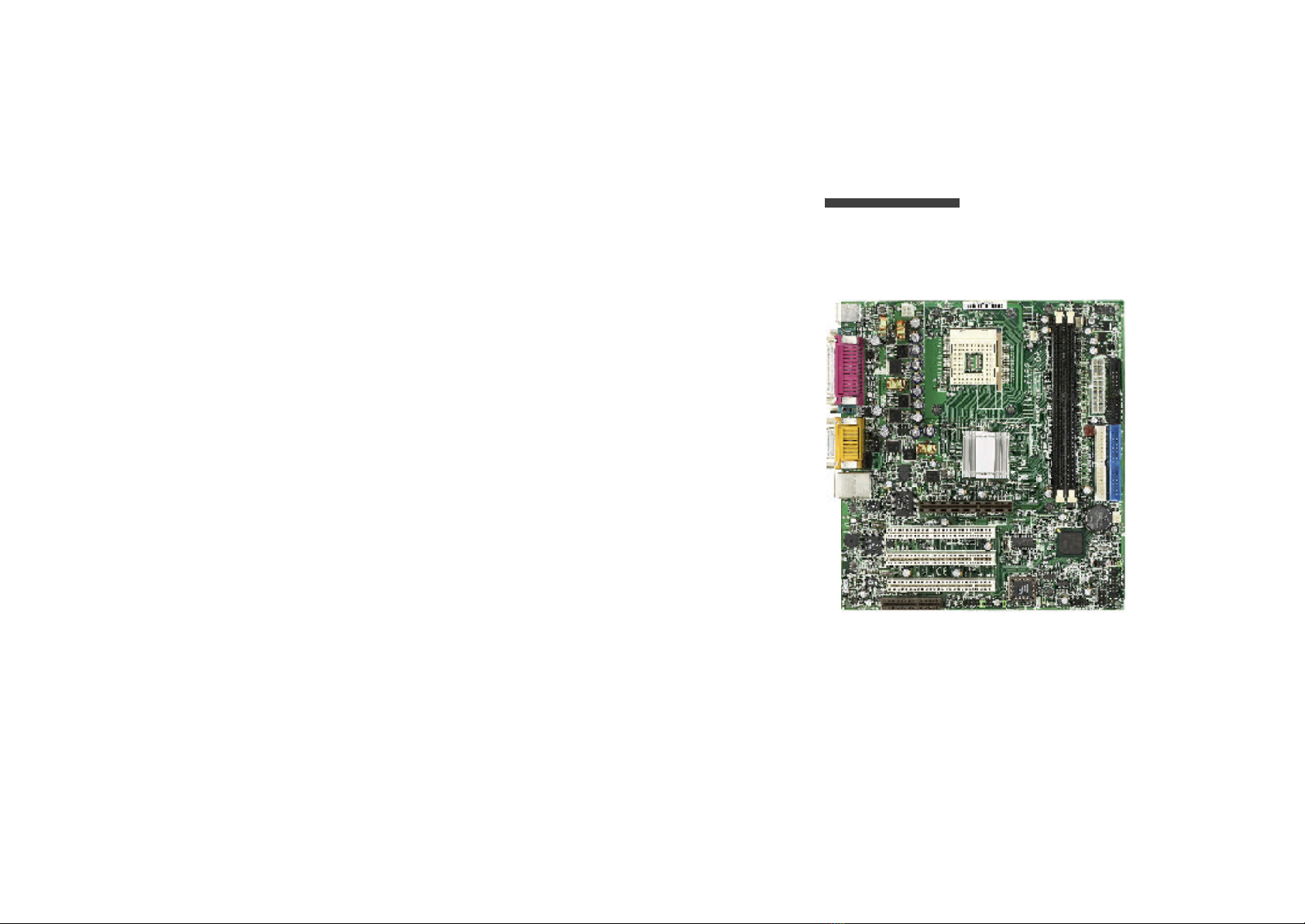
Chapter1.Introduction..................................................................................... 1-1
MainboardSpecification ..............................................................................1-2
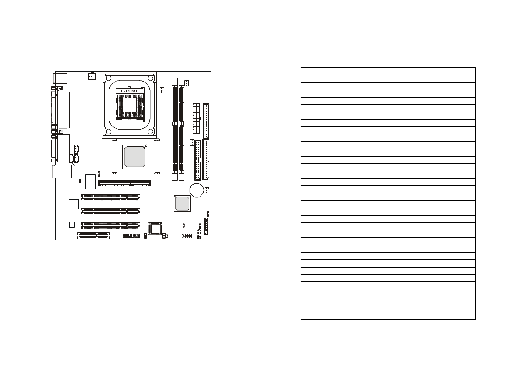
MainboardLayout........................................................................................1-4
Quick ComponentsGuide............................................................................1-5
Chapter2.HardwareSetup.............................................................................. 2-1
CentralProcessing Unit:CPU......................................................................2-2
CPUInstallation Procedures ................................................................2-2
CPUCoreSpeedDerivation Procedure..............................................2-4
MemoryInstallation ......................................................................................2-5
DDRModuleInstallation Procedures ................................................2-6
PowerSupply.................................................................................................2-7
ATX20-PinPowerConnector:ATX1.................................................2-7
ATX12VPowerConnector:JPW1......................................................2-7
BackPanel ......................................................................................................2-8
Mouse Connector:KBMS1..................................................................2-8
KeyboardConnector:KBMS1.............................................................2-9
SerialPort Connector:COM1&COM2............................................2-9
AudioPort Connectors.......................................................................2-10
Joystick/MidiConnectors..................................................................2-10
ParallelPort Connector:LPT1............................................................2-11
LANJack...............................................................................................2-12
USBConnectors..................................................................................2-12
Connectors...................................................................................................2-13
Floppy Disk DriveConnector:FDD1................................................2-13
IrDAInfraredModuleConnector:IR1.............................................2-13
HardDisk Connectors:IDE1&IDE2................................................2-14
CD-InConnector:CDIN1....................................................................2-15

vi vii
AuxLine-InConnector:CDIN2.........................................................2-15
Modem-InConnector:MDM_IN1....................................................2-15
FanPowerConnectors:PWR_FAN/SYS_FAN/CPUFAN1..........2-16
Wake OnRing Connector:JMDM1..................................................2-17
Wake OnLANConnector:WOL1....................................................2-17
Case Connector:PANEL1..................................................................2-18
FrontPanelAudioConnector:F_AUDIO.......................................2-19
USBFrontPanelConnector:USB2...................................................2-20
PowerSwitchConnector:PWR_SW1..............................................2-21
PowerSaving SwitchConnector:JGS1............................................2-21
PowerSaving LEDConnector:JGLED1...........................................2-22
ChassisIntrusion SwitchConnector:J8..........................................2-23
Jumpers.........................................................................................................2-24
ClearCMOSJumper:CLR_CMOS....................................................2-24
BIOSFlashJumper:BIOS_WP..........................................................2-25
LANEnable/DisableJumper:JLAN1...............................................2-25
OnboardAudioCodec Jumper:JP3..................................................2-26
Slots..............................................................................................................2-27
AGP(AcceleratedGraphics Port) Slot.............................................2-27
PCISlots...............................................................................................2-27
CNRSlot...............................................................................................2-27
Chapter3.AWARD® BIOSSetup .................................................................. 3-1
Entering Setup ...............................................................................................3-2
TheMainMenu ............................................................................................3-4
StandardCMOSFeatures ............................................................................3-6
AdvancedBIOSFeatures ............................................................................3-8
AdvancedChipsetFeatures ......................................................................3-11
IntegratedPeripherals................................................................................3-14
PowerManagementSetup .........................................................................3-19
PNP/PCIConfigurations.............................................................................3-24
PCHealthStatus..........................................................................................3-26
Frequency/VoltageControl ........................................................................3-27
LoadFail-Safe/OptimizedDefaults...........................................................3-28
SetSupervisor/UserPassword..................................................................3-29
Glossary................................................................................................................G-1

Getting Started
1-1
Chapter 1. Getting Started
TOPICS
MainboardSpecification 1-2
MainboardLayout1-4
QuickComponentsGuide1-5
1
Getting Started
Thankyou foryourpurchase oftheMS-6552M-ATXmainboard.Powered
by theIntel®Brookdaleand ICH2chipsets,theMS-6552mainboardisdesigned
tofittheadvancedIntel®Pentium®4processorsinthe478 pinpackage,and
providethemostefficientand professionaldesktop platformsolution tomeet
yourneeds.

Getting Started
1-3
Chapter 1
1-2
CPU
Supportssinglesocket478 forIntel®Pentium®4“Northwood”processor
Supportsup tocoreclock speedof2GHzand 2.2GHz
Chipset
Intel®Brookdalechipset
-SupportsDDRSDRAMat200/266MHzoperation (DDR200/DDR266)
-1.5VAGPinterface with4xdatatransferand 4xfastwritecapability
-8-bit,66MHz4xhub interface totheIntelICH2
Intel®ICH2chipset(360 EBGA)
-Upstreamhub interface foraccess totheIntelMCH
-2-channelUltraATA/100 BusMasterIDEcontroller
-USBcontroller1.1(expandedcapabilities for4ports)
-I/OAPIC
-SMBuscontroller
-FWHinterface
-LPCinterface
-AC’97 2.1interface
-PCI2.2interface
-Integratedsystemmanagementcontroller
MainMemory
Supportstwomemoryslots
Supportsup to2GBPC2100/PC1600 DDRSDRAMs
Supports2.5vDDRSDRAM
Slots
OneAGP(AcceleratedGraphics Port) slot
Three PCI2.232-bitMasterPCIbusslots(support3.3V/5VPCIbusinterface)
OneCNR(Communication NetworkRiser) slot
On-Board IDE
AnIDEcontrolleron theICH2chipsetprovides IDEHDD/CD-ROMwith
Mainboard SpecificationPIO,BusMasterand DMA33/100 operation modes
Canconnectup tofourIDEdevices
On-Board Peripherals
On-BoardPeripheralsinclude:
-1floppy port supports2FDDswith360K,720K,1.2M,1.44Mand
2.88Mbytes
-1PS/2mouse port,1keyboardport
-2serialports(COM1+COM2)
-1parallelport supportsSPP/EPP/ECPmode
-1IrDAconnectorforSIR/ASKIR/HPSIR
-1audio/gameport
-4USB1.1ports(Rearx2/Frontx2)
-1LANjack(Realtek 8100BLoptional)
Audio
Chipintegrated
-DirectSound AC’97 Audio
BIOS
ThemainboardBIOSprovides “Plug &Play”function whichdetectsthe
peripheraldevices and expansion cardsoftheboardautomatically.
Themainboardprovides aDesktop ManagementInterface (DMI) function
whichrecordsyourmainboardspecifications.
Dimension
M-ATXFormFactor224 mm x244 mm
Mounting
6mounting holes
Others
SupportsWOL/WOR
PC2001 compliant
Suspend toRAM/Disk
Note:TheAGPslotDOESNOTsupportthe3.3VAGPcard.Useofthe
3.3VAGPcardmaycausedamagetothemainboard.

Getting Started
1-5
Chapter 1
1-4
QuickComponentsGuideMainboard Layout
MS-6552 v1.XM-ATXMainboard
ComponentFunction Reference
ATX1ATX20-pinpowerconnectorSee p.2-7
JPW1ATX12VpowerconnectorSee p.2-7
KBMS1Mouse connectorSee p.2-8
KBMS1KeyboardconnectorSee p.2-9
COM1&COM2Serialport connectorSee p.2-9
AUDIOAudio/Joystick/MidiconnectorSee p.2-10
LPT1Parallelport connectorSee p.2-11
LANJACK(optional)Connecting toLANSee p.2-12
USBConnectorsConnecting toUSBdevices See p.2-12
FDD1Floppy disk driveconnectorSee p.2-13
IR1IrDAinfraredmoduleconnectorSee p.2-13
IDE1~IDE2Harddisk connectorsSee p.2-14
CDIN1CD-inconnectorSee p.2-15
CDIN2Auxline-inconnectorSee p.2-15
MDM_IN1Modem-inconnectorSee p.2-15
PWR_FAN/CPUFAN1/FanpowerconnectorsSee p.2-16
SYS_FAN
JMDM1Wake on ring connectorSee p.2-17
WOL1Wake on LANconnectorSee p.2-17
PANEL1Case connectorSee p.2-18
F_AUDIOFrontpanelaudioconnectorSee p.2-19
USB2FrontUSBconnectorsSee p.2-20
PWR_SW1PowerswitchconnectorSee p.2-21
JGS1Powersaving switchconnectorSee p.2-21
JGLED1Powersaving LEDconnectorSee p.2-22
J8Chassisintrusion switchconnectorSee p.2-23
CLR_CMOSClearCMOSjumperSee p.2-24
BIOS_WPBIOSflashjumperSee p.2-25
JLAN1(optional)LANenable/disablejumperSee p.2-25
JP3Onboardaudiocodec jumperSee p.2-26
AGPSlotConnecting toAGPcardsSee p.2-27
PCISlotsConnecting toexpansion cardsSee p.2-27
CNRSlotConnecting toexpansion cardsSee p.2-28
AGPSlot
BATT
+
Intel
Brookdale
chipset
ICH2
D
D
R
1
D
D
R
2
USB2
BIOS_WP
A
T
X
P
o
w
e
r
S
u
p
p
l
y
PANEL1
CLR_CMOS
JMDM1
JGLED1
JGS1
IR1
BIOS
PCI Slot 3
PCI Slot 2
PCI Slot 1
I
D
E
1
IDE2
CNR
WOL1
JP3
F_AUDIO
T:LANJack
B:USB ports
Top:ParallelPort
Bottom:
COM1
COM2
Top: mouse
Bottom:keyboard
CDIN1
J8
Codec
RTL8100BL
Winbond
83627HF-AW
JLAN1
CDIN2
MDM_IN1
JPW1 PWR_FAN
CPUFAN1
PWR_SW1
SYS_FAN
Top:
Game port
Bottom:
Line-Out
Line-In
Mic
F
D
D
1

Hardware Setup
2-1
Chapter 2. HardwareSetup
TOPICS
CentralProcessing Unit:CPU2-2
Memory2-5
PowerSupply2-7
BackPanel2-8
Connectors 2-13
Jumpers 2-24
Slots2-27
2
HardwareSetup
Thischapterprovides you withtheinformation abouthardwaresetup
procedures.Whiledoing theinstallation,becarefulinholding thecompo-
nentsand followtheinstallation procedures.Forsomecomponents,ifyou
install inthewrong orientation,thecomponentswill notworkproperly.
Use agroundedwriststrapbeforehandling computercomponents.Static
electricitymaydamagethecomponents.

Hardware Setup
2-3
Chapter 2
2-2
Installing theCPU Fan
Asprocessortechnologypushes tofasterspeedsand higherperformance,
thermalmanagementbecomes increasinglyimportant.Todissipateheat,you
needtoattachtheCPUcooling fanand heatsinkon top oftheCPU.Followthe
instructionsbelowtoinstall theHeatsink/Fan:
CentralProcessing Unit:CPU
1.Pull theleversidewaysaway
fromthesocket.Then,raise
theleverup toa90-degree
angle.
2.Lookforthedot/cutedge.The
dot/cutedgeshouldpointto-
wardstheleverpivot.The
CPUwill onlyfitinthe
correctorientation.
3.HoldtheCPUdownfirmly,
and thenclose theleverto
completetheinstallation.
CPU InstallationProcedures
Overheating willseriouslydamagetheCPUand system,
alwaysmakesurethecooling fan can workproperlyto
protecttheCPUfromoverheating.
WARNING!
ThemainboardsupportsIntel®Pentium®4processorinthe478 pin
package.Themainboarduses aCPUsocketcalledPGA478 foreasyCPU
installation.Whenyou areinstalling theCPU,makesure theCPU has a
heatsinkandacooling fanattached onthetop topreventoverheating.If
you do notfind theheatsinkand cooling fan,contactyourdealertopurchase
and install thembeforeturning on thecomputer.2. Position the heatsinkontothe reten-
tion mechanism.
1. Locatethe CPUand itsretention
mechanismon the motherboard.
3. Mountthe fan on top ofthe heatsink.
Press downthe fan until itsfourclips
getwedgedintheholes ofthe reten-
tion mechanism.
4. Press the twoleversdowntofasten
the fan.Each levercan be pressed
downinonlyONEdirection.
retention mechanism
levers
OpenLever
Dot / Cut edge
Sliding
Plate
Close
Lever

Hardware Setup
2-5
Chapter 2
2-4
Themainboardprovides 2slotsfor184-pin,2.5VDDRDIMM with4
memorybanks.You caninstall PC1600/PC2100DDRSDRAMmodules on
theDDRDIMMslots(DDR1~2).Tooperateproperly,atleastoneDIMM
modulemustbeinstalled.
Memory
IntroductiontoDDR SDRAM
DDR(DoubleDataRate)SDRAMissimilartoconventionalSDRAM,
butdoubles therateby transferring datatwice percycle.It uses 2.5voltsas
opposedto3.3voltsusedinSDRSDRAM,and requires 184-pinDIMMmod-
ules ratherthan168-pinDIMMmodules usedby SDRSDRAM.Twotypes of
DDRareavailableatthetimeofwriting:PC1600 &PC2100.PC1600 DDR
SDRAMrunning at100MHzwill produce about1.6GB/smemorybandwidth.
PC2100 running at133MHzwill produce 2.1GB/smemorybandwidth.High
memorybandwidthmakes DDRanidealsolution forhigh performance PC,
workstationsand servers.
DDRDIMM Slots
(DDR1~2)
CPU Core Speed DerivationProcedure
If CPUClock =100MHz
Core/Busratio = 14
thenCPUcorespeed = HostClock xCore/Busratio
=100MHzx14
=1.4GHz
Overclocking
Thismotherboardisdesignedtosupportoverclocking.
However,pleasemakesureyourcomponentsareabletotol-
eratesuchabnormalsetting,whiledoing overclocking.Any
attempttooperatebeyond productspecificationsisnot
recommended.Wedo notguarantee thedamagesorrisks
causedbyinadequateoperationorbeyondproduct
specifications.
WARNING!
5. Connect the fan power cable from the mounted fan to the 3-pin fan power connector
on the board.
fanpowercable
Note:DIMM 1~2 isseparately2-memory-bank capable.ButasIntel®
82845 chipsetsupportsonly4DDRmemorybanks,thetotalmemory
banksinstalledcannotexceedthemaximumquantityof4.Improper
memoryinstallation maycausemalfunction.

Hardware Setup
2-7
Chapter 2
2-6
Power Supply
ATX20-PinPower Connector:ATX1
Thisconnectorallowsyou toconnecttoanATXpowersupply.Tocon-
necttotheATXpowersupply,make suretheplugsofthepowersupplyis
insertedintheproperorientation and thepinsarealigned.Thenpushdown
thepowersupplyfirmlyintotheconnector.Thepowerconnectorsupports
instantpower onfunction whichmeansthatsystemwill bootup immediately
whenthepowersupplyconnectorisinsertedon theboard.
ThemainboardsupportsATXpowersupplyforthepowersystem.Be-
foreinserting thepowersupplyconnector,alwaysmake surethatall compo-
nentsareinstalledproperlytoensurethatno damagewill becaused.
ATX12VPower Connector:JPW1
This12VpowerconnectorisusedtoprovidepowertotheCPU.
DDR ModuleCombination
Toenablenormaloperation,atleastoneDIMMmoduleshouldbein-
stalledon themotherboard.You mayinstall memorymodules inthefollowing
combination:
JPW1
ATX1
1.Support 64 MB,128MB,256 MB&512 MBtechnologies forx8&x16 devices
2.Supporteddevices musthave4banks.
Installing DDR Modules
1.TheDDRDIMMmodulehas onlyonenotchon thecenter.
2.Insert theDDRmoduleverticallyintotheDDRDIMM slot.Make surethe
notchison therightorientation.
3.Theplasticclipsatsides oftheDIMMslotwill automaticallyclose.
Volt
FrontViewRearView
ATX1PinDefinition
JPW1PinDefinition

Hardware Setup
2-9
Chapter 2
2-8
Keyboard Connector:KBMS1
Themainboardprovides astandardPS/2®keyboardminiDINconnector
forattaching aPS/2®keyboard.You canplug aPS/2®keyboarddirectlyinto
thisconnector.
PS/2Keyboard(6-pinFemale)
TheBackPanelprovides thefollowing connectors:
BackPanel
Mouse Connector:KBMS1
Themainboardprovides astandardPS/2®mouse miniDINconnector
forattaching aPS/2®mouse.You canplug aPS/2®mouse directlyintothis
connector.Theconnectorlocation and pinassignmentsareas follows:
PS/2Mouse(6-pinFemale)
21
3
4
56
21
34
56
PIN SIGNAL DESCRIPTION
1Mouse DATA Mouse DATA
2NC Noconnection
3GND Ground
4VCC +5V
5Mouse ClockMouse clock
6NC Noconnection
PinDefinition
PIN SIGNAL DESCRIPTION
PinDefinition
SerialPortConnector:COM1&COM2
Themainboardofferstwo9-pinmaleDINconnectorsforserialport
COM1and COM2.Theportsare16550Ahigh speedcommunication ports
thatsend/receive16bytes FIFOs.You canattachaserialmouse orotherserial
devices directlytothem.
PIN SIGNAL DESCRIPTION
9-PinMaleDINConnectors
PinDefinition
12345
6789
Mouse
Keyboard USB
ParallelPort
COM1COM2
Midi/Joystick LAN
MICL-outL-in

Hardware Setup
2-11
Chapter 2
2-10
ParallelPortConnector:LPT1
Themainboardprovides a25-pinfemalecentronicconnectorforLPT.
Aparallelport isastandardprinterport thatsupportsEnhancedParallelPort
(EPP)and ExtendedCapabilities ParallelPort (ECP)mode.
Joystick/MidiConnectors
You canconnectajoystick orgamepadtothisconnector.
13 1
14
25
PIN SIGNAL DESCRIPTION
1STROBEStrobe
2DATA0Data0
3DATA1Data1
4DATA2Data2
5DATA3Data3
6DATA4Data4
7DATA5Data5
8DATA6Data6
9DATA7Data7
10 ACK#Acknowledge
11 BUSYBusy
12 PE PaperEnd
13 SELECTSelect
14 AUTOFEED#AutomaticFeed
15 ERR# Error
16 INIT# Initialize Printer
17 SLIN#SelectIn
18 GND Ground
19 GND Ground
20 GND Ground
21 GND Ground
22 GND Ground
23 GND Ground
24 GND Ground
25 GND Ground
PinDefinition
AudioPortConnectors
LineOutisaconnectorforSpeakersorHeadphones.LineInisused
forexternalCDplayer,Tapeplayer,orotheraudiodevices.Micisaconnec-
torformicrophones.
Note:Detailson theapplication of6-channelaudiocan beacquiredin
AppendixA.
1/8”Stereo AudioConnectors
LineOutLine InMIC

Hardware Setup
2-13
Chapter 2
2-12
Themainboardprovides connectorstoconnecttoFDD,IDEHDD,case,
modem,LAN,USBPorts,IRmoduleand CPU/SystemFAN.
Floppy DiskDriveConnector:FDD1
Themainboardprovides astandardfloppy diskdriveconnectorthatsup-
ports360K,720K,1.2M,1.44Mand 2.88Mfloppy disk types.
Connectors
IrDA Infrared ModuleHeader:IR1
Thisconnectorallowsyou toconnecttoIrDAInfraredmodules.You
mustconfigurethesetting through theBIOSsetup touse theIRfunction.The
IR2iscomplianttoIntelFrontPanelI/OConnectivityDesign Guide.
LAN Jack(optional)
Themainboardprovides onestandardRJ-45 jackforconnection to
LocalArea Network(LAN).You canconnectanetworkcabletotheLAN
jack.
LANRJ-45 Jack
PinDefinition
FDD1
IR1
IR1PinDefinition
Themainboardprovides aUHCI(UniversalHostControllerInterface)
UniversalSerialBusrootforattaching USBdevices suchas keyboard,mouse
orotherUSB-compatibledevices.You canplug theUSBdevice directlyinto
thsconnector.
USBPorts
1234
5678
PIN SIGNAL DESCRIPTION
USB PortDescription
USBConnectors

Hardware Setup
2-15
Chapter 2
2-14
Modem-InConnector:MDM-IN1
Theconnectorisformodemwithinternalaudioconnector.
CD-InConnector:CDIN1
TheconnectorisforCD-ROMaudioconnector.
AuxLine-InConnector:CDIN2
TheconnectorisforDVDadd-on cardwithLine-inconnector.
MDM-IN1
Hard DiskConnectors:IDE1 &IDE2
Themainboardhas a32-bitEnhancedPCIIDEand UltraDMA33/66/
100 controllerthatprovides PIOmode0~4,BusMaster,and UltraDMA/33/
66/100 function.You canconnectup tofourharddisk drives,CD-ROM,
120MBFloppy (reservedforfutureBIOS)and otherdevices.These connec-
torssupport theprovidedIDEharddisk cable.
IDE1 (PrimaryIDEConnector)
ThefirstharddriveshouldalwaysbeconnectedtoIDE1.IDE1can
connectaMasterand aSlavedrive.You mustconfiguresecond hard
drivetoSlavemodeby setting thejumperaccordingly.
IDE2 (SecondaryIDEConnector)
IDE2canalsoconnectaMasterand aSlavedrive.
TIP:
Ifyou install twoharddiskson cable,you mustconfigurethe
second drive toSlave modebysetting itsjumper.Refertothe
harddiskdocumentation suppliedbyharddiskvendorsforjumper
setting instructions.
I
D
E
2
I
D
E
1
Note:
Mono-OutisconnectedtotheModemspeaker-outconnector.
Phone-InisconnectedtotheModemMicrophone-Inconnector.
CDIN1/CDIN2

Hardware Setup
2-17
Chapter 2
2-16
WakeOnRing Connector:JMDM1
Thisconnectorallowsyou toconnecttoamodemcardwithWake On
Ring function.Theconnectorwill powerup thesystemwhenasignalisre-
ceivedthrough themodemcard.
FanPower Connectors:PWR_FAN/SYS_FAN/CPUFAN1
ThePWR_FAN(powersupplyfan),CPUFAN1(CPUfan)&SYS_FAN
(systemfan)support systemcooling fanwith+12V.Itsupportsthree-pinhead
connector.Whenconnecting thewiretotheconnectors,alwaystake notethat
theredwireisthepositiveand shouldbeconnectedtothe+12V,theblackwire
isGround and shouldbeconnectedtoGND.If themainboardhas aSystem
HardwareMonitorchipseton-board,you mustuse aspeciallydesignedfan
withspeedsensortotake advantageoftheCPUfancontrol.
Note:
1.Alwaysconsult thevendorforproperCPUcooling fan.
2.CPUFan supportsthefan control.Youcan install thePCAlertutility
thatwill automaticallycontroltheCPUFan speedaccordingtothe
actualCPUtemperature.
WakeOnLAN Connector:WOL1
Thisconnectorallowsyou toconnecttoaLANcardwithWake On
LANfunction.You canwake up thecomputerviaremotecontrolthrough a
localarea network.
SYS_FAN
PWR_FANCPUFAN1
WOL1
JMDM1

Hardware Setup
2-19
Chapter 2
2-18
FrontPanelAudioConnector:F_AUDIO
You canconnectanoptionalaudioconnectortotheF_AUDIOfront
panelaudioconnector.TheF_AUDIOiscomplianttoIntelFrontPanelI/O
ConnectivityDesign Guide.
Case Connector:PANEL1
Thecase connectorblock PANEL1allowsyou toconnecttothePower
Switch,ResetSwitch,Speaker,PowerLED,and HDDLEDon thecase..
F_AUDIO
Pin Description Pin Description
1Keylock10 Keylock
2NC 11 NC
3HDD_LED+ 12 HDD_LED-
4GND 13 CASE_SPK
5 PWR_LEDY14 CASE_SPK
6 PWR_LEDG15 CASE_SPK
7 PWR_SW+ 16 CASE_SPK
8 PWR_SW-17 RESET+
9NC 18 RESET-
F_AUDIOPinDefinition
Pin Description Pin Description
PANEL1

Hardware Setup
2-21
Chapter 2
2-20
Power Saving SwitchConnector:JGS1
Attachapowersaving switchtothisconnector.Pressing theswitch
once willhavethesystementerthesleep/suspend state.Pressany keytowake
upthesystem.
Power SwitchConnector:PWR_SW1
Attachapowerswitchtothisconnector.Pressing theswitchwill turn
on/offthesystem.
PWR_SW1
JGS1
FrontUSBConnectors:USB2
Depending on themodelyou havepurchased,yourmainboardcould
provideONEorTHREE USB(UniversalSerialBus)pinheadersthatallow
you toconnectoptionalUSBportsforfrontpanel.
Pin Description Pin Description
1VCC 2NC
3USB0-4GND
5USB0+ 6 USB1+
7GND 8USB1-
9GND 10 VCC
USB2PinDefinition
USB2

Hardware Setup
2-23
Chapter 2
2-22
ChassisIntrusionSwitchConnector:J8
Thisconnectorisconnectedtoa2-pinchassisswitch.If thechassisis
opened,theswitchwillbeshort.Thesystemwill recordthisstatusand show
awarning messageon thescreen.Toclearthewarning,you mustenterthe
BIOSutilityand cleartherecord.
Power Saving LEDConnector:JGLED1
JGLED1isconnectedtoapowersaving LED.Therearethree types of
LEDthatyou canuse:3-pindualcoloror2-pinsing/dualcolorLED.If con-
nectedtoadualcolorLED,theLED
JGLED1
3-PinLED2-PinLED
Green:Full-onMode DualColor
Orange:SleepMode
J8

Hardware Setup
2-25
Chapter 2
2-24
BIOSFlashJumper:BIOS_WP
Thisjumperisusedtolock orunlock thebootblock area on BIOS.
Whenunlocked,theBIOSbootblock area canbeupdated.Whenlocked,the
BIOSbootblock area cannotbeupdatedl.
LAN Enable/DisableJumpers:JLAN1(optional)
Use these jumperstoenableordisabletheonboardLANfunction.
JLAN1
Clear CMOSJumper:CLR_CMOS
ThereisaCMOSRAMon boardthathas apowersupplyfromexternal
batterytokeepthedataofsystemconfiguration.WiththeCMOSRAM,the
systemcanautomaticallybootOSeverytimeitisturnedon.Thatbatteryhas
long lifetimeforatleast5years.If you wanttoclearthesystemconfiguration,
use theCLR_CMOS(ClearCMOSJumper)tocleardata.Followtheinstruc-
tionsbelowtoclearthedata:
Jumpers
Themotherboardprovides onejumperforyou tosetthecomputer’s
function.Thissection will explainhowtochangeyourmotherboard’sfunc-
tion through theuse ofthejumper.
You can clearCMOSbyshorting 2-3pinwhilethe
systemisoff. Thenreturnto1-2pinposition.Avoid
clearing theCMOSwhilethesystemison;it will
damagethemainboard.
WARNING!
CLR_CMOS
BIOS_WP
Table of contents
Other MSI Motherboard manuals

MSI
MSI B450M BAZOOKA MAX WIFI User manual

MSI
MSI MPG Z590 GAMING CARBON WIFI User manual

MSI
MSI PRO Series User manual

MSI
MSI PRO B650M-P User manual

MSI
MSI 875P Neo P Series User manual

MSI
MSI MS-7269 User manual

MSI
MSI K8MM3 Series User manual

MSI
MSI MS-7298 User manual

MSI
MSI J1750I Series User manual

MSI
MSI MPG X299M GAMING EDGE AC User manual

MSI
MSI B450M GAMING PLUS User manual

MSI
MSI MS-6382 User manual

MSI
MSI MAG B460 TOMAHAWK User manual

MSI
MSI K9N4 - Ultra-F Motherboard - ATX User manual

MSI
MSI 865GVM3-V - Motherboard - Micro ATX User manual

MSI
MSI MS-6339 User manual

MSI
MSI MPG X570S Carbon EK X User manual

MSI
MSI MS-6183E User manual

MSI
MSI MAG Z690 TOMAHAWK User manual

MSI
MSI MS-7140 User manual