MTD 62BD User manual

MTD LLC, P.O. BOX 361131 CLEVELAND, OHIO 44136-0019
Printed In USA
Safe Operation Practices • Set-Up • Operation • Maintenance • Service • Troubleshooting • Warranty
WARNING
READ AND FOLLOW ALL SAFETY RULES AND INSTRUCTIONS IN THIS MANUAL
BEFORE ATTEMPTING TO OPERATE THIS MACHINE.
FAILURE TO COMPLY WITH THESE INSTRUCTIONS MAY RESULT IN PERSONAL INJURY.
Op e r a t O r ’sMa n u a l
Form No. 769-06043
(June 25, 2010)
Two-Stage Snow Thrower — 62BD

Customer Support
Please do NOT return the machine to the retailer or dealer without first contacting the Customer Support Department.
If you have difficulty assembling this product or have any questions regarding the controls, operation, or maintenance of
this machine, you can seek help from the experts. Choose from the options below:
Visit us on the web at www.mtdproducts.com◊
Call a Customer Support Representative at (800) 800-7310 or (330) 220-4683◊
Write to MTD LLC • P.O. Box 361131 • Cleveland, OH • 44136-0019◊
Thank you for purchasing an MTD Snow Thrower. It was carefully
engineered to provide excellent performance when properly
operated and maintained.
Please read this entire manual prior to operating the equipment.
It instructs you how to safely and easily set up, operate and
maintain your machine. Please be sure that you, and any other
persons who will operate the machine, carefully follow the
recommended safety practices at all times. Failure to do so could
result in personal injury or property damage.
All information in this manual is relative to the most recent
product information available at the time of printing. Review
this manual frequently to familiarize yourself with the machine,
its features and operation. Please be aware that this Operator’s
Manual may cover a range of product specifications for various
models. Characteristics and features discussed and/or illustrated
in this manual may not be applicable to all models. We reserve
the right to change product specifications, designs and
equipment without notice and without incurring obligation.
If you have any problems or questions concerning the machine,
phone your local authorized MTD service dealer or contact us
directly. MTD’s Customer Support telephone numbers, website
address and mailing address can be found on this page. We want
to ensure your complete satisfaction at all times.
Throughout this manual, all references to right and left side of the
machine are observed from the operating position
Thank You
Record Product Information
Before setting up and operating your new equipment, please
locate the model plate on the equipment and record the
information in the provided area to the right. You can locate the
model plate by standing at the operator’s position and looking
down at the rear of the frame. This information will be necessary,
should you seek technical support via our web site, Customer
Support Department, or with a local authorized service dealer.
MO d e l nu M b e r
se r i a l nu M b e r
To The Owner 1
2
Safe Operation Practices ........................................ 3
Assembly & Set-Up .................................................. 7
Controls...................................................................11
Operation................................................................13
Maintenance & Adjustment..................................14
Service .....................................................................16
Troubleshooting .....................................................19
Replacement Parts ................................................ 20
Attachments ...........................................................21
Warranty..................................................Back Cover
Table of Contents

Important Safe Operation Practices 2
3
Training
Read, understand, and follow all instructions on the1.
machine and in the manual(s) before attempting to
assemble and operate. Keep this manual in a safe place for
future and regular reference and for ordering replacement
parts.
Be familiar with all controls and their proper operation. 2.
Know how to stop the machine and disengage them
quickly.
Never allow children under 14 years of age to operate this3.
machine. Children 14 and over should read and understand
the instructions and safe operation practices in this manual
and on the machine and be trained and supervised by an
adult.
Never allow adults to operate this machine without proper4.
instruction.
Thrown objects can cause serious personal injury. Plan 5.
your snow-throwing pattern to avoid discharge of material
toward roads, bystanders and the like.
Keep bystanders, pets and children at least 75 feet from the6.
machine while it is in operation. Stop machine if anyone
enters the area.
Exercise caution to avoid slipping or falling, especially7.
when operating in reverse.
Preparation
Thoroughly inspect the area where the equipment is to be used.
Remove all doormats, newspapers, sleds, boards, wires and other
foreign objects, which could be tripped over or thrown by the
auger/impeller.
Always wear safety glasses or eye shields during operation1.
and while performing an adjustment or repair to protect
your eyes. Thrown objects which ricochet can cause serious
injury to the eyes.
Do not operate without wearing adequate winter outer2.
garments. Do not wear jewelry, long scarves or other loose
clothing, which could become entangled in moving parts.
Wear footwear which will improve footing on slippery
surfaces.
Use a grounded three-wire extension cord and receptacle3.
for all machines with electric start engines.
Adjust auger housing height to clear gravel or crushed rock4.
surfaces.
Disengage all control levers before starting the engine.5.
Never attempt to make any adjustments while engine is6.
running, except where specifically recommended in the
operator’s manual.
Let engine and machine adjust to outdoor temperature7.
before starting to clear snow.
WARNING! This symbol points out important safety instructions which, if not followed,
could endanger the personal safety and/or property of yourself and others. Read and follow
all instructions in this manual before attempting to operate this machine. Failure to comply
with these instructions may result in personal injury.
When you see this symbol. HEED ITS WARNING!
DANGER: This machine was built to be operated according to the safe operation practices in
this manual. As with any type of power equipment, carelessness or error on the part of the
operator can result in serious injury. This machine is capable of amputating fingers, hands,
toes and feet and throwing foreign objects. Failure to observe the following safety
instructions could result in serious injury or death.
CALIFORNIA PROPOSITION 65
WARNING! Engine Exhaust, some of its constituents, and certain vehicle components
contain or emit chemicals known to State of California to cause cancer and birth defects
or other reproductive harm.

4se c t i O n 2 — iM p O r t a n t sa f e Op e r a t i O n pr a c t i c e s
Safe Handling of Gasoline
To avoid personal injury or property damage use extreme care
in handling gasoline. Gasoline is extremely flammable and the
vapors are explosive. Serious personal injury can occur when
gasoline is spilled on yourself or your clothes which can ignite.
Wash your skin and change clothes immediately.
Use only an approved gasoline container.a.
Extinguish all cigarettes, cigars, pipes and otherb.
sources of ignition.
Never fuel machine indoors.c.
Never remove gas cap or add fuel while the engine isd.
hot or running.
Allow engine to cool at least two minutes beforee.
refueling.
Never over fill fuel tank. Fill tank to no more than ½f.
inch below bottom of filler neck to provide space for
fuel expansion.
Replace gasoline cap and tighten securely.g.
If gasoline is spilled, wipe it off the engine andh.
equipment. Move machine to another area. Wait 5
minutes before starting the engine.
Never store the machine or fuel container insidei.
where there is an open flame, spark or pilot light
(e.g. furnace, water heater, space heater, clothes
dryer etc.).
Allow machine to cool at least 5 minutes beforej.
storing.
Never fill containers inside a vehicle or on a truckk.
or trailer bed with a plastic liner. Always place
containers on the ground away from your vehicle
before filling.
If possible, remove gas-powered equipment froml.
the truck or trailer and refuel it on the ground. If this
is not possible, then refuel such equipment on a
trailer with a portable container, rather than from a
gasoline dispenser nozzle.
Keep the nozzle in contact with the rim of the fuelm.
tank or container opening at all times until fueling is
complete. Do not use a nozzle lock-open device.
Operation
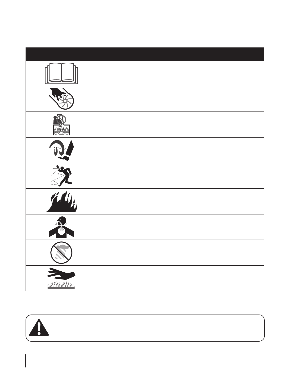
Do not put hands or feet near rotating parts, in the auger/1.
impeller housing or chute assembly. Contact with the
rotating parts can amputate hands and feet.
The auger/impeller control lever is a safety device. Never2.
bypass its operation. Doing so makes the machine unsafe
and may cause personal injury.
The control levers must operate easily in both directions3.
and automatically return to the disengaged position when
released.
Never operate with a missing or damaged chute assembly.4.
Keep all safety devices in place and working.
Never run an engine indoors or in a poorly ventilated area.5.
Engine exhaust contains carbon monoxide, an odorless
and deadly gas.
Do not operate machine while under the influence of6.
alcohol or drugs.
Muffler and engine become hot and can cause a burn. Do7.
not touch. Keep children away.
Exercise extreme caution when operating on or crossing8.
gravel surfaces. Stay alert for hidden hazards or traffic.
Exercise caution when changing direction and while9.
operating on slopes.
Plan your snow-throwing pattern to avoid discharge 10.
towards windows, walls, cars etc. Thus, avoiding possible
property damage or personal injury caused by a ricochet.
Never direct discharge at children, bystanders and pets or11.
allow anyone in front of the machine.
Do not overload machine capacity by attempting to clear12.
snow at too fast of a rate.
Never operate this machine without good visibility or light.13.
Always be sure of your footing and keep a firm hold on the
handles. Walk, never run.
Disengage power to the auger/impeller when transporting14.
or not in use.
Never operate machine at high transport speeds on15.
slippery surfaces. Look down and behind and use care
when backing up.
If the machine should start to vibrate abnormally, stop16.
the engine, disconnect the spark plug wire and ground it
against the engine. Inspect thoroughly for damage. Repair
any damage before starting and operating.
Disengage all control levers and stop engine before you17.
leave the operating position (behind the handles). Wait
until the auger/impeller comes to a complete stop before
unclogging the chute assembly, making any adjustments,
or inspections.
Never put your hand in the discharge or collector openings.18.
Always use the clean-out tool provided to unclog the
discharge opening. Do not unclog chute assembly while
engine is running. Shut off engine and remain behind
handles until all moving parts have stopped before
unclogging.
Use only attachments and accessories approved by the19.
manufacturer (e.g. wheel weights, tire chains, cabs etc.).
When starting engine, pull cord slowly until resistance20.
is felt, then pull rapidly. Rapid retraction of starter cord
(kickback) will pull hand and arm toward engine faster than
you can let go. Broken bones, fractures, bruises or sprains
could result.
If situations occur which are not covered in this manual, use21.
care and good judgment. Contact Customer Support for
assistance and the name of your nearest servicing dealer.

5se c t i O n 2 — iM p O r t a n t sa f e Op e r a t i O n pr a c t i c e s
Clearing a Clogged Discharge Chute
Hand contact with the rotating impeller inside the discharge
chute is the most common cause of injury associated with snow
throwers. Never use your hand to clean out the discharge chute.
To clear the chute:
SHUT THE ENGINE OFF!1.
Wait 10 seconds to be sure the impeller blades have2.
stopped rotating.
Always use a clean-out tool, not your hands.3.
Maintenance & Storage
Never tamper with safety devices. Check their proper1.
operation regularly. Refer to the maintenance and
adjustment sections of this manual.
Before cleaning, repairing, or inspecting machine 2.
disengage all control levers and stop the engine. Wait until
the auger/impeller come to a complete stop. Disconnect
the spark plug wire and ground against the engine to
prevent unintended starting.
Check bolts and screws for proper tightness at frequent3.
intervals to keep the machine in safe working condition.
Also, visually inspect machine for any damage.
Do not change the engine governor setting or over-speed4.
the engine. The governor controls the maximum safe
operating speed of the engine.
Snow thrower shave plates and skid shoes are subject to5.
wear and damage. For your safety protection, frequently
check all components and replace with original equipment
manufacturer’s (OEM) parts only. “Use of parts which do
not meet the original equipment specifications may lead to
improper performance and compromise safety!”
Check control levers periodically to verify they engage6.
and disengage properly and adjust, if necessary. Refer
to the adjustment section in this operator’s manual for
instructions.
Maintain or replace safety and instruction labels, as7.
necessary.
Observe proper disposal laws and regulations for gas, oil, 8.
etc. to protect the environment.
Prior to storing, run machine a few minutes to clear snow 9.
from machine and prevent freeze up of auger/impeller.
Never store the machine or fuel container inside where10.
there is an open flame, spark or pilot light such as a water
heater, furnace, clothes dryer etc.
Always refer to the operator’s manual for proper 11.
instructions on off-season storage.
Check fuel line, tank, cap, and fittings frequently for cracks12.
or leaks. Replace if necessary.
Do not crank engine with spark plug removed.13.
According to the Consumer Products Safety Commission 14.
(CPSC) and the U.S. Environmental Protection Agency (EPA),
this product has an Average Useful Life of seven (7) years,
or 60 hours of operation. At the end of the Average Useful
Life have the machine inspected annually by an authorized
service dealer to ensure that all mechanical and safety
systems are working properly and not worn excessively.
Failure to do so can result in accidents, injuries or death.
Do not modify engine
To avoid serious injury or death, do not modify engine in any
way. Tampering with the governor setting can lead to a runaway
engine and cause it to operate at unsafe speeds. Never tamper
with factory setting of engine governor.
Notice Regarding Emissions
Engines which are certified to comply with California and federal
EPA emission regulations for SORE (Small Off Road Equipment)
are certified to operate on regular unleaded gasoline, and
may include the following emission control systems: Engine
Modification (EM), Oxidizing Catalyst (OC), Secondary Air
Injection (SAI) and Three Way Catalyst (TWC) if so equipped.
Spark Arrestor
WARNING! This machine is equipped with an
internal combustion engine and should not be used
on or near any unimproved forest-covered, brush
covered or grass-covered land unless the engine’s
exhaust system is equipped with a spark arrester
meeting applicable local or state laws (if any).
If a spark arrester is used, it should be maintained in effective
working order by the operator. In the State of California the
above is required by law (Section 4442 of the California Public
Resources Code). Other states may have similar laws. Federal laws
apply on federal lands.
A spark arrester for the muffler is available through your
nearest engine authorized service dealer or contact the service
department, P.O. Box 361131 Cleveland, Ohio 44136-0019.

6se c t i O n 2 — iM p O r t a n t sa f e Op e r a t i O n pr a c t i c e s
Safety Symbols
This page depicts and describes safety symbols that may appear on this product. Read, understand, and follow all instructions on the
machine before attempting to assemble and operate.
Symbol Description
READ THE OPERATOR’S MANUAL(S)
Read, understand, and follow all instructions in the manual(s) before attempting to
assemble and operate
WARNING— ROTATING BLADES
Keep hands out of inlet and discharge openings while machine is running. There are rotating
blades inside
WARNING— ROTATING BLADES
Keep hands out of inlet and discharge openings while machine is running. There are rotating
blades inside
WARNING— ROTATING AUGER
Do not put hands or feet near rotating parts, in the auger/impeller housing or chute
assembly. Contact with the rotating parts can amputate hands and feet.
WARNING—THROWN OBJECTS
This machine may pick up and throw objects which can cause serious personal injury.
WARNING—GASOLINE IS FLAMMABLE
Allow the engine to cool at least two minutes before refueling.
WARNING— CARBON MONOXIDE
Never run an engine indoors or in a poorly ventilated area. Engine exhaust contains carbon
monoxide, an odorless and deadly gas.
WARNING— ELECTRICAL SHOCK
Do not use the engine’s electric starter in the rain
WARNING— HOT SURFACE
Engine parts, especially the muffler, become extremely hot during operation. Allow engine
and muffler to cool before touching.
WARNING! Your Responsibility—Restrict the use of this power machine to persons who read, understand and
follow the warnings and instructions in this manual and on the machine.
SAVE THESE INSTRUCTIONS!

Assembly & Set-Up 3
7
Assembly
Handle
Observe the lower rear area of the snow thrower to be sure 1.
both cables are aligned with roller guides before pivoting
the handle upward. See Fig. 3-1.
NOTE: Make certain the upper ends of each cable are
seated properly in its pulley. See Fig. 3-2.
Secure the handle by tightening the plastic knob located2.
on both the left and right sides of the handle. Remove
and discard any rubber bands, if present. They are for
packaging purposes only.
Chute Assembly
Position the chute assembly over the base. See Fig. 3-3.1.
Contents of Carton
One Snow Thrower• Two Replacement Auger Shear Pins• One Chute Assembly•
One Snow Thrower Operator’s •
Manual
One Engine Operator’s Manual• One Product Registration Card•
Figure 3-2
Figure 3-3
Figure 3-1

8se c t i O n 2— as s e M b l y & se t -up
Close the flange keepers to secure the chute assembly2.
to the chute base. The flange keepers will click into place
when properly secure. See Fig. 3-4.
NOTE: If the flange keepers will not easily click into place,
use the palm of your hand to apply swift, firm pressure to
the back of each.
Chute Directional Control
Remove the plastic cap (if present), flat washer and hairpin1.
clip from the end of the chute directional control. See
Fig. 3-5.
Insert the end of the chute directional control into the2.
lower bracket and secure with the flat washer and hairpin
clip just removed. If necessary, the lower bracket can be
adjusted. Refer to Chute Bracket Adjustment on page 15.
Set-Up
Shear Pins
A pair of replacement auger shear pins and bow tie cotter pins
are included with your snow thrower. Store them in a safe place
until needed. See Fig. 3-6.
Chute Clean-Out Tool
The chute clean-out tool is fastened to the top of the auger
housing with a mounting clip and a cable tie at the factory. Cut
the cable tie before operating the snow thrower. See Fig. 3-7.
Chute Clean-Out Tool
Figure 3-7
Figure 3-4
Figure 3-5
Figure 3-6

9se c t i O n 2 — as s e M b l y & se t -up
Tire Pressure
WARNING: Under any circumstance do not exceed
manufacturer’s recommended psi. Equal tire
pressure should be maintained at all times. Excessive
pressure when seating beads may cause tire/rim
assembly to burst with force sufficient to cause
serious injury. Refer to side wall of tire for
recommended pressure.
The tires are over-inflated for shipping purposes. Check the tire
pressure before operating the snow thrower. Refer to the tire side
wall for tire manufacturer’s recommended psi and deflate (or
inflate) the tires as necessary.
NOTE: If the tire pressure is not equal in both tires, the machine may
not travel in a straight path and the shave plate may wear unevenly.
Adjustments
Skid Shoes
The snow thrower skid shoes are adjusted upward at the factory
for shipping purposes. Adjust them downward, if desired, prior
to operating the snow thrower.
CAUTION: It is not recommended that you operate
this snow thrower on gravel as it can easily pick up
and throw loose gravel, causing personal injury or
damage to the snow thrower and surrounding
property.
For close snow removal on a smooth surface, raise skid•
shoes higher on the auger housing.
Use a middle or lower position when the area to be cleared•
is uneven, such as a gravel driveway.
NOTE: If you choose to operate the snow thrower on a gravel
surface, keep the skid shoes in position for maximum clearance
between the ground and the shave plate.
To adjust the skid shoes:
Loosen the four hex nuts (two on each side) and carriage1.
bolts. Move skid shoes to desired position. See Fig. 3-8.
Make certain the entire bottom surface of skid shoe is2.
against the ground to avoid uneven wear on the skid shoes.
Retighten nuts and bolts securely.3.
Chute Assembly
The distance snow is thrown can be adjusted by changing the
angle of the chute assembly. To do so:
Stop the engine. Refer to the Engine Operator’s Manual.1.
Remove the key and loosen the plastic knob found on the
left side of the chute assembly.
Pivot the chute upward or downward before retightening 2.
the wing knob. See Fig. 3-9.
Figure 3-8
Figure 3-9

10 se c t i O n 2— as s e M b l y & se t -up
Auger Control
WARNING! Prior to operating your snow thrower,
carefully read and follow all instructions below.
Perform all adjustments to verify your snow thrower
is operating safely and properly.
Check the adjustment of the auger control as follows:
When the auger control is released and in the disengaged1.
“up” position, the cable should have very little slack. It
should NOT be tight.
In a well-ventilated area, start the snow thrower engine.2.
Refer to your Engine Operator’s Manual.
While standing in the operator’s position (behind the snow 3.
thrower), engage the auger.
Allow the auger to remain engaged for approximately ten4.
(10) seconds before releasing the auger control. Repeat this
several times.
With the throttle control in the FAST (rabbit) position and5.
the auger control in the disengaged “up” position, walk to
the front of the machine.
Confirm that the auger has completely stopped rotating6.
and shows NO signs of motion. If the auger shows ANY
signs of rotating, immediately return to the operator’s
position and shut off the engine as instructed in the Engine
Operator’s Manual. Wait for ALL moving parts to stop
before re-adjusting the auger control.
To readjust the control cable, loosen the upper hex screw7.
on the auger cable bracket. See Fig. 3-10.
Position the bracket upward to provide more slack (or 8.
downward to increase cable tension).
Retighten the upper hex screw.9.
Repeat steps 2 through 6 above to verify proper10.
adjustment has been achieved.
Figure 3-10

Controls & Features 4
11
Snow thrower controls and features are described below and
illustrated in Fig. 4-1.
Skid Shoes
Position the skid shoes based on surface conditions. Adjust
upward for hard-packed snow. Adjust downward when
operating on gravel or crushed rock surfaces.
Augers
When engaged, the augers rotate and draw snow into the auger
housing.
Chute Assembly
Snow drawn into the auger housing is discharged out the chute
assembly.
Figure 4-1
Augers Skid Shoe
Chute Clean
Out Tool
Chute Assembly
Drive Control
Chute Directional
Control
Auger Control
Chute Directional Control
The chute directional control is located on the left side of the
snow thrower. To change the direction in which snow is thrown,
rotate the chute directional control.

12 se c t i O n 4— cO n t r O l s & fe a t u r e s
Auger Control
The auger control is located on the left handle. Squeeze the
control grip against the handle to engage the augers and start
snow throwing action. Release to stop.
Drive Control
The drive control is located on the right handle. Squeeze the
control grip against the handle to engage the wheel drive.
Release to stop.
Chute Clean-Out Tool
WARNING! Never use your hands to clear a
clogged chute assembly. Shut off engine and remain
behind handles until all moving parts have stopped
before unclogging.
The chute clean-out tool is conveniently fastened to the rear of
the auger housing with a mounting clip. Should snow and ice
become lodged in the chute assembly during operation, proceed
as follows to safely clean the chute assembly and chute opening:
Release both the Auger Control and the Drive Control.1.
Stop the engine as instructed in the Engine Operator’s 2.
Manual. Remove the key.
Remove the clean-out tool from the clip which secures it to3.
the rear of the auger housing.
Use the shovel-shaped end of the clean-out tool to4.
dislodge and scoop any snow and ice which has formed in
and near the chute assembly.
Refasten the clean-out tool to the mounting clip on5.
the rear of the auger housing, reinsert the key and start
the snow thrower’s engine as instructed in the Engine
Operator’s Manual.
While standing in the operator’s position (behind the snow
thrower), engage the auger control for a few seconds to clear any
remaining snow and ice from the chute assembly.

Operation 5
13
Starting and Stopping the Engine
Refer to the Engine Operator’s Manual packed with your snow
thrower for instructions on starting and stopping the engine.
To Engage Augers
To engage the augers and start throwing snow, squeeze the
auger control against the left handle. Release to stop the augers.
Replacing Shear Pins
The augers are secured to the spiral shaft with two shear pins
and cotter pins. If the auger should strike a foreign object or ice
jam, the snow thrower is designed so that the pins may shear. If
the augers will not turn, check to see if the pins have sheared.
See Fig. 5-1.
CAUTION: NEVER replace the auger shear pins with
anything other than OEM Part No. 738-04124A
replacement shear pins. Any damage to the auger
gearbox or other components as a result of failing to
do so will NOT be covered by your snow thrower’s
warranty.
WARNING! Always turn off the snow thrower’s
engine and remove the key prior to replacing shear
pins.
Figure 5-1

Maintenance
Engine
Refer to the Engine Operator’s Manual.
Shave Plate and Skid Shoes
The shave plate and skid shoes on the bottom of the snow
thrower are subject to wear. They should be checked periodically
and replaced when necessary.
To remove skid shoes:
Remove the four carriage bolts and hex flange nuts which1.
secure them to the snow thrower.
Reassemble new skid shoes with the four carriage bolts2.
(two on each side) and hex flange nuts. Refer to Fig. 6-1.
To remove shave plate:
Remove the carriage bolts and hex nuts which attach it to1.
the snow thrower housing.
Reassemble new shave plate, making sure heads of carriage2.
bolts are to the inside of housing. Tighten securely.
Tire Pressure
Refer to page 9 for information regarding tire pressure.
Lubrication
Wheels
At least once a season, remove both wheels. Clean and coat the
axles with a multipurpose automotive grease before reinstalling
wheels.
Chute Directional Control
Once a season, lubricate the eye-bolt bushing and the spiral with
3-in-1 oil.
Auger Shaft
At least once a season, remove the shear pins from the auger
shaft. Spray lubricant inside the shaft and around the spacers
and the flange bearings found at either end of the shaft. Reinstall
shear pins. See Fig. 6-2.
Adjustments
Auger Control
Refer to the Assembly and Set-up section for instructions on
adjusting the auger control cable.
Chute Assembly
Refer to the Assembly and Set-up section for instructions on
adjusting the skid shoes chute assembly.
Skid Shoes
Refer to the Assembly and Set-up section for instructions on
adjusting the skid shoes.
NOTE: Augers not shown for clarity
Figure 6-1 Figure 6-2
Maintenance & Adjustments 6
14

Drive Control
When the drive control is released and in the disengaged “up”
position, the cable should have very little slack. It should NOT be
tight.
NOTE: If excessive slack is present in the drive cable or if the snow
thrower’s drive is disengaging intermittently during operation,
the cable may be in need of adjustment.
Check the adjustment of the drive control as follows:
With the drive control released, push the snow thrower1.
gently forward. The unit should roll freely.
Engage the drive control and gently attempt to push the2.
snow thrower forward. The wheels should not turn. The
unit should not roll freely.
If either of the above tests failed, the drive cable is in need of
adjustment. Proceed as follows:
Loosen the lower hex screw on the drive cable bracket. See1.
Fig. 6-3.
Position the bracket upward to provide more slack (or 2.
downward to increase cable tension).
Retighten the upper hex screw.3.
Check the adjustment of the drive control as described4.
above.
Chute Bracket Adjustment
If the spiral at the bottom of the chute directional control is not
fully engaging with the chute assembly, the chute bracket can be
adjusted. To do so:
Loosen the two nuts which secure the chute bracket and1.
reposition it slightly. See Fig. 6-4.
Retighten the nuts.2.
Off-Season Storage
If the snow thrower will not be used for 30 days or longer, follow
the storage instructions below.
Run the engine until the fuel tank is empty and it stops due1.
to lack of fuel. Do not attempt to pour fuel from the engine.
Lubricate the machine as instructed earlier in this section.2.
Store in a clean, dry area.3.
If storing the snow thrower in an unventilated area,4.
rustproof the machine using a light oil or silicone to coat
the snow thrower.
Clean the exterior of the engine and the snow thrower.5.
NOTE: Refer to the Engine Operator’s Manual for information on
storing your engine.
Figure 6-3
Figure 6-4
15se c t i O n 6 — Ma i n t e n a n c e & ad j u s t M e n t s

Belt Replacement
Auger Belt
To remove and replace your snow thrower’s auger belt, proceed
as follows:
Allow the engine to run until it is out of fuel. Do not1.
attempt to pour fuel from the engine.
Remove the plastic belt cover on the front of the engine by2.
removing the two self-tapping screws. See Fig. 7-1.
Roll the auger belt off the engine pulley. See Fig. 7-2.3.
Carefully pivot the snow thrower up and forward so that it4.
rests on the auger housing.
Remove the frame cover from the underside of the snow5.
thrower by removing the self-tapping screws which secure
it. See Fig. 7-3.
Remove the belt as follows. See Fig. 7-4.6.
Loosen and remove the shoulder bolt which acts asa.
a belt keeper.
Unhook the support bracket spring from the frame.b.
Figure 7-3
Figure 7-1
Figure 7-2
Figure 7-4
Service 7
16

Remove the belt from around the auger pulley, and slip the7.
belt between the support bracket and the auger pulley.
See Fig. 7-5.
Replace the auger belt by following instructions in reverse8.
order.
NOTE: Do not forget to reinstall the shoulder bolt and
reconnect the spring to the frame after installing a
replacement auger belt.
After replacing the auger belt, perform the Auger Control9.
test on page 10 of the Assembly and Set-Up section.
Drive Belt
To remove and replace your snow thrower’s drive belt, proceed
as follows:
To prevent spillage, remove all fuel from tank by running1.
engine until it stops. Do not attempt to pour fuel from the
engine.
Remove the plastic belt cover on the front of the engine by2.
removing the two self-tapping screws. Refer to Fig. 7-1.
Remove the belt as follows. See Fig. 7-6:3.
Roll the auger belt off the engine pulley.a.
Pivot the idler pulley toward the right. See Fig. 7-6. b.
Lift the drive belt off engine pulley.c.
Carefully pivot the snow thrower up and forward so that it4.
rests on the auger housing.
Remove the frame cover from the underside of the snow5.
thrower by removing the self-tapping screws which secure
it. Refer to Fig. 7-3.
C
B
A
Figure 7-6
Figure 7-5
17se c t i O n 7 — se r v i c e

Back out the stop bolt to increase the clearance between 6.
the friction wheel disc and friction wheel. See Fig. 7-7.
Slip the drive belt off the pulley and between friction7.
wheel and friction wheel disc. See Fig. 7-7.
Remove and replace belt in the reverse order.8.
Reinstall the stop bolt.9.
Friction Wheel Inspection
If the snow thrower fails to drive with the drive control engaged,
and performing the drive control cable adjustment fails to
correct the problem, the friction wheel may need to be replaced.
NOTE: Special tools are required and several components must
be removed and in order to replace the snow thrower’s friction
wheel rubber. See your authorized service dealer to have the
friction wheel rubber replaced or phone Customer Support
as instructed on page 2 for information on ordering a Service
Manual.
To inspect the friction wheel, proceed as follows:
Allow the engine to run until it is out of fuel. Do not1.
attempt to pour fuel from the engine.
Carefully pivot the snow thrower up and forward so that it2.
rests on the auger housing.
Remove the frame cover from the underside of the snow3.
thrower by removing four self-tapping screws which secure
it. See Fig. 7-8.
Examine the friction wheel for signs of wear or cracking.4.
Stop Bolt
Figure 7-7
Figure 7-8
18 se c t i O n 7 — se r v i c e

Troubleshooting 8
19
Problem Cause Remedy
Engine fails to start Choke not in CHOKE position.1.
Spark plug wire disconnected.2.
Fuel tank empty or stale fuel.3.
Engine not primed.4.
Faulty spark plug.5.
Key not in ignition on engine.6.
Move choke to CHOKE position.1.
Connect wire to spark plug.2.
Fill tank with clean, fresh gasoline.3.
Prime engine as instructed in the Engine 4.
Operator’s Manual.
Clean, adjust gap, or replace.5.
Insert key fully into the switch.6.
Engine running erratically/
inconsistent RPM (hunting
or surging)
Engine running on CHOKE.1.
Stale fuel.2.
Water or dirt in fuel system.3.
Carburetor out of adjustment.4.
Engine over-governed5.
Move choke lever to RUN position.1.
Fill tank with clean, fresh gasoline.2.
Drain fuel tank. Refill with fresh fuel.3.
Contact an authorized Service Center.4.
Contact an authorized Service Center.5.
Engine overheats Carburetor not adjusted properly.1. Contact an authorized Service Center.1.
Excessive vibration Loose parts or damaged auger.1. Stop engine immediately and disconnect1.
spark plug wire. Tighten all bolts and nuts. If
vibration continues, have unit serviced by an
authorized Service Center.
Loss of power Spark plug wire loose.1.
Gas cap vent hole plugged.2.
Connect and tighten spark plug wire.1.
Remove ice and snow from gas cap. Be 2.
certain vent hole is clear.
Unit fails to propel itself Drive control cable in need of adjustment.1.
Drive belt loose or damaged.2.
Friction wheel worn.3.
Adjust drive control cable. Refer to1.
Maintenance & Adjustments section.
Replace drive belt. Refer to Service section2.
Replace friction wheel. Refer to Service3.
section.
Unit fails to discharge snow Chute assembly clogged.1.
Foreign object lodged in auger.2.
Auger control cable in need of adjustment.3.
Auger belt loose or damaged.4.
Shear pin(s) sheared.5.
Stop engine immediately and disconnect1.
spark plug wire. Clean chute assembly and
inside of auger housing with clean-out tool
or a stick.
Stop engine immediately and disconnect2.
spark plug wire. Remove object from auger
with clean-out tool or a stick.
Refer to Auger Control Test.3.
Refer to Maintenance & Adjustments section.4.
Replace with new shear pin(s).5.
Chute fails to easily rotate
180 degrees
Chute assembled incorrectly.1. Unassemble chute control and reassemble as1.
directed in the Assembly section.

Phone (800) 800-7310 to order replacement parts or a complete Parts Manual (have your full model number and serial number ready).
Parts Manual downloads are also available free of charge at www.mtdproducts.com.
Component Part Number and Description
954-04050 Auger Drive Belt
954-04260 Wheel Drive Belt
784-5580 Slide Shoe, Standard
738-04124A Shear Pin, 1.50
714-04040 Bow-tie Cotter Pin
931-2643 Chute Clean-out Tool
790-00117 Shave Plate, 22”
731-05632 Key
951-10292 Spark Plug
Replacement Parts 9
20
Table of contents
Other MTD Snow Blower manuals

MTD
MTD Troy-Bilt 3BB User manual

MTD
MTD Cub Cadet 221 HP User manual

MTD
MTD 600-Series L Style User manual

MTD
MTD Cub Cadet E 22 User manual

MTD
MTD 310-600 User manual

MTD
MTD 31AM62EE000 User manual

MTD
MTD K Style User manual

MTD
MTD 313-205 User manual

MTD
MTD 311-500A User manual

MTD
MTD 31AS6BN2711 User manual