Operation
1. Donot puthandsorfeet nearrotatingparts,inthe
auger/impellerhousingor chuteassembly.Contactwiththe
rotatingpartscanamputatehandsandfeet.
2. The auger/impellercontrolleveris asafetydevice.Never
bypassitsoperation.Doingsomakesthe machineunsafe
andmaycausepersonalinjury.
3. The controlleversmustoperateeasilyin bothdirections
and automaticallyreturntothe disengagedpositionwhen
released.
4. Neveroperatewitha missingor damagedchuteassembly.
Keepall safetydevicesin placeandworking.
5. Neverrunan engineindoorsor in apoorlyventilatedarea.
Engineexhaustcontainscarbonmonoxide,anodorlessand
deadlygas.
6. Donotoperatemachinewhile underthe influenceofalcohol
or drugs.
7. Mufflerandenginebecomehotandcan causeaburn.Do
nottouch.
8. Exerciseextremecautionwhenoperatingonor crossing
gravelsurfaces.Stayalertforhiddenhazardsortraffic.
9. Exercisecautionwhenchangingdirectionandwhileoperat-
ingonslopes.
10.Planyoursnow-throwingpatternto avoiddischargetowards
windows,walls,carsetc.Thus,avoidingpossibleproperty
damageor personalinjury causedbyaricochet.
11.Neverdirectdischargeatchildren,bystandersandpetsor
allow anyonein frontofthe machine.
12.Donotoverloadmachinecapacity byattemptingto clear
snowattoofast ofarate.
13.Neveroperatethis machinewithoutgoodvisibilityor light.
Alwaysbesureofyourfootingand keepafirm holdonthe
handles.Walk,neverrun.
14.Disengagepowerto the auger/impellerwhentransportingor
notin use.
15.Neveroperatemachineat hightransportspeedsonslippery
surfaces.Lookdownand behindandusecarewhen
backingup.
16.Ifthe machineshouldstartto vibrateabnormally,stopthe
engine,disconnectthe sparkplugwireandgroundit against
the engine.Inspectthoroughlyfordamage.Repairany
damagebeforestartingandoperating.
17.Disengageallcontrolleversandstopenginebeforeyou
leavethe operatingposition(behindthe handles).Wait
untilthe auger/impellercomestoa completestop before
uncloggingthe chuteassembly,makinganyadjustments,or
inspections.
18.Neverputyourhandin thedischargeor collectoropenings.
Alwaysusethe clean-outtoolprovidedtounclogthe dis-
chargeopening.Donot unclogchuteassemblywhileengine
isrunning.Shutoffengineandremainbehindhandlesuntil
all movingpartshavestoppedbeforeunclogging.
19.Useonlyattachmentsandaccessoriesapprovedbythe
manufacturer(e.g.wheelweights,tire chains,cabsetc.).
20. Ifsituationsoccurwhicharenotcoveredin this manual,use
careandgoodjudgment.Callcustomerassistanceforthe
nameof yournearestservicingdealer.
Maintenance & Storage
1. Nevertamperwithsafetydevices.Checktheirproper
operationregularly.Refertothe maintenanceandadjust-
mentsectionsofthis manual.
2. Beforecleaning,repairing,or inspectingmachinedisengage
allcontrolleversandstopthe engine.Waituntilthe
auger/impellercometo acompletestop.Disconnectthe
sparkplugwireand groundagainstthe engineto prevent
unintendedstarting.
3. Checkboltsand screwsforpropertightnessatfrequent
intervalsto keepthe machinein safeworkingcondition.
Also,visuallyinspectmachineforanydamage.
4. Do notchangethe enginegovernorsettingor over-speed
theengine.Thegovernorcontrolsthemaximumsafe
operatingspeedoftheengine.
5. Snowthrowershaveplatesandskidshoesaresubjectto
wearanddamage.Foryoursafetyprotection,frequently
checkallcomponentsand replacewith originalequipment
manufacturer's(OEM)partsonly."Useof partswhichdo
notmeetthe originalequipmentspecificationsmayleadto
improperperformanceandcompromisesafety!"
6. Checkcontrolsperiodicallytoverify theyengageand
disengageproperlyandadjust,if necessary.Referto the
adjustmentsectioninthisoperator'smanualfor instructions.
7. Maintainor replacesafetyandinstructionlabels,as neces-
sary.
8. Observeproperdisposallawsandregulationsforgas,oil,
etc.toprotectthe environment.
9. Priorto storing,runmachinea few minutestoclearsnow
frommachineandpreventfreezeupof auger/impeller.
10.Neverstorethe machineorfuel containerinsidewhere
thereisan openflame,sparkor pilotlightsuchas a water
heater,furnace,clothesdryeretc.
11.Alwaysreferto theoperator'smanualfor properinstructions
onoff-seasonstorage.
Do not modify engine
Toavoidseriousinjuryordeath,donot modifyengineinany
way.Tamperingwiththegovernorsettingcan leadto arunaway
engineandcauseit tooperateatunsafespeeds.Nevertamper
withfactorysettingofenginegovernor.
Notice regarding Emissions
Engineswhicharecertifiedto complywithCaliforniaandfederal
EPAemissionregulationsfor SORE(SmallOff RoadEquipment)
arecertifiedtooperateonregularunleadedgasoline,and may
includethefollowingemissioncontrolsystems:EngineModifica-
tion(EM)andThreeWayCatalyst(TWO)ifsoequipped.
Average Useful Life
Accordingtothe ConsumerProductsSafetyCommission
(CPSC)andthe U.S.EnvironmentalProtectionAgency(EPA),
thisproducthasanAverage UsefulLife ofseven(7)years,or
60hoursof operation.Attheend oftheAverage UsefulLife,
buya newmachineor havethe machineinspectedannuallyby
anauthorizedservicedealertoensurethat all mechanicaland
safetysystemsareworkingproperlyandnotwornexcessively.
Failuretodoso canresultin accidents,injuriesordeath.
5
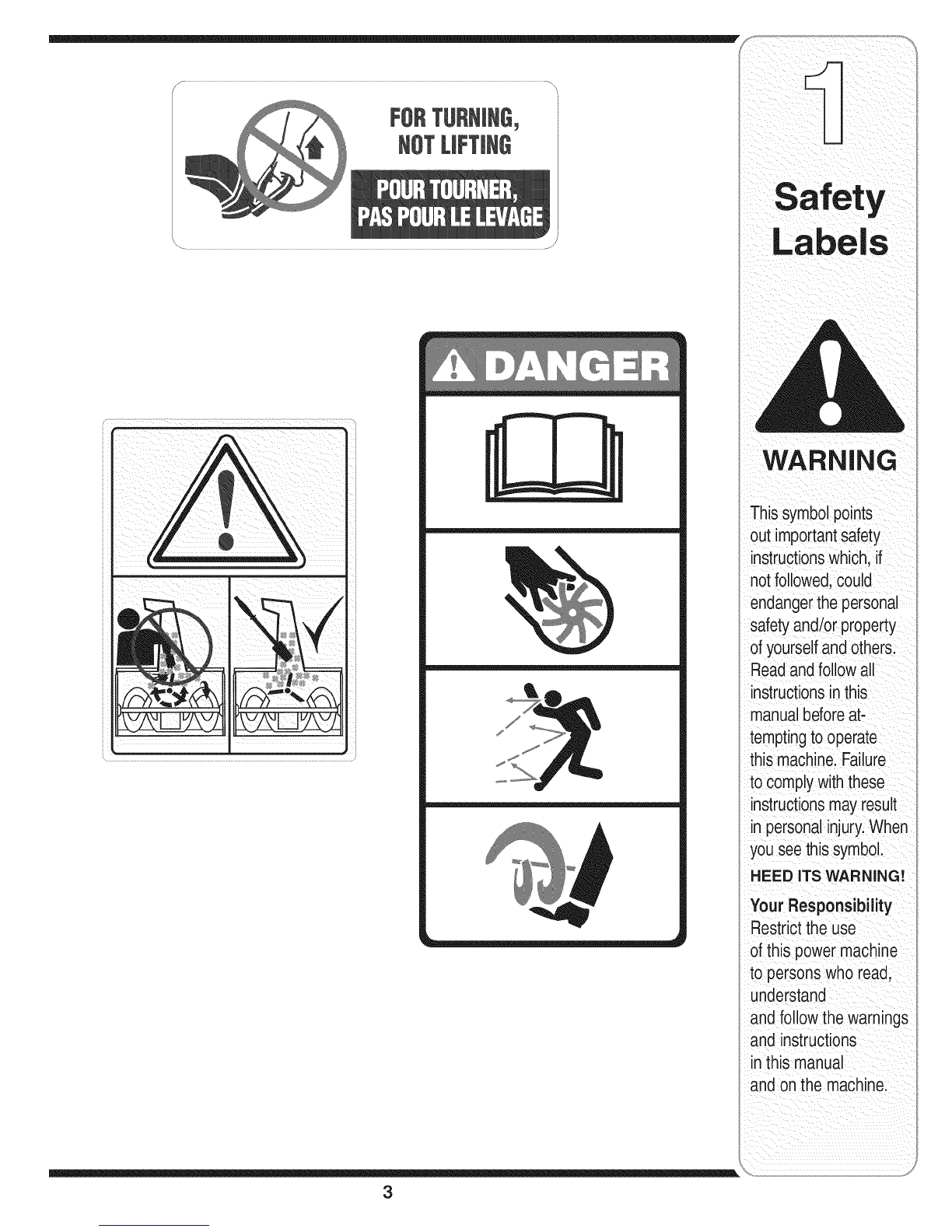
WARNING
This symbol points
out important safety
instructions,which
if not followed, could
endanger the per-
sonalsafety and/or
property of yourself
and others. Read and
follow all instructions
in this rnanuai before
attempting to operate
this machine. Failure
to complywith these
instructionsmay
result in personal
injury.When you see
this symbol, HEED
IT'S WARNING!
Your Responsibility
Restrictthe use
ofthis powermachine
to personswho read,
understand
and followthe warnings
and instructions
in this manual
and onthe machine.