MTD Cub Cadet E 22 User manual

769-20912B
MTD Products Aktiengesellschaft • Saarbrücken • Germany
E 22


E
D
C
AB
AB
1
2
A
A

9 - 10mm
max.

3
8
2
6
17 5
4
1

Typ 1
Typ 2
Typ 3
109
111
113

4
13
24
34
44
54
63
72
81
90
99

English Operating manual for snow thrower
4
Contents
For your safety . . . . . . . . . . . . . . 4
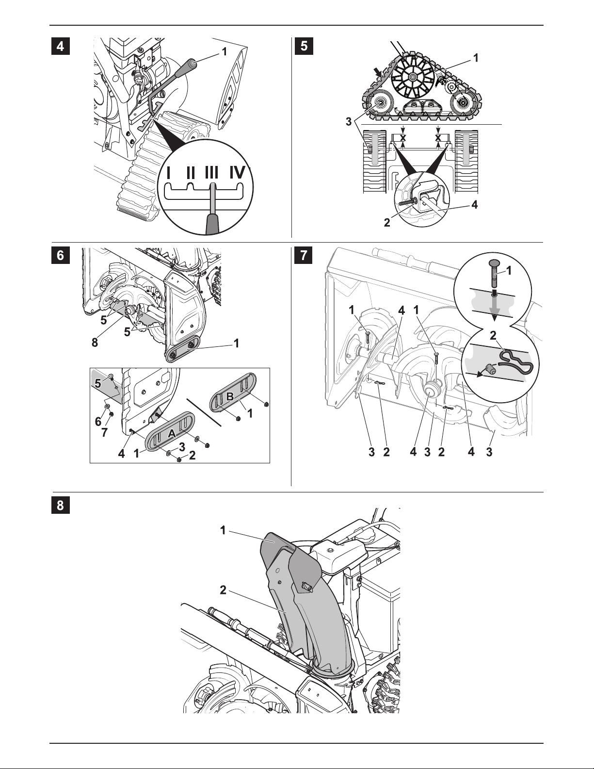
Unpacking and assembly . . . . . . 5
Before using the machine
for the first time . . . . . . . . . . . . . . 5
Always adjust machine
before using . . . . . . . . . . . . . . . . 6
Operating the machine . . . . . . . . 6
Transportation . . . . . . . . . . . . . . . 8
Maintenance . . . . . . . . . . . . . . . . 9
Preparing the machine
for non-use . . . . . . . . . . . . . . . . 11
Warranty . . . . . . . . . . . . . . . . . . 11
Engine . . . . . . . . . . . . . . . . . . . . 11
Troubleshooting. . . . . . . . . . . . . 11
Information on the
identification plate
This information is very important
for later identification of the machine
when ordering spare parts and when
using the Customer Service.
You will find the identification plate
in the vicinity of the engine.
Copy all the information on this
identification plate into the following
space.
This and other appliance information
can be found on the separate
CE declaration of conformity which
is a component of these operating
instructions.
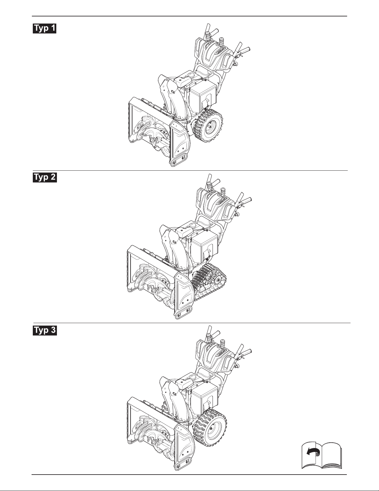
Various models are described in
these operating instructions.
Models are designated as Type 1 to
Type 3 (see overview of units on the
front fold-out pages).
The graphical representations may
differ in detail from the unit which
you purchased.
For your safety
Use the machine
properly
This machine is designed exclusively
for use
– as a snow thrower for the removal
of snow from reinforced paths
and areas around the house and
recreation ground,
– in accordance with the descrip-
tions and safety instructions
indicated in this operating manual.
Any other use is not as intended.
Improper use is not covered by the
warranty and the manufacturer will
reject any liability. The user is liable
for any injuries to third parties and/or
damage to their property.
Unauthorised changes to the unit
exclude liability of the manufacturer
for any resulting damage and/or injury.
General notes on safety
As user of this machine, read these
operating instructions through care-
fully before using the machine for the
first time. Follow these instructions
and keep them safe for later use
or in case of a change of ownership.
Do not allow any person under the
age of 16 to handle this machine
(it is possible that local regulations
define the minimum age of the user).
This appliance is not intended for use
by persons (including children) with
reduced physical, sensory or mental
capabilities, or lack of experience and
knowledge, unless they have been
given supervision or instruction con-
cerning use of the appliance by
a person responsible for their safety.
Children should be supervised
to ensure that they do not play with
the appliance.
Keep other people, especially
children, and domestic animals
away from the danger area.
Pay attention to national regulations
in force if you are in charge of the
machine on public roads or paths.
Never use the machine to transport
someone.
Operate the unit only in the technical
condition stipulated and delivered
by the manufacturer.
Never change the engine settings
preset at the factory.
When working, wear gloves, hearing
protection, goggles, close-fitting
winter clothing and sturdy footwear
with non-slip soles.
Never refuel the machine in an en-
closed space or when the engine
is running or hot.
Never allow parts of the body
or clothing to come close to rotating
or hot parts of the machine.
Turn off the engine, remove the
ignition key and the spark-plug
connector whenever
– you are not working with
the machine,
– you leave it for a time or
– you make adjustments to it
or undertake maintenance
or repair work.
Let the engine cool down before
you park the machine in an en-
closed space.
Store the machine and fuel in a safe
place
– away from sources of fire (sparks,
flames),
– inaccessible to children.
Spare parts and accessories must
satisfy the requirements specified
by the manufacturer.
Therefore use original spare parts and
original accessories only or spare
parts and accessories authorised
by the manufacturer.
Replace a damaged exhaust, tank
or tank cap.
Have the machine repaired only
by a professional workshop.
Safety features
Fig. 1
Safety devices are provided for your
protection and must always function
properly. You may not remove,
change or circumvent them.

Operating manual for snow thrower English
5
Clutch lever for the worm
drive (1)
The worm drive switches off if the
user releases this drive clutch lever.
This lever can be locked in the de-
pressed position (optional) if the user
presses and holds down the clutch
lever for the travel drive (2).
As soon as the user lets go of the
lever (2), both levers jump back;
worm drive and drive system are
simultaneously switched off.
Drive clutch lever for the
wheel drive (2)
The wheel drive switches off if the
user releases this drive clutch lever.
Protective grid in the
throw-out chute
The protective grid stops you from
reaching into the throw-out chute.
Discharge flap
Fig. 8
The discharge flap (1) prevents
injuries from ejected objects.
Symbols on the machine
At various places on the machine
you will find safety and warning
notices represented by symbols
or pictograms. The symbols have
the following precise meanings:
Caution!
Before switching on,
read the operating
instructions!
Beware of hot surface!
Warning – toxic
vapours!
Warning! Petrol is
flammable!
Risk of injury from
thrown-out snow
or solid objects!
Risk of electric shock!
If it is raining, do not use
the electric starter.
Risk of injury!
Keep hands and feet
away from rotating
parts. Prior to all work,
for example, clogging in
the discharge chute,
initially switch off the
device, pull out the
ignition key, and wait
until all moving parts
have come to a
standstill.
Clean discharge chute
with the cleaning tool
only.
Risk of injury!
Keep hands and feet
away from rotating
parts. Prior to all work,
for example, clogging in
the auger housing or on
the snow-throwing
auger, initially switch off
the device, pull out the
ignition key, and wait
until all moving parts
have come to a
standstill.
Clean discharge chute
and snow-throwing
auger with the cleaning
tool only.
QR code (classic
example)
If you find a QR code
on your device, scan
the QR code symbol
with a smartphone to
obtain information on
the warnings.
Replace any damaged or illegible
symbols.
Symbols in the user's
guide
Symbols are employed in the user's
guide to indicate hazards or draw
attention to important information.
They have the following specific
meanings:
a~åÖÉê
aê~ïë=óçìê=~ííÉåíáçå=íç=ëçìêÅÉë=
çÑ=éçíÉåíá~ä=Ç~åÖÉê=~ëëçÅá~íÉÇ=
ïáíÜ=íÜÉ=í~ëâ=óçì=~êÉ=ìåÇÉêí~âáåÖ=
~í=íÜÉ=íáãÉ=ïÜáÅÜ=ÅçåëíáíìíÉ=
~=Ç~åÖÉê=íç=éÉêëçåëK=
`~ìíáçå
rëÉÇ=íç=ÜáÖÜäáÖÜí=Ü~ò~êÇë=ïÜáÅÜ=~êÉ=
~ëëçÅá~íÉÇ=ïáíÜ=íÜÉ=~Åíáîáíó=íÜ~í=áë=
ÄÉáåÖ=ÇÉëÅêáÄÉÇI=ïÜÉêÉÄó=Ç~ã~ÖÉ=
ÅçìäÇ=çÅÅìê=íç=íÜÉ=~ééäá~åÅÉK
Note
This indicates important information
and application tips.
Unpacking and
assembly
The assembly of the unit is illustrated
at the end of the operating instruc-
tions or on a supplementary sheet.
Disposal instructions
Dispose of packaging remnants,
old machines, etc., in accordance
with local regulations.
Before using the
machine for the first
time
^ííÉåíáçå>
^äï~óë=ÅÜÉÅâ=íÜÉ=çáä=äÉîÉä=~åÇI=
áÑ=êÉèìáêÉÇI=Ñáää=ïáíÜLíçé=ìé=ÉåÖáåÉ=
çáä=EëÉÉ=lbåÖáåÉ=ã~åì~äÒFK
Check that the safety devices,
controls and associated clutch
cables and other cables as well
as all screw connections are not
damaged and are secure.
Replace damaged parts before
operating the unit.
!
!

English Operating manual for snow thrower
6
(Type 1 and type 3)
For transportation reasons, the
tyres may show a higher tyre
pressure. Check tyre pressure
and adjust accordingly.
Recommended tyre pressure:
1 bar.
Check clutch for auger drive and
traction drive (see “Maintenance”).
Check shift lever (see
“Maintenance”).
Always adjust machine
before using
oáëâ=çÑ=áåàìêó
_ÉÑçêÉ=ÇçáåÖ=~åó=ïçêâ=çå=íÜáë=
ã~ÅÜáåÉ
Ó qìêå=çÑÑ=íÜÉ=ÉåÖáåÉK
Ó t~áí=ìåíáä=~ää=ãçîáåÖ=é~êíë=Ü~îÉ=
ÅçãÉ=íç=~=ëí~åÇëíáääX=íÜÉ=ÉåÖáåÉ=
ãìëí=Ü~îÉ=ÅççäÉÇ=ÇçïåK
Ó oÉãçîÉ=íÜÉ=áÖåáíáçå=âÉó=~åÇ=íÜÉ=
ëé~êâJéäìÖ=ÅçååÉÅíçêK
Adjust the machine to
con-form to the ground
and snow conditions
Adjust working position
(Machines with caterpillar
drive)
Fig. 4
Use setting lever (1) to select
a position to match the conditions:
– Position I: For heavy snow which
has iced over. Worm is pressed
onto the ground.
– Position II: For normal snow
conditions.
– Position III: For clearing uneven
paths and crushed stone and
gravel paths.
– Position IV: For transporting the
unit. The auger is at a greater
distance from the ground.
Adjust the skids
Fig. 6
With the skids (1), the distance bet-
ween the ground and the clearing
plate (8) can be set in such a way that
no parts of the ground (e.g. earth
or stones) can be taken up.
(Machines with caterpillar drive)
Set setting lever (Fig. 4, Pos. 1)
to position II.
Loosen nuts (2) on both sides
of the machine.
Adjust skids to conform to the
ground conditions:
– lower for uneven or non-hard-
surfaced paths,
– higher for even paths.
Fasten the skids with nuts (2)
in such a way that they uniformly
touch the ground.
Fill up with fuel and
check the oil level
a~åÖÉê=çÑ=Éñéäçëáçå=~åÇ=êáëâ=
çÑ=ÄÉáåÖ=Äìêåí
cáää=ìé=ïáíÜ=ÑìÉä=çåäó=áå=íÜÉ=çéÉå=
~áê=~åÇ=ïÜÉå=íÜÉ=ÉåÖáåÉ=Ü~ë=ÄÉÉå=
ëïáíÅÜÉÇ=çÑÑ=~åÇ=áë=ÅçäÇK=
aç=åçí=ëãçâÉ=ïÜáäëí=ÑáääáåÖ=ìéK
kÉîÉê=Ñáää=ìé=ïáíÜ=ÑìÉä=íç=íÜÉ=íçéK=
fÑ=ÑìÉä=çîÉêÑäçïëI=äÉí=íÜÉ=çîÉêÑäçïÉÇ=
ÑìÉä=Éî~éçê~íÉ=ÅçãéäÉíÉäó=ÄÉÑçêÉ=
óçì=ëí~êí=íÜÉ=ÉåÖáåÉK
píçêÉ=ÑìÉä=çåäó=áå=ëìáí~ÄäÉ=Åçåí~áåÉêë=
ÇÉëáÖåÉÇ=íç=í~âÉ=ÑìÉäK
aç=åçí=ìëÉ=ÑìÉä=çÑ=ëéÉÅáÑáÅ~íáçå=bURK
^äëç=Ñçääçï=íÜÉ=áåëíêìÅíáçåë=áå=íÜÉ=
ÉåÖáåÉ=çéÉê~íáåÖ=ã~åì~äK
Check the oil level and, if required,
/top up the engine oil (see “Engine
manual”).
Fill up with fuel (for types of fuel
see specifications in the engine
instructions), close fuel tank cap
and wipe away remains of fuel.
Operating the machine
oáëâ=çÑ=áåàìêó
hÉÉé=çíÜÉê=éÉçéäÉI=ÉëéÉÅá~ääó=
ÅÜáäÇêÉåI=~åÇ=ÇçãÉëíáÅ=~åáã~äë=
~ï~ó=Ñêçã=íÜÉ=Ç~åÖÉê=~êÉ~K
léÉê~íÉ=íÜÉ=ã~ÅÜáåÉ=çåäó=ïÜÉå=
áí=áë=áå=~=Ñ~ìäíäÉëë=~åÇ=ë~ÑÉJíçJ
çéÉê~íÉ=ÅçåÇáíáçåK
^äï~óë=çÄëÉêîÉ=íÜÉ=ë~ÑÉíó=Çáëí~åÅÉ=
íç=íÜÉ=êçí~íáåÖ=íççä=ëéÉÅáÑáÉÇ=Äó=íÜÉ=
ëíÉÉêáåÖ=Ü~åÇäÉK
fåëéÉÅí=íÜÉ=ÖêçìåÇ=çîÉê=ïÜáÅÜ=íÜÉ=
ã~ÅÜáåÉ=áë=íç=çéÉê~íÉ=~åÇ=êÉãçîÉ=
~ää=çÄàÉÅíë=ïÜáÅÜ=ÅçìäÇ=ÄÉ=éáÅâÉÇ=
ìé=Äó=íÜÉ=ã~ÅÜáåÉ=~åÇ=ÜìêäÉÇ=çìíK
tçêâ=çåäó=ïÜÉå=íÜÉêÉ=áë=ëìÑÑáÅáÉåí=
áääìãáå~íáçåK
låäó=éìëÜ=íÜÉ=ã~ÅÜáåÉ=~äçåÖ=
~í=ï~äâáåÖ=é~ÅÉK
tçêâ=ëäçïäó=~åÇ=Å~êÉÑìääóI=ÉëéÉÅá~ääó=
çå=ìåÉîÉå=çê=åçåJÜ~êÇJëìêÑ~ÅÉÇ=
é~íÜëI=çê=ïÜÉå=óçì=~êÉ=ãçîáåÖ=
Ä~Åâï~êÇëK
pÉí=íÜÉ=Çáëí~åÅÉ=ÄÉíïÉÉå=ïçêã=
ÜçìëáåÖ=~åÇ=ÖêçìåÇ=áå=ëìÅÜ=~=ï~ó=
íÜ~í=åç=Éñíê~åÉçìë=ã~íÉêá~ä=EÉKÖK=
ëíçåÉëF=áë=í~âÉå=ìé=Äó=íÜÉ=ã~ÅÜáåÉK
a~åÖÉê=çÑ=~ëéÜóñá~íáçå=ÇìÉ=
íç=Å~êÄçå=ãçåçñáÇÉ=éçáëçåáåÖK=
oìå=íÜÉ=áåíÉêå~ä=ÅçãÄìëíáçå=ÉåÖáåÉ=
çìíÇççêë=çåäóK=
oáëâ=çÑ=ÑáêÉ
hÉÉé=íÜÉ=ÉåÖáåÉ=~åÇ=ÉñÜ~ìëí=ÑêÉÉ=
çÑ=Çáêí=~åÇ=äÉ~âáåÖ=çáäK
`~ìíáçå
mçëëáÄáäáíó=çÑ=ÇçáåÖ=Ç~ã~ÖÉ=íç=íÜÉ=
ã~ÅÜáåÉ
Ó fÑ=íÜÉ=ã~ÅÜáåÉ=ëíêáâÉë=Éñíê~åÉçìë=
ã~íÉêá~ä=EÉKÖK=ëíçåÉëF=çê=ÉñÜáÄáíë=
ìåìëì~ä=îáÄê~íáçåëI=ëïáíÅÜ=çÑÑ=
íÜÉ=ã~ÅÜáåÉ=çÑÑ=~åÇ=áåëéÉÅí=
áí=Ñçê=Ç~ã~ÖÉK=dÉí=~åó=Ç~ã~ÖÉ=
óçì=ÇáëÅçîÉê=êÉé~áêÉÇ=ÄÉÑçêÉ=óçì=
ïçêâ=ïáíÜ=íÜÉ=ã~ÅÜáåÉ=~Ö~áåK
Ó aç=åçí=çéÉê~íÉ=íÜÉ=ã~ÅÜáåÉ=áÑ=
áí=áë=åçí=áå=éÉêÑÉÅí=ïçêâáåÖ=çêÇÉêK=
_ÉÑçêÉ=çéÉê~íáåÖ=íÜÉ=ìåáíI=~äï~óë=
Å~êêó=çìí=~=îáëì~ä=áåëéÉÅíáçåK=
`ÜÉÅâ=áå=é~êíáÅìä~ê=íÜ~í=íÜÉ=ë~ÑÉíó=
ÇÉîáÅÉëI=Åçåíêçäë=~åÇ=~ëëçÅá~íÉÇ=
ÅäìíÅÜ=Å~ÄäÉë=~åÇ=çíÜÉê=Å~ÄäÉë=
~ë=ïÉää=~ë=~ää=ëÅêÉï=ÅçååÉÅíáçåë=
~êÉ=åçí=Ç~ã~ÖÉÇ=~åÇ=~êÉ=ëÉÅìêÉK=
oÉéä~ÅÉ=Ç~ã~ÖÉÇ=é~êíë=ÄÉÑçêÉ=
çéÉê~íáåÖ=íÜÉ=ìåáíK==
Ó _ÉÑçêÉ=óçì=éìí=íÜÉ=ã~ÅÜáåÉ=
íç=ïçêâI=äÉí=íÜÉ=ÉåÖáåÉ=êìå=
íç=ï~êã=ìéK
Ó tÜÉå=óçì=Ü~îÉ=ÑáåáëÜÉÇ=ïçêâI=
äÉ~îÉ=íÜÉ=ÉåÖáåÉ=êìååáåÖ=Ñçê=~=ÑÉï=
ãáåìíÉë=íç=Éäáãáå~íÉ=íÜÉ=ãçáëíìêÉK=
!
!
!
!
!

Operating manual for snow thrower English
7
Operating times
Comply with the national/municipal
regulations concerning the times
when the machine may be used
(if required, contact your local
authority).
Location details
Details of specific locations on the
appliance (e.g. left, right) are always
quoted as seen from the steering
handle and while facing forward.
Starting the engine
Fig. 3
a~åÖÉê
_ÉÑçêÉ=ëí~êíáåÖ=íÜÉ=ìåáíI=êÉäÉ~ëÉ=íÜÉ=
ÇêáîÉ=ÅäìíÅÜ=äÉîÉê=EcáÖK=NI=mçëK=N=~åÇ=OFK
Note
Some models have no throttle and
the speed is adjusted automatically.
The engine always runs at optimum
speed.
Check contents of fuel tank and oil
level, as required fill up with oil and
fuel (see engine instructions).
Start with pull starter
Set shut-off valve (10), if fitted,
to “ON/OPEN”.
Put spark-plug connector (8) onto
the spark plug.
Set throttle (7), if fitted, to “ /
FAST”. If machine has no throttle,
set the engine stop switch (11)
to “ON”.
Set choke (2) for cold start
to “ /ON/CHOKE”.
Insert ignition key (1) in the ignition
lock, but do not turn it.
Press primer button (3) once
or 2 to 7 times if engine is cold
(depending on engine typesee
engine operating manual).
Pull the pull starter (4) slowly
until some resistance is felt,
then quickly and vigorously.
Do not let the pull starter recoil
quickly but lead it back slowly.
When the engine is running,
gradually move the choke (2) back
to “RUN/OFF/ ”.
Start with electric starter
(optional)
oáëâ=çÑ=ÉäÉÅíêáÅ=ëÜçÅâ
fÑ=áí=áë=ê~áåáåÖI=Çç=åçí=ìëÉ=íÜÉ=ÉäÉÅíêáÅ=
ëí~êíÉêK=
j~âÉ=ëìêÉ=íÜ~í=íÜÉ=ã~áåë=ëìééäó=
åÉíïçêâ=áë=éêçíÉÅíÉÇ=ïáíÜ=~=Ñ~ìäí=
ÅìêêÉåí=ÅáêÅìáíJÄêÉ~âÉêK=
fÑ=êÉèìáêÉÇI=Ü~îÉ=~å=~ééêçéêá~íÉ=
ÅáêÅìáíJÄêÉ~âÉê=ÑáííÉÇI=Äìí=çåäó=
Äó=~=íê~áåÉÇ=ÉäÉÅíêáÅá~åK
`çååÉÅí=íÜÉ=ÉäÉÅíêáÅ=ëí~êíÉê=íç=
íÜÉ=éçïÉê=ëìééäó=çåäó=ïáíÜ=íÜçëÉ=
ÉñíÉåëáçå=Å~ÄäÉë=Eåçí=áåÅäìÇÉÇ=
áå=éêçÇìÅí=é~Åâ~ÖÉF=ïÜáÅÜ=~êÉ=
éÉêãáííÉÇ=íç=ÄÉ=ìëÉÇ=çìíÇççêë=
~åÇ=ïÜáÅÜ=ÑÉ~íìêÉ=~=éêçíÉÅíáîÉ=
ÅçåÇìÅíçêK
cçê=Éñ~ãéäÉ=ìé=íç=~=ã~ñáãìã=
äÉåÖíÜ=çÑ=RM=ãW
Ó eMTokJc=PñNKR=ãã²=ìé=íç=
ÓOR=ø`I
Ó eMT_nJc=PñNKR=ãã²=ìé=íç=
ÓQM=ø`K
_ÉÑçêÉ=ëí~êíáåÖ=íÜÉ=ÉåÖáåÉI=~äï~óë=
ÅÜÉÅâ=íÜÉ=ÉñíÉåëáçå=Å~ÄäÉ=~åÇ=
íÜÉ=Å~ÄäÉLÅçååÉÅíçê=çå=íÜÉ=ÉåÖáåÉ=
Ñçê=Ç~ã~ÖÉK=
fããÉÇá~íÉäó=Ü~îÉ=Ç~ã~ÖÉÇ=é~êíë=
êÉéä~ÅÉÇ=Äó=~å=ÉäÉÅíêáÅ~ä=ÉåÖáåÉÉêK=
fÑ=é~êíë=~êÉ=Ç~ã~ÖÉÇI=åÉîÉê=ëí~êí=
íÜÉ=ã~ÅÜáåÉ=ïáíÜ=íÜÉ=ÉäÉÅíêáÅ=ëí~êíÉêK
`~ìíáçå
fÑ=íÜÉ=ÉäÉÅíêáÅ=ëí~êíÉê=áë=åçí=ÅçååÉÅJ
íÉÇ=éêçéÉêäóI=Ç~ã~ÖÉ=ÅçìäÇ=çÅÅìê=
íç=íÜÉ=ã~ÅÜáåÉ=çê=áå=áíë=îáÅáåáíóK
j~âÉ=ëìêÉ=íÜ~í=íÜÉ=éçïÉê=ëìééäó
Ó áë=êìååáåÖ=~í=OOMÓOPM=s=~åÇ=RM=eò=
áå=~ÅÅçêÇ~åÅÉ=ïáíÜ=íÜÉ=
ëéÉÅáÑáÅ~íáçåë=çå=íÜÉ=ëí~êíÉê=ê~íáåÖ=
éä~íÉ=EcáÖK=PI=mçëK=VF
Ó ~åÇ=áë=ÑìëÉÇ=ïáíÜ=íÜÉ=~ééêçéêá~íÉ=
ÑìëÉ=E~í=äÉ~ëí=NM=^FK
Set shut-off valve (10), if fitted,
to “ON/OPEN”.
Put spark-plug connector (8) onto
the spark plug.
Set throttle (7), if fitted, to “ /
FAST”. If machine has no throttle,
set the engine stop switch (11)
to “ON”.
Insert ignition key (1) in the ignition
lock, but do not turn it.
Connect extension cable first with
the plug (5) and then with a mains
socket.
Set choke (2) for cold start to “ /
ON/CHOKE”.
Press primer button (3) once
or 2 to 7 times if engine is cold
(depending on engine typesee
engine operating manual).
Press starter button (6) long
enough (max. 5 sec.) for the
engine to start.
Wait at least 30 s before attemp-
ting to start the engine again.
When the engine is running, gra-
dually move the choke (2) back
to “RUN/OFF/ ”.
Separate the extension cable
first from the mains and then
from the electric starter.
Stop the engine
Fig. 3
To avoid damage to the machine
or starting problems arising from
moisture, let the engine run for
a few minutes before switching
it off (to dry out).
Set throttle (7), if fitted, to “ /
”. If machine has no throttle,
set the engine stop switch (11)
to “OFF”.
Pull out ignition key (1).
Set shut-off valve (10), if present,
to “OFF/CLOSE”.
Put in gear
Fig. 1
`~ìíáçå
oÉäÉ~ëÉ=ÅçìéäáåÖ=äÉîÉêë=EN=~åÇ=OF=
ÄÉÑçêÉ=óçì=ëÉäÉÅí=~=ÖÉ~ê=çê=ÅÜ~åÖÉ=
ÖÉ~êK
Select a gear with the shift lever (6):
– Forwards: “1” (slow) up to “5”/“6”
(fast).
– Backwards: “R/R1” (slow) and
“R /R2” (fast).
!
!

English Operating manual for snow thrower
8
Set the direction and
distance of throw
Fig. 8
oáëâ=çÑ=áåàìêó
aç=åçí=ëÉí=íÜÉ=Ñä~é=ENF=çÑ=íÜÉ=íÜêçïJçìí=
ÅÜìíÉ=EOF=áå=íÜÉ=ÇáêÉÅíáçå=çÑ=éÉçéäÉI=
~åáã~äëI=ïáåÇçïëI=Å~êë=~åÇ=ÇççêëK
Set the direction of throw
Put the throw-out chute (2) in
the desired direction by rotating
the handle (Fig. 1, Pos. 7)
Set the throw distance
The steeper the angle of the flap (1)
is set, the higher and further the
snow will be ejected.
Press lever (Fig. 1, Pos. 5)
forwards to move the flap (1)
higher and vice versa.
Working with the snow-
clearing machine
Fig. 1
Adjust throw-out chute (see
“Set the direction and distance
of throw and distance of throw”).
Start the engine (see “Starting
the engine”).
With the coupling levers (1 and 2)
released, choose a forwards gear
with shift lever (6).
Press coupling lever for worm
drive (1) and hold it down; worm
and throw turbine are driven.
Press coupling lever for the drive
system (2) and hold it down;
the machine moves forwards
and clears the snow.
As long as this lever is pressed
(optional), the clutch lever for the
worm drive (1) remains locked and
can be released.
If you want to change gear, first
release the coupling lever for the
drive system (2) and then change
gear with the shift lever (6).
Note
Depending on the model, the unit is
fitted with freewheel levers (3 and 4).
Using these enables the machine
to be steered more easily:
– to the right: pull on the right free-
wheel lever (4),
– to the left: pull on the left free-
wheel lever (3).
Working on slopes
oáëâ=çÑ=áåàìêó=Ñêçã=ã~ÅÜáåÉ=
íáééáåÖ=çîÉê
tçêâ=ëäçïäó=~åÇ=Å~êÉÑìääóI=ÉëéÉÅá~ääó=
ïÜÉå=óçì=ÅÜ~åÖÉ=ÇáêÉÅíáçåK
dìáÇÉ=íÜÉ=ã~ÅÜáåÉ=ìé=çê=Ççïå=
íÜÉ=ëäçéÉI=åçí=ÅêçëëïáëÉ=íç=áíK
t~íÅÜ=çìí=Ñçê=çÄëí~ÅäÉëI=Çç=åçí=
ïçêâ=åÉ~ê=áåÅäáåÉëK
aç=åçí=ìëÉ=íÜÉ=ã~ÅÜáåÉ=çå=ëäçéÉë=
ïáíÜ=~=Öê~ÇáÉåí=ÖêÉ~íÉê=íÜ~å=OM=BK
Tips on clearing snow
Clear snow immediately after
it has stopped snowing; later on,
the underneath layer will ice up
and will make clearing the snow
more difficult.
If at all possible, clear snow in the
direction of the wind.
Clear the snow in such a way
that the tracks you have cleared
overlap slightly.
Eliminate any blockages
in the worm or the throw-
out chute
oáëâ=çÑ=áåàìêó
_ÉÑçêÉ=ÇçáåÖ=~åó=ïçêâ=çå=íÜáë=
ã~ÅÜáåÉ
Ó qìêå=çÑÑ=íÜÉ=ÉåÖáåÉK
Ó t~áí=ìåíáä=~ää=ãçîáåÖ=é~êíë=Ü~îÉ=
ÅçãÉ=íç=~=ëí~åÇëíáääX=íÜÉ=ÉåÖáåÉ=
ãìëí=Ü~îÉ=ÅççäÉÇ=ÇçïåK
Ó oÉãçîÉ=íÜÉ=áÖåáíáçå=âÉó=~åÇ=íÜÉ=
ëé~êâJéäìÖ=ÅçååÉÅíçêK
Remove the blockage with the clea-
ning tool (Fig. 10 – enclosed with
the unit depending on the model)
or with a shovel.
Heatable handles
(optional depending on
model)
Fig. 9
Switch (8) on the
dashboard:
– /ON = switched on
– /OFF = switched off
At the end of work move the switch
to OFF.
kçíÉW
eÉ~í~ÄäÉ=Ü~åÇäÉë=Çç=åçí=êÉéä~ÅÉ=
ÖäçîÉëK
Light (optional depending
on model)
– The headlight is on when
the engine is running.
“Drift cutters” (optional
depending on model).
Fig. 12
– Facilitates working in extremely
deep snow.
Snow chains (optional)
In extreme weather conditions,
snow chains can be obtained from
specialist dealers and used on the
machine.
Transportation
Driving
To manoeuvre or get across short
distances.
Start the machine.
Select a forwards or reverse gear.
Press the drive clutch lever for the
wheel drive and hold in position.
Move the machine carefully.
Transporting the
machine without it
operating from its own
power
oáëâ=çÑ=áåàìêó
_ÉÑçêÉ=íê~åëéçêíáåÖ=íÜÉ=ìåáí
Ó qìêå=çÑÑ=íÜÉ=ÉåÖáåÉK
Ó t~áí=ìåíáä=~ää=ãçîáåÖ=é~êíë=Ü~îÉ=
ÅçãÉ=íç=~=ëí~åÇëíáääX=íÜÉ=ÉåÖáåÉ=
ãìëí=Ü~îÉ=ÅççäÉÇ=ÇçïåK
Ó oÉãçîÉ=íÜÉ=áÖåáíáçå=âÉó=~åÇ=
íÜÉ=ëé~êâJéäìÖ=ÅçååÉÅíçêK
!
!
!
!

Operating manual for snow thrower English
9
^ííÉåíáçå
a~ã~ÖÉ=áå=íê~åëáí
Ó qÜÉ=ãÉ~åë=çÑ=íê~åëéçêí=EÉKÖK=íê~åëJ
éçêí=îÉÜáÅäÉI=äç~ÇáåÖ=ê~ãéI==ÉíÅKF=
ãìëí=ÄÉ=ìëÉÇ=~ë=áåíÉåÇÉÇ=EëÉÉ=
êÉëéÉÅíáîÉ=çéÉê~íáåÖ=áåëíêìÅíáçåëFK=
Empty the fuel tank before trans-
porting the machine.
Transport the unit horizontally
on or in a vehicle.
Secure the machine against rolling
or slipping.
Maintenance
oáëâ=çÑ=áåàìêó
_ÉÑçêÉ=ÇçáåÖ=~åó=ïçêâ=çå=íÜáë=
ã~ÅÜáåÉ
Ó qìêå=çÑÑ=íÜÉ=ÉåÖáåÉK
Ó t~áí=ìåíáä=~ää=ãçîáåÖ=é~êíë=Ü~îÉ=
ÅçãÉ=íç=~=ëí~åÇëíáääX=íÜÉ=ÉåÖáåÉ=
ãìëí=Ü~îÉ=ÅççäÉÇ=ÇçïåK
Ó oÉãçîÉ=íÜÉ=áÖåáíáçå=âÉó=~åÇ=
íÜÉ=ëé~êâJéäìÖ=ÅçååÉÅíçêK
kçíÉ
cçääçï=íÜÉ=ã~áåíÉå~åÅÉ=áåëíêìÅíáçåë=
áå=íÜÉ=ÉåÖáåÉ=çéÉê~íáåÖ=ã~åì~äK
Maintenance schedule
Once in the season:
Have the machine checked over and
maintained in a specialist workshop.
Each time before using
the machine:
Check the oil level and top up as
necessary.
Check all screw fittings for firm
seating, tighten them if necessary.
Check the safety features.
If machine features an electric
starter: Check cable and connector
on the engine.
!
Maintenance tasks After use 25 h 50 h 100 h End
of season
As required
Clean throw-out chute, worm and worm casing z
Change oil 3)1)z4)
Lubricate mobile and rotating parts zz
Clean spark plugs 1)z
Have spark plugs changed 2)z
Check tyre pressure, increase as required zz
Clean air cooling system and exhaust 1)zz
Lubricate the drive shaft 2)z
Check coupling adjustment, readjust as required z
Have the carburettor setting checked 2)z
Inspect the clearing plate, replace worn-out
clearing plate z
Check skids, replace worn-out skids in pairs. z
Check caterpillar track, readjust as required.
Replace defective caterpillar track. 2)z
Replace the tank cap z
Have exhaust silencer replaced 2)z
1) See “Engine instructions”
2) Have this work carried out only by a specialist workshop
3) First oil change after 5 h
4) Oil change every 25 operating hours (h) when operating under a heavy load or at a high ambient temperature

English Operating manual for snow thrower
10
Maintenance tasks
`~ìíáçå
mçëëáÄáäáíó=çÑ=ÇçáåÖ=Ç~ã~ÖÉ=
íç=íÜÉ=ã~ÅÜáåÉ
tÜÉå=êÉéä~ÅáåÖ=é~êíë=çÑ=íÜÉ=ã~ÅÜáåÉ=
ìëÉ=çåäó=çêáÖáå~ä=ëé~êÉ=é~êíëK
`~ìíáçå
båÖáåÉ=çáä=áë=Ü~ò~êÇçìë=
íç=íÜÉ=ÉåîáêçåãÉåí
^ÑíÉê=ÅÜ~åÖáåÖ=íÜÉ=çáäI=í~âÉ=íÜÉ=
ï~ëíÉ=çáä=íç=~=ï~ëíÉ=çáä=ÅçääÉÅíáåÖ=
éçáåí=çê=íç=~=ï~ëíÉ=Çáëéçë~ä=
Åçãé~åóK
Clean the machine
^ííÉåíáçå
aç=åçí=ÅäÉ~å=íÜÉ=ìåáí=ïáíÜ=~=ÜáÖÜJ
éêÉëëìêÉ=ÅäÉ~åÉê
Park the machine on a firm, even
and horizontal piece of ground.
Remove any dirt sticking to it.
Clean the machine by pouring
water through the throw-out
chute, leave it to dry.
Clean engine with a cloth and
brush.
Lubrication
Lubricate all rotating and mobile
parts with a light oil.
Adjust tyre pressure
^ííÉåíáçå
oáëâ=çÑ=Éñéäçëáçå>
kÉîÉê=ÉñÅÉÉÇ=íÜÉ=ã~ñáãìã=íóêÉ=
éêÉëëìêÉ=çÑ=NKQ=Ä~êLOM=éëáK
Recommended tyre pressure:
1.0 bar.
Checking and setting
the worm drive clutch
Fig. 2A
Release clutch lever (1).
There must be no slackness
on the coupling cable (2) but
it must not be taut either.
Adjust if necessary (see “Making
adjustments to the coupling
cable”).
It must be possible to depress
the clutch lever (1) all the way.
If it does not, the coupling cable
is tightened too firmly and must
be slackened (see “Making adjust-
ments to the coupling cable”).
Additional check: (see “Working with
the unit/ operating sequence”)
When the motor is running
(“ ”), switch on the auger drive
for 10 seconds.
Release the clutch lever, the
snow-throwing auger must
no longer rotate.
Check and set clutch
for travel drive
Fig. 1
(Machines with caterpillar drive)
Set setting lever (Fig. 4, Pos. 1)
to position IV (Transport).
Set shift lever (6) to the fastest
forward gear (highest figure).
Having released the coupling lever (2),
push the machine forwards.
While pushing, move the shift
lever (6) to fastest reverse gear
“R /R2” and then to fastest
forward gear.
If some resistance is felt while
you are pushing the machine
or changing gear, you need
to slacken the coupling cable
(see “Making adjustments to the
coupling cable”).
While you are pushing the machine,
press coupling lever (2).
The wheels/caterpillar tracks must
become blocked. If not, tighten the
coupling cable a little (see “Making
adjustments to the coupling cable”).
If the setting is still not correct,
repeat the process.
Making adjustments
to the coupling cable
Fig. 2B
For clutch cables with adjusting
plate for wheel drive (3) or for
worm drive (4):
– Tension: Loosen screw (A) depen-
ding on the adjusting plate, push
down adjusting plate and retigh-
ten screw (A).
– Slacken: Loosen screw (A) depen-
ding on adjusting plate, push
up adjusting plate and retighten
screw (A).
Adjust shift lever
Units with shift linkage (1)
Fig. 9
Remove spring clip (4) and washer
(5), extract spindle nut (6) from
the hole (7).
Press gearshift arm (2) downwards,
set shift lever (3) to gear “6”.
Rotate spindle nut (6) in such
a way that the pin can be put
into the same hole (7).
Secure spindle nut with washer
and spring clip.
Note
This setting is not required unless
the quickest gear (forwards or
backwards) cannot be engaged.
Adjusting the caterpillar
track (Machines with
caterpillar drive)
Note
Have this work carried out only
by a specialist workshop.
Fig. 5
The caterpillar track (1) has been set
correctly when it can be depressed
manually by 9–10 mm (applying
a pressure of 6.4–9 kg).
If it can be forced down by a greater
or lesser amount, it must be
adjusted:
Position unit on a secure and level
surface.
Loosen nut (3) on each caterpillar
side.
Rotate nut (2) until the caterpillar
track has the correct tension:
– To tighten, rotate in clockwise
direction.
– To slacken, rotate in anti-
clockwise direction.
Retighten nut (3) on each cater-
pillar side.
Note
Adjust both caterpillar tracks evenly
so that the rear axle (4) is parallel to
the front axle. In doing so, the length
of the thread (x) on both adjusting
screws should be the same.

Operating manual for snow thrower English
11
Replacing shear bolt
Fig. 7
The worm drives (3) are attached to
the drive shaft (4) with shearing pins (1)
and safety split pins (2). The bolts are
designed to break (shear) if the auger
hits solid debris, thereby preventing
damage to the unit. Replace these
parts with original spare parts only.
Replacement shearing pins and safety
split pins are optionally included in the
product package.
Remove sheared pin and split pin,
clean and lubricate attachment
point.
Use new shearing pin as well
as new safety split pin.
Note
Depending on the model, the replace-
ment shearing pins and safety split
pins can be attached to the dash-
board (Fig. 11).
Replacing the clearing plate
Note
Depending on the model, the skids
must be removed beforehand
(see “Replace skids”).
Fig. 6
Remove bolts (5), washers (6),
depending on model) and nuts (7).
Replace clearing plate (8).
Attach new snow blade firmly
to housing using bolts, washers
(depending on model) and nuts.
Replace skids
Fig. 6
Remove bolts (4), washers (3),
depending on model) and nuts (2).
Replace skids (1) on both sides
of the housing.
Adjust new skids (see “Adjust
the skids”).
Setting pretension of the
chute adjuster (optional)
Fig. 13
If the chute adjuster moves too
freely or stiffly, it can be adjusted
Chute adjuster moves too freely:
Turn nut gradually clockwise.
Chute adjuster moves too stiffly:
Turn nut gradually anti-clockwise.
Note
When the setting is correct, the
discharge chute should not move
by itself during operation.
Preparing the machine
for non-use
a~åÖÉê=çÑ=Å~ìëáåÖ=~å=
Éñéäçëáçå=Äó=ÑìÉä=ÑìãÉë=áÖåáíáåÖ
_ÉÑçêÉ=óçì=éêÉé~êÉ=íÜÉ=ã~ÅÜáåÉ=Ñçê=
åçåJìëÉI=Éãéíó=íÜÉ=ÑìÉä=í~åâ=áåíç=
~=ëìáí~ÄäÉ=Åçåí~áåÉê=áå=íÜÉ=çéÉå=
~áê=EëÉÉ=lbåÖáåÉ=áåëíêìÅíáçåëÒFK
When the machine is not to be used
for more than a month, e.g. after
the winter:
Prepare engine (see “Engine
instructions”).
Clean the machine.
To protect from rust, wipe over
all metal parts with an oily cloth
or spray with spray lubricant.
Park the machine in a clean,
dry enclosed space.
Warranty
The warranty terms issued by our
company or importer are valid
in every country.
Faults will be repaired free of charge
within the framework of the guaran-
tee, provided that they have been
caused by a material defect
or manufacturing error.
Should you need to call upon the
warranty, please apply to the vendor
of your machine or to the nearest
agency.
Engine
The manufacturer of the engine is
liable for all engine-related problems
with respect to output power, power
measurement, specifications,
warranties, and service.
More detailed information can
be found in the owner/operator
handbook provided separately
by the engine manufacturer.
Troubleshooting
oáëâ=çÑ=áåàìêó=Ñêçã=ëí~êíáåÖ=
íÜÉ=ã~ÅÜáåÉ=Äó=ãáëí~âÉ
_ÉÑçêÉ=ÇçáåÖ=~åó=ïçêâ=çå=íÜáë=
ã~ÅÜáåÉ
Ó qìêå=çÑÑ=íÜÉ=ÉåÖáåÉK
Ó t~áí=ìåíáä=~ää=ãçîáåÖ=é~êíë=Ü~îÉ=
ÅçãÉ=íç=~=ëí~åÇëíáääX=íÜÉ=ÉåÖáåÉ=
ãìëí=Ü~îÉ=ÅççäÉÇ=ÇçïåK
Ó oÉãçîÉ=íÜÉ=áÖåáíáçå=âÉó=~åÇ=
íÜÉ=ëé~êâJéäìÖ=ÅçååÉÅíçêK
`~ìíáçå
c~ìäíë=ÉåÅçìåíÉêÉÇ=ïÜÉå=çéÉê~íáåÖ=
íÜÉ=ã~ÅÜáåÉ=ëçãÉíáãÉë=Ü~îÉ=ëáãéäÉ=
Å~ìëÉë=ïÜáÅÜ=óçì=Å~å=êÉãÉÇó=óçìêJ
ëÉäÑK=fÑ=óçì=~êÉ=áå=~åó=ÇçìÄíI=çê=áÑ=
ÉñéêÉëëäó=áåëíêìÅíÉÇ=íç=Çç=ëçI=ëÉÉâ=
íÜÉ=ÜÉäé=çÑ=~=ëéÉÅá~äáëí=ïçêâëÜçéK=
e~îÉ=êÉé~áê=ïçêâ=Å~êêáÉÇ=çìí=çåäó=
Äó=~=ëéÉÅá~äáëí=ïçêâëÜçé=ïÜáÅÜ=ïáää=
ìëÉ=çêáÖáå~ä=êÉéä~ÅÉãÉåí=é~êíëK
!
!

English Operating manual for snow thrower
12
Fault Possible cause Action to take
Engine does not start. Fuel tank empty. Fill fuel tank.
Stale fuel. Drain out stale fuel into a suitable container
in the open air 1).
Fill up tank with clean, fresh fuel.
Engine is cold. Choke lever is not set
to “ /ON/CHOKE”.
Set choke lever to “ /ON/CHOKE”.
Throttle lever is not set to “ /FAST” Set throttle lever to “ /FAST”.
Engine stop switch (for machine without
throttle) not set to “ON”.
Set engine stop switch to “ON”.
Spark-plug connector not connected. Put spark-plug connector on the spark
plug.
Spark plug dirty or defective. Clean spark plugs 1). Have defective spark
plugs replaced 2).
Carburettor flooded. Set choke lever to “RUN/OFF/ ” and
start engine.
Primer not actuated. Actuate primer.
Engine runs unevenly
(stutters).
Choke lever set to “ /ON/CHOKE”. Set choke lever to “RUN/OFF/ ”.
Spark-plug connector loosely connected. Connect spark-plug connector firmly.
Stale fuel. Water or dirt in the fuel system. Drain out stale fuel into a suitable container
in the open air 1). Fill up tank with clean,
fresh fuel.
Vent hole in fuel filler cap blocked. Clean fuel filler cap and vent hole.
Machine does not clear
snow.
Shear bolt torn off. Replace shear bolt (see “Replacing
shear bolt”).
Worm or throw-out chute blocked. Stop engine, disconnect spark-plug
connector. Eliminate blockage.
Coupling cable for worm drive not
correctly adjusted.
Adjust coupling cable (see “Making adjust-
ments to the coupling cable for the worm
drive”).
V-belt slack or torn. Have slack V-belt tightened 2).
Have torn V-belt replaced 2).
Machine does not drive
along.
Coupling cable for drive system not
adjusted correctly.
Adjust coupling cable (see “Adjust
coupling cable for the drive system”).
V-belt slack or torn. Have slack V-belt tightened 2).
Have torn V-belt replaced 2).
Friction-wheel rubber torn. Have friction-wheel rubber replaced 2).
Excessive vibration. Loose parts or damaged worm. Stop engine immediately and pull off spark-
plug connector. Tighten loose bolts and
nuts. Have damaged worm repaired 2).
Gears can only be
changed with difficulty.
Coupling cable for drive system not
adjusted correctly.
Adjust coupling cable (see “Adjust
coupling cable for the drive system”).
Shift lever not correctly adjusted. Set shift lever (see “Settingshift lever”).
1) See “Engine instructions”.
2) Have this work carried out only by a specialist workshop.

Notice d’instructions pour chasse-neige Français
13
Sommaire
Pour votre sécurité . . . . . . . . . . 13
Déballage et montage . . . . . . . . 15
Avant la première utilisation . . . . 15
Travaux de réglage avant
chaque utilisation . . . . . . . . . . . 15
Commande . . . . . . . . . . . . . . . . 15
Transport . . . . . . . . . . . . . . . . . 18
Entretien . . . . . . . . . . . . . . . . . . 18
Remisage . . . . . . . . . . . . . . . . . 21
Garantie . . . . . . . . . . . . . . . . . . 21
Information sur le moteur . . . . . 21
Dérangements et remèdes . . . . 21
Indications figurant sur
la plaquette signalétique
Ces indications sont d’une impor-
tance capitale car elles permettront
plus tard d’identifier les pièces de
rechange et d’accomplir les presta-
tions du service après-vente.
Vous trouverez la plaquette signalé-
tique à proximité du moteur.
Reportez dans l’encadré ci-dessous
toutes les indications figurant sur
la plaquette signalétique.
Ces indications ainsi que d’autres,
relatives à l’appareil, figurent sur la
déclaration de conformité CE séparée.
Cette déclaration de conformité fait
partie intégrante des présentes notices
d’instructions.
La présente notice d’instructions
décrit plusieurs modèles.
Ces modèles sont désignés sous
la forme de types différents, de 1 à 3
(voir l’aperçu des appareils sur les
volets dépliants en début de notice).
Dans le détail, les illustrations
graphiques peuvent différer
de l’appareil acheté.
Pour votre sécurité
Utilisation conforme
de l’appareil
Cet appareil est exclusivement
destiné à servir
– de chasse-neige sur les voies et
surfaces stabilisées sur le terrain
de la maison et le terrain de loisirs,
– conformément aux descriptions
et consignes de sécurité figurant
dans la présente notice d’instruc-
tions.
Toute autre utilisation sera réputée
non conforme. Toute utilisation non
conforme à l’usage prévu entraîne
la perte du bénéfice de la garantie,
et le fabricant décline pour sa part
toute responsabilité.
L’utilisateur répond de tous les dom-
mages et dégâts subis par des tiers
et les biens dont ils sont propriétaires.
Toutes modifications arbitraires
apportées à l’appareil dégagent
le fabricant de la responsabilité
des dommages qui pourraient
en résulter.
Consignes de sécurité
générales
En tant qu’utilisateur, utilisez l’appa-
reil uniquement après avoir lu atten-
tivement et de bout en bout cette
notice d’instructions.
Conservez cette dernière pour une
utilisation ultérieure ou pour la re-
mettre éventuellement à son nou-
veau propriétaire.
Interdisez aux enfants de moins
de 16 ans de manipuler cet appareil
(il se peut que l’âge minimum requis
soit stipulé dans les dispositions
locales).
Cet appareil n’est pas destiné
à l’usage par des personnes (enfants
compris) présentant des aptitudes
physiques, sensorielles ou intellec-
tuelles restreintes, ou qui manquent
de l’expérience et / ou des connais-
sances requises, sauf si elles sont
surveillées par une personne chargée
de leur sécurité, ou si elles ont reçu
des instructions sur la façon d’utiliser
l’appareil.
Il faudrait surveiller les enfants pour
être sûr qu’ils ne jouent pas avec
l’appareil.
Éloignez les personnes, en parti-
culier les enfants, et les animaux
de la zone à risque.
Respectez les prescriptions natio-
nales applicables si vous utilisez
l’appareil sur la voie publique.
N’utilisez pas l’appareil pour
le transport des personnes.
Ne faites fonctionner l’appareil que
dans l’état technique prescrit et livré
par le fabricant.
Ne modifiez jamais les préréglages
du moteur effectués en usine.
Pendant les travaux, portez des
gants, une protection auditive,
des lunettes enveloppantes,
des vêtements d’hiver moulants
et des chaussures fermes à semelle
antidérapante.
Ne faites jamais le plein dans
un local fermé, moteur en marche
ou chaud.
Ne vous approchez jamais des
pièces chaudes ou en rotation
de l’appareil.
Éloignez également vos vêtements.
Arrêtez le moteur, retirez la clé
de contact et la cosse de la bougie
lorsque
– vous ne travaillez pas avec
l’appareil,
– vous laissez l’appareil sans
surveillance ou bien lorsque,
– vous effectuez des travaux
de réglage, d’entretien ou
de réparation.
Laissez le moteur refroidir avant
de ranger l’appareil dans un local
fermé.
Rangez l’appareil et le carburant
dans un lieu sûr
– à l’abri de sources de feux
(étincelles, flammes),
– inaccessible aux enfants.
Les pièces de rechange et les acces-
soires doivent se conformer aux
exigences définies par le fabricant.
Pour ces raisons, n’utilisez que des
pièces de rechange d’origine ou des
pièces de rechange et accessoires
homologués par le fabricant.

Français Notice d’instructions pour chasse-neige
14
Remplacez le pot d’échappement,
le réservoir et le couvercle du
réservoir s’ils sont endommagés.
Faites réparer l’appareil uniquement
par un atelier spécialisé.
Dispositifs de sécurité
Figure 1
Les dispositifs de sécurité assurent
votre protection. Ils doivent toujours
fonctionner correctement.
Il est interdit de les enlever, les mo-
difier ou les manipuler.
Manette d’embrayage de la
traction de la vis sans fin (1)
Le moteur d’entraînement du
chasse-neige s’éteint lorsque l’utili-
sateur relâche ce levier d’embra-
yage. Il est possible de maintenir
cette manette en position enfoncée
(en option) lorsque l’utilisateur
appuie sur la manette d’embrayage
de la traction (2) et la maintient en
position. Dès que l’utilisateur
relâche la manette (2), les deux
manettes reviennent en position
initiale ; les tractions de vis sans fin
et de roulage s’arrêtent
simultanément.
Levier d’embrayage pour
la traction des roues (2)
La traction des roues se désactive
lorsque l’utilisateur relâche ce levier
d’embrayage.
Grille protectrice de la
bouche d’éjection
La grille protectrice empêche d’intro-
duire les mains dans la bouche
d’éjection.
Clapet d’éjection
Figure 8
Le clapet d’éjection (1) protège
contre les blessures provoquées
par des objets catapultés.
Symboles apposés
sur l’appareil
En plusieurs endroits de l’appareil
sont apposés des mentions
de sécurité et de mise en garde.
Elles sont représentées par des
symboles ou pictogrammes.
Voici leurs descriptions détaillées :
Attention!
Avant la mise en
service, lire le mode
d’emploi!
Avertissement : surface
très chaude !
Avertissement :
vapeurs toxiques !
Avertissement !
L'essence est
inflammable !
Risques de blessure
dus à la projection de
neige ou d’objets durs !
Risqued'électrocution !
Ne pas utiliser le
démarreurélectriqueen
cas de pluie !
Risque de blessure !
Tenez vos mains et vos
pieds à l'écart des
pièces en rotation.
Avant tous les travaux,
comme par ex. la
suppression de
bourrages dans la
bouche d'éjection,
d'abord éteindre
l'appareil, retirer la clé
de contact et attendre
que toutes les pièces
mobiles se soient
immobilisées.
Uniquement nettoyer la
bouche d'éjection avec
l'outil de nettoyage.
Risque de blessure !
Tenez vos mains et vos
pieds à l'écart des
pièces en rotation.
Avant tous les travaux,
comme par ex. la
suppression de
bourrages dans le
carter de la vis sans fin
ou sur la vis sans fin de
la souffleuse, d'abord
éteindre l'appareil,
retirer la clé de contact
et attendre que toutes
les pièces mobiles se
soient immobilisées.
Uniquement nettoyer le
carter de la vis sans fin
et la vis sans fin de la
souffleuse avec l'outil
de nettoyage.
Code QR (exemple)
Si votre appareil
comporte un code QR,
scannez le symbole du
code QR avec un
smartphone pour
obtenir de plus amples
informations à propos
des mentions
d'avertissement.
Remplacez les pictogrammes
détériorés ou devenus illisibles.
Symboles utilisés dans
la notice
Cette notice fait appel à divers sym-
boles pour signaler des risques
particuliers ou des consignes impor-
tantes. Voici leur signification :
a~åÖÉê
`É=ëóãÄçäÉ=ǨëáÖåÉ=ÇÉë=êáëèìÉë=äá¨ë=
~ìñ=~Åíáîáí¨ë=ǨÅêáíÉë=Éí=èìá=éçëÉåí=
ìåÉ=ãÉå~ÅÉ=éçìê=äÉë=éÉêëçååÉëK=
^ííÉåíáçå
`É=ëóãÄçäÉ=ǨëáÖåÉ=ÇÉë=êáëèìÉë=äá¨ë=
~ìñ=~Åíáîáí¨ë=ǨÅêáíÉë=Éí=èìá=éÉìîÉåí=
Éåíê~¾åÉê=ìå=ÉåÇçãã~ÖÉãÉåí=
ÇÉ=äÛ~éé~êÉáäK
!
!

Notice d’instructions pour chasse-neige Français
15
Remarque
Ce symbole et la mention précèdent
des informations et conseils d’utili-
sation importants.
Déballage et montage
A la fin de la notice d’instructions
ou sur un encart, des figurent
illustrent le montage de l’appareil.
Consigne pour la mise
au rebut
Mettez au rebut les restes d’embal-
lage, les appareils usagés etc. en
respectant la réglementation locale.
Avant la première
utilisation
^ííÉåíáçå=>
s¨êáÑáÉò=áãé¨ê~íáîÉãÉåí=äÉ=åáîÉ~ì=
ÇÛÜìáäÉK=pá=å¨ÅÉëë~áêÉI=îÉêëÉò=L=
ê~àçìíÉò=ÇÉ=äÛÜìáäÉ=ãçíÉìê=Eîçáê=
Â=kçíáÅÉ=ÇÛáåëíêìÅíáçåë=Çì=ãçíÉìê=ÊFK
Examinez les équipements de
sécurité, les éléments de
commande et les câbles gainés
d’embrayage / câbles électriques
ainsi que toutes les jonctions par
vis pour vérifier si elles sont
abîmées et bien en assise.
Remplacez les pièces abîmées
avant d’utiliser l’appareil.
(Type 1 et type 3)
Pour des raisons de transport, les
pneumatiques peuvent présenter
une pression plus élevée que
la normale. Vérifiez la pression ;
le cas échéant, ajustez-la.
Pression recommandée pour
les pneumatiques : 1 bar.
Vérifiez l’embrayage du méca-
nisme d'entraînement de la vis
sans fin et celui du mécanisme
de traction (voir la section
« Maintenance »).
Vérifiez le levier de changement
de vitesse (voir la section
« Maintenance »).
Travaux de réglage
avant chaque
utilisation
oáëèìÉë=ÇÉ=ÄäÉëëìêÉ
^î~åí=ÇÛÉÑÑÉÅíìÉê=íçìí=íê~î~áä=ëìê=
ÅÉí=~éé~êÉáä
Ó ^êêÆíÉò=äÉ=ãçíÉìêK
Ó ^ííÉåÇÉò=èìÉ=íçìíÉë=äÉë=éáÀÅÉë=
ãçÄáäÉë=ëÉ=ëçáÉåí=ÉåíáÀêÉãÉåí=
áããçÄáäáë¨Éë=X=äÉ=ãçíÉìê=Ççáí=
~îçáê=êÉÑêçáÇáK
Ó oÉíáêÉò=ä~=Åä¨=ÇÉ=Åçåí~Åí=Éí=ä~=ÅçëëÉ=
ÇÉ=ä~=ÄçìÖáÉK
Réglez l’appareil selon
les conditions de la neige
et du sol
Réglage de l’installation de
travail (Appareils à
chenilles)
Figure 4
A l’aide de la manette de réglage
(1), choisissez une position appro-
priée :
– Position I : neige dure et ver-
glacée. La vis sans fin est pous-
sée contre le sol.
– Position II : conditions de neige
normales.
– Position III : pour dégager les
chemins irréguliers ainsi que
ceux en pierre concassée
et en gravier.
– Position IV : pour transporter
l’appareil. La garde au sol de
la vis sans fin est plus élevée.
Réglage des patins
Figure 6
Grâce aux patins (1), vous pouvez
régler la garde au sol de la lame
de déneigement (8) de sorte que le
chasse-neige ne puisse pas happer
de matière en provenance du sol
(par ex. de la terre ou des pierres).
(Appareils à chenilles) réglez
la manette de réglage (Figure 4,
pos. 1) sur la position II.
Desserrez les écrous (2) situés
sur les deux côtés de l’appareil.
Réglez les patins selon le type
de sol :
– Abaissez-les si les voies sont
irrégulières ou non stabilisées
– Levez-les si la chaussée est plate.
A l’aide des écrous (2), fixez les
patins de sorte que leur face
inférieure présente un contact
régulier avec le sol.
Remplissage du réservoir
de carburant et contrôle
du niveau d’huile
oáëèìÉë=ÇÛÉñéäçëáçå=
Éí=ÇÛáåÅÉåÇáÉ
oÉãéäáëëÉò=äÉ=ê¨ëÉêîçáê=ìåáèìÉãÉåí=
Éå=éäÉáå=~áêI=ãçíÉìê=¨íÉáåí=Éí=ÑêçáÇK=
fä=Éëí=áåíÉêÇáí=ÇÉ=ÑìãÉê=éÉåÇ~åí=ÅÉííÉ=
çé¨ê~íáçåK
kÉ=êÉãéäáëëÉò=à~ã~áë=ÅçãéäÀíÉãÉåí=
äÉ=ê¨ëÉêîçáêK=
pá=äÉ=Å~êÄìê~åí=ǨÄçêÇÉI=~ííÉåÇÉò=
èìÉ=äÉ=Å~êÄìê~åí=èìá=~=Åçìä¨=ëÉ=ëçáí=
ÉåíáÀêÉãÉåí=Çáëëáé¨=~î~åí=ÇÉ=Ñ~áêÉ=
Ǩã~êêÉê=äÛ~éé~êÉáäK
`çåëÉêîÉò=äÉ=Å~êÄìê~åí=ÉñÅäìëáîÉJ
ãÉåí=Ç~åë=ÇÉë=ÄáÇçåë=~ééêçéêá¨ë=
éê¨îìë=¶=ÅÉí=ÉÑÑÉíK
kÛìíáäáëÉò=é~ë=ÇÉ=Å~êÄìê~åí=ÅçåJ
ÑçêãÉ=¶=ä~=ëé¨ÅáÑáÅ~íáçå=bURK
sÉìáääÉò=êÉëéÉÅíÉê=äÉë=ÅçåëáÖåÉë=
ÑáÖìê~åí=Ç~åë=ä~=åçíáÅÉ=ÇÛáåëíêìÅíáçåë=
~ÅÅçãé~Öå~åí=äÉ=ãçíÉìêK
Vérifiez le niveau d’huile, rajoutez-
en si nécessaire (voir « Notice
d’instructions du moteur »).
Remplissez le réservoir de carbu-
rant (type de carburant indiqué
dans la notice du moteur), fermez
le bouchon du réservoir puis essu-
yez les restes de carburant.
Commande
oáëèìÉë=ÇÉ=ÄäÉëëìêÉ
°äçáÖåÉò=äÉë=éÉêëçååÉëI=Éå=é~êíáJ
ÅìäáÉê=äÉë=ÉåÑ~åíëI=Éí=äÉë=~åáã~ìñ=
ÇÉ=ä~=òçåÉ=¶=êáëèìÉK
ríáäáëÉò=äÛ~éé~êÉáä=ìåáèìÉãÉåí=ëÛáä=Éëí=
Ç~åë=ìå=¨í~í=áãéÉÅÅ~ÄäÉ=Éí=ëºêK
fä=Ñ~ìí=íçìàçìêë=êÉëéÉÅíÉê=äÛ¨Å~êí=
ÇÉ=ë¨Åìêáí¨I=ǨÑáåá=é~ê=äÉ=ÖìáÇçåI=
é~ê=ê~ééçêí=¶=äÛçìíáä=Éå=êçí~íáçå
!
!
!

Français Notice d’instructions pour chasse-neige
16
s¨êáÑáÉò=äÉ=íÉêê~áå=¶=ǨåÉáÖÉê=Éí=ÉåäÉJ
îÉò=íçìë=äÉë=çÄàÉíë=èìÉ=äÛ~éé~êÉáä=
éçìêê~áí=Ü~ééÉê=éìáë=éêçàÉíÉêK
kÉ=íê~î~áääÉò=èìÉ=ëá=äÛ¨Åä~áê~ÖÉ=Éëí=
ëìÑÑáë~åíK
kÉ=Ǩéä~ÅÉò=äÛ~éé~êÉáä=èìÛ~ì=é~ëK
qê~î~áääÉò=äÉåíÉãÉåí=Éí=~îÉÅ=éê¨J
Å~ìíáçåI=Éå=é~êíáÅìäáÉê=ëìê=äÉë=îçáÉë=
áêê¨ÖìäáÀêÉë=Éí=åçå=ëí~Äáäáë¨Éë=çì=ÄáÉå=
äçêëèìÉ=îçìë=êÉÅìäÉòK
o¨ÖäÉò=ä~=Ö~êÇÉ=~ì=ëçä=Çì=Å~êíÉê=
ÇÉ=ä~=îáë=ë~åë=Ñáå=ÇÉ=íÉääÉ=ëçêíÉ=èìÉ=
äÛ~éé~êÉáä=åÉ=éìáëëÉ=Ü~ééÉê=~ìÅìå=
çÄàÉí=Eé~ê=ÉñK=ÇÉë=éáÉêêÉëFK
oáëèìÉ=ÇÛ~ëéÜóñáÉ=é~ê=
äÉ=ãçåçñóÇÉ=ÇÉ=Å~êÄçåÉ=
kÉ=Ñ~áíÉë=ÑçåÅíáçååÉê=äÉ=ãçíÉìê=
íÜÉêãáèìÉ=èìÛÉå=éäÉáå=~áê=
ìåáèìÉãÉåíK=
oáëèìÉ=ÇÛáåÅÉåÇáÉ
j~áåíÉåÉò=äÉ=ãçíÉìê=Éí=äÉ=éçí=
ÇÛ¨ÅÜ~ééÉãÉåí=ÉñÉãéí=ÇÉ=ëçìáääìJ
êÉë=Éí=êÉíáêÉò=äÛÜìáäÉ=èìá=Éëí=ëçêíáÉK
^ííÉåíáçå
^éé~êÉáä=Éñéçë¨=¶=ÇÛ¨îÉåíìÉäë=
ǨÖßíë
Ó pá=äÛ~éé~êÉáä=Ü~ééÉ=ÇÉë=Åçêéë=
¨íê~åÖÉêë=Eé~ê=ÉñK=ÇÉë=éáÉêêÉëF=
çì=ëÛáä=éêçÇìáí=ÇÉë=îáÄê~íáçåë=
áåÜ~ÄáíìÉääÉëI=~êêÆíÉò=äÉ=ãçíÉìê=
Éí=î¨êáÑáÉò=ëá=äÛ~éé~êÉáä=Éëí=
ÉåÇçãã~Ö¨K=^î~åí=ÇÉ=êÉéêÉåÇêÉ=
äÉ=íê~î~áäI=Ñ~áíÉë=ê¨é~êÉê=äÉë=ǨÖßíë=
Åçåëí~í¨ëK
Ó pÉêîÉòJîçìë=ÇÉ=äÛ~éé~êÉáä=ìåáèìÉJ
ãÉåí=ëÛáä=Éëí=Ç~åë=ìå=¨í~í=áãéÉÅJ
Å~ÄäÉK=^î~åí=ÅÜ~èìÉ=ìíáäáë~íáçåI=
ÉÑÑÉÅíìÉò=ìå=Åçåíê¹äÉ=îáëìÉäK
`çåíê¹äÉò=åçí~ããÉåí=äÉë=¨èìáéÉJ
ãÉåíë=ÇÉ=ë¨Åìêáí¨I=¨ä¨ãÉåíë=ÇÉ=
Åçãã~åÇÉ=Éí=äÉë=ÅßÄäÉë=ÇÛÉãÄê~J
ó~ÖÉ=L=ÅßÄäÉë=¨äÉÅíêáèìÉë=~ÑѨêÉåíë=
~áåëá=èìÉ=íçìíÉë=äÉë=àçåÅíáçåë=
é~ê=îáë=éçìê=î¨êáÑáÉê=ëá=ÉääÉë=ëçåí=
ÉåÇçãã~Ö¨Éë=Éí=ÄáÉå=Éå=~ëëáëÉK=
oÉãéä~ÅÉò=äÉë=éáÀÅÉë=~ľã¨Éë=
~î~åí=ÇÛìíáäáëÉê=äÛ~éé~êÉáäK
Ó ^î~åí=ÇÛìíáäáëÉê=äÛ~éé~êÉáäI=ä~áëëÉò=
~ì=ãçíÉìê=äÉ=íÉãéë=ÇÉ=ÅÜ~ìÑÑÉêK
Ó råÉ=Ñçáë=äÉ=íê~î~áä=íÉêãáå¨I=ä~áëëÉò=
äÉ=ãçíÉìê=íçìêåÉê=éÉåÇ~åí=èìÉäJ
èìÉë=ãáåìíÉë=éçìê=Ñ~áêÉ=Çáëé~J
ê~¾íêÉ=äÛÜìãáÇáí¨K=
Horaires d’utilisation
Veuillez respecter la législation
nationale, les arrêtés préfectoraux
et municipaux sur l’emploi des
appareils (si nécessaire, renseignez-
vous auprès des pouvoirs publics
compétents).
Indications de position
Les indications de position sur
l’appareil (par ex. à gauche,
à droite), s’entendent toujours
depuis le guidon, dans le sens
de travail de l’appareil.
Démarrage du moteur
Figure 3
a~åÖÉê
^î~åí=ÇÉ=Ñ~áêÉ=Ǩã~êêÉê=äÉ=ãçíÉìêI=
êÉäßÅÜÉò=äÉ=äÉîáÉê==ÇÛÉãÄê~ó~ÖÉ=
EcáÖìêÉ=NI=éçëK=N=Éí=OFK
Remarque
Certains modèles ne comportent
pas de manette des gaz ; le réglage
de la vitesse du moteur a lieu auto-
matiquement. Le moteur tourne
toujours à une vitesse optimale.
Vérifiez le contenu du réservoir
et le niveau d’huile ; si nécessaire,
rajoutez de l’huile et du carburant
(voir la notice du moteur).
Démarrage avec lanceur
Amenez le robinet de fermeture
(10), si présent, sur « ON / OPEN ».
Enfichez la cosse d’allumage (8)
sur la bougie.
Amenez la manette des gaz (7),
si présente, sur « /FAST ».
Sur les appareils sans manette
des gaz, réglez l’interrupteur
d’arrêt (11) du moteur sur « ON ».
Pour un démarrage à froid,
amenez la manette de starter (2)
sur « /ON/CHOKE ».
Introduisez la clé de contact (1)
dans la serrure d’allumage sans
la tourner.
Appuyez une fois sur le bouton
d’amorçage (3) ; appuyez 2 à
7 fois si le moteur est froid (suivant
le type de moteur ; voir la notice
d'instructions de ce dernier).
Tirez lentement le lanceur (4)
jusqu’à ce que vous sentiez une
résistance, puis tirez-le rapide-
ment et avec force.
Ne laissez pas rebondir le lanceur,
ramenez-le lentement à sa place.
Une fois que le moteur tourne,
ramenez le starter (2) progressive-
ment sur la position « RUN/OFF/
».
Démarrage avec démarreur
électrique (option)
a~åÖÉê=ÇÛ¨äÉÅíêçÅìíáçå
pÛáä=éäÉìíI=åÛìíáäáëÉò=é~ë=äÉ=Ǩã~êêÉìê=
¨äÉÅíêáèìÉK=
^ëëìêÉòJîçìë=èìÉ=äÉ=ëÉÅíÉìê=Éëí=
éêçí¨Ö¨=é~ê=ìå=ÇáëàçåÅíÉìê=ÇáÑѨêÉåJ
íáÉäK=pá=ÅÉ=åÛÉëí=é~ë=äÉ=Å~ëI=Ñ~áíÉë=
áåëí~ääÉê=ìå=ÇáëàçåÅíÉìê=~ééêçéêá¨=
é~ê=ìå=¨äÉÅíêáÅáÉåK
mçìê=ê~ÅÅçêÇÉê=äÉ=Ǩã~êêÉìê=¨äÉÅJ
íêáèìÉ=~ì=ëÉÅíÉìêI=îÉìáääÉò=åÛìíáäáëÉê=
èìÉ=ÇÉë=ÅßÄäÉë=éêçäçåÖ~íÉìêë=
Eåçå=Åçãéêáë=Ç~åë=äÉë=ÑçìêåáíìêÉëF=
~Ç~éí¨ë=¶=ìåÉ=ìíáäáë~íáçå=Éå=éäÉáå=
~áê=Éí=Ççí¨ë=ÇÛìå=Ñáä=ÇÉ=íÉêêÉK
m~ê=ÉñÉãéäÉ=àìëèìÛ¶=ìåÉ=äçåÖìÉìê=
ã~ñáã~äÉ=ÇÉ=RM=ã=W
Ó eMTokJc=PñNIR=ãã²I=
àìëèìÛ¶=ÓOR=ø`I
Ó eMT_nJc=PñNIR=ãã²I=
àìëèìÛ¶=ÓQM=ø`K
^î~åí=ÅÜ~èìÉ=Ǩã~êê~ÖÉ=Çì=ãçíÉìêI=
Åçåíê¹äÉò=èìÉ=äÉ=éêçäçåÖ~íÉìê=
Éí=äÉ=ÅßÄäÉ=L=ä~=ÑáÅÜÉ=ÇÉ=Äê~åÅÜÉãÉåí=
ëìê=äÉ=ãçíÉìê=åÉ=éê¨ëÉåíÉåí=é~ë=
ÇÉ=ǨÖßíëK=
c~áíÉë=êÉãéä~ÅÉê=áãã¨Çá~íÉãÉåí=
äÉë=éáÀÅÉë=ÉåÇçãã~Ö¨Éë=é~ê=ìå=
¨äÉÅíêáÅáÉå=èì~äáÑá¨K=
bå=éê¨ëÉåÅÉ=ÇÉ=éáÀÅÉë=ÉåÇçãã~J
Ö¨ÉëI=åÉ=à~ã~áë=Ñ~áêÉ=Ǩã~êêÉê=
äÛ~éé~êÉáä=é~ê=äÉ=Ǩã~êêÉìê=¨äÉÅíêáèìÉK
!
!
!
!
Table of contents
Languages:
Other MTD Snow Blower manuals