4 5
Allgemeine Informationen
Sämtliche Sicherheitshinweise der Bedie-
nungsanleitung des BackPowers sind zu
beachten.
mft empfiehlt, nur Teile und Zubehör zu ver-
wenden, die von mft auf Sicherheit, Funktion
und Tauglichkeit geprüft und freigegeben sind.
General information
All of the safety instructions in the operating
Instructions of the BackPower must be
followed.
mft recommends that you only use parts and
accessory products that have been tested and
approved.
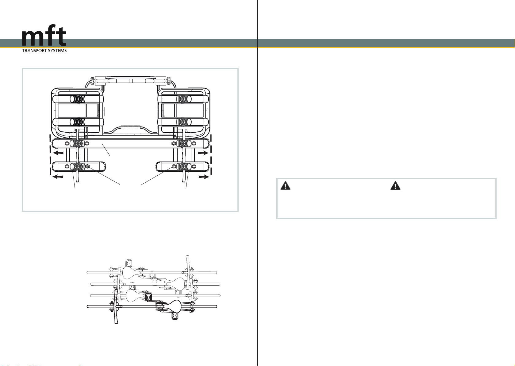
Transport von Fahrrädern
Auf keinen Fall darf die Ladung mit einer Folie
oder sonstigen Materialien abgedeckt werden,
dadadurchdasFahrverhaltenstarkbeeinflusst
werden kann.
Beachten Sie, dass alle Schlösser des Fahr-
radträgers sowie der Haltearme immer abge-
schlossen werden müssen.
Beim Transport der Fahrräder müssen alle
losen Teile (Luftpumpen, Kindersitze, Fahr-
radkörbe, Fahrradtaschen, Akkupacks usw.)
entfernt werden.
Sie könnten sich lösen und Sie oder nach-
folgende Verkehrsteilnehmer in Gefahr bringen.
Transport of bicycles
Never cover the load with a foil or other materi-
als, as it can affect the handling of your vehicle.
Ensure that all locks on the bicycle carrier and
the frame holders are always locked.
All loose parts (air pumps, water bottles, bas-
kets, child seats etc.) must be removed when
transporting the bicycles.
They can detach and put you or other road us-
ers in danger.
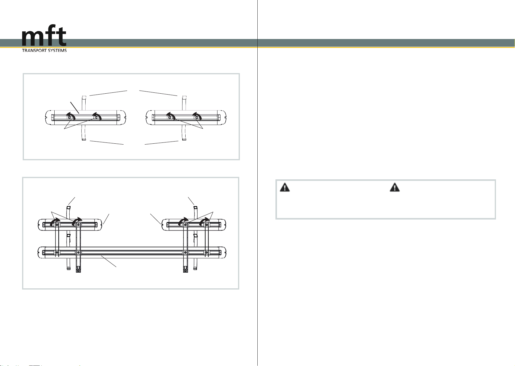
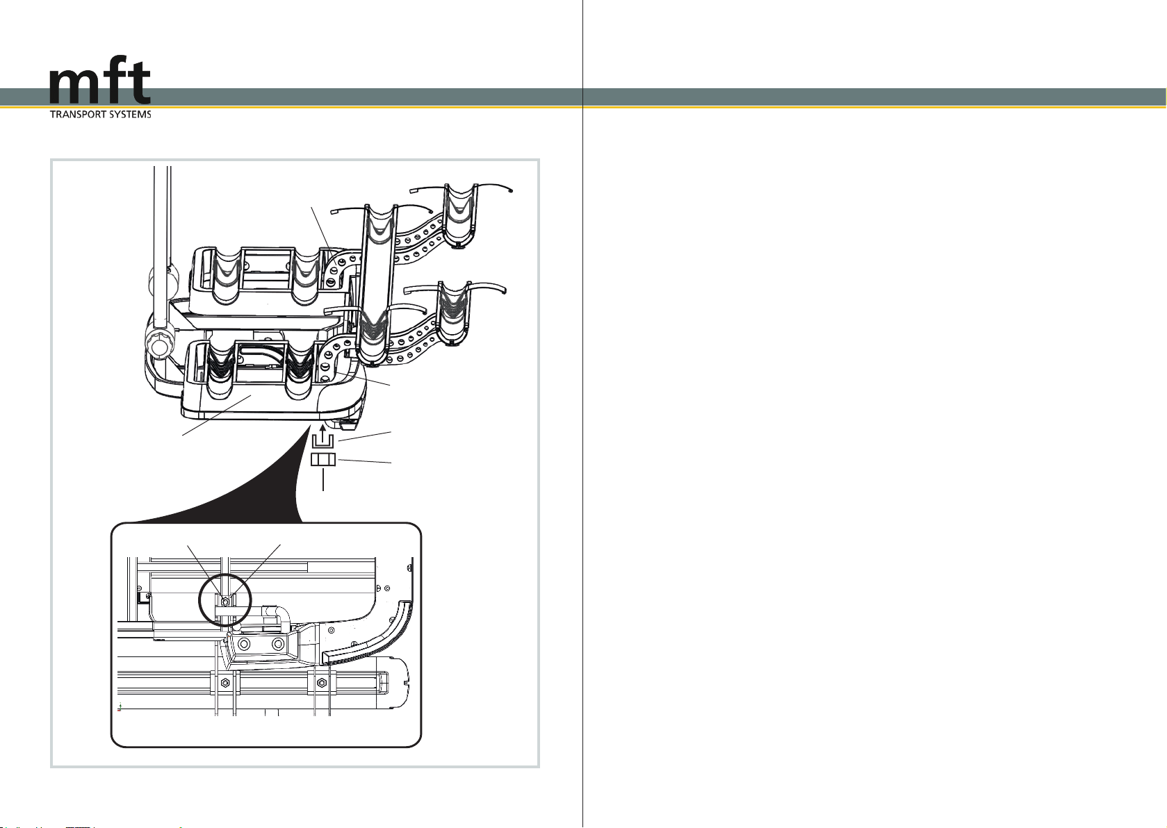
Montage
Sollten sich bei der Montage oder Bedienung
Fragen ergeben, wenden Sie sich bitte an eine
qualifizierte Fachwerkstatt. Änderungen von
technischen Details gegenüber Abbildungen
der Montageanleitung sind vorbehalten.
Jeder einzelne Arbeitsschritt sowie sämtliche
Sicherheitshinweise sind genau zu befolgen.
Bei sachgemäßer Montage und Handhabung
können keine Schäden an Fahrzeug und An-
hängekupplung auftreten.
Für Schäden, die durch Missachtung der Ar-
beitsreihenfolge und Sicherheitshinweise ent-
stehen, übernimmt die mft transport systems
GmbH keine Haftung.
Mounting
If you have any questions when assembling or
handling this product, please use a qualified
service center. Technical details are subject to
change and may differ from figures in the in
structions for assembling.
Each individual step of these instructions should
be followed exactly. If the bicycle carrier is in-
stalled and handled properly it will not damage
the vehicle and its trailer hitch.
mft transport systems GmbH is not liable for
damages caused by disregard of the assembly
sequence and safety instructions.
Vor Fahrtantritt
Vor jeder Fahrt ist die Funktion aller Leuchten
und der sichere Halt des BackPowers zu
überprüfen.
Nach der Erstmontage müssen alle Befesti-
gungselemente des BackPowers nach einer
Fahrtstrecke von ca. 15 km auf festen Sitz über-
prüft und ggf. nachjustiert werden.
Bei längeren Fahrten oder schlechter Wegstre-
cke die Prüfung regelmäßig wiederholen.
Before travelling
Before travelling check the lights if they are fully
functioning and if the BackPower is securely
fixed.
Afterthefirstinstallation,allfasteningelements
of the BackPower must be checked after a
test drive of approx. 15 km and be tightened if
necessary.
Repeat this test regularly, especially if the road
conditions are bad.
Sicherheitshinweise / Safety instructions
Sicherheitshinweise / Safety instructions
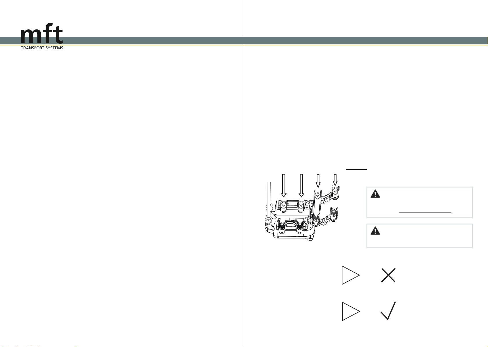
Maximale Belastung pro Radschiene
Maximum load per wheel rail
30 kg 30 kg 15 kg 12 kg
Die Gesamtbelastung darf dabei die maximale
Zuladung von 66 kg nicht überschreiten!
Vorsicht!
Do never exceed the maximum load of 66 kg!
Attention!
Beispiel / Example 1
Fahrrad / Bike 1 30 kg
Fahrrad / Bike 2 30 kg
Fahrrad / Bike 3 15 kg
Fahrrad / Bike 4 12 kg
Beispiel / Example 2
Fahrrad / Bike 1 25 kg
Fahrrad / Bike 2 20 kg
Fahrrad / Bike 3 11 kg
Fahrrad / Bike 4 10 kg
Falsch!
Wrong!
Richtig!
Correct!
87 kg
66 kg