latigid
DRAWN : IAC
DATE: 05/12/2009
CONTROLLED SYSTEMS LTD.
SWADLINCOTE, DERBYSHIRE. ENGLAND
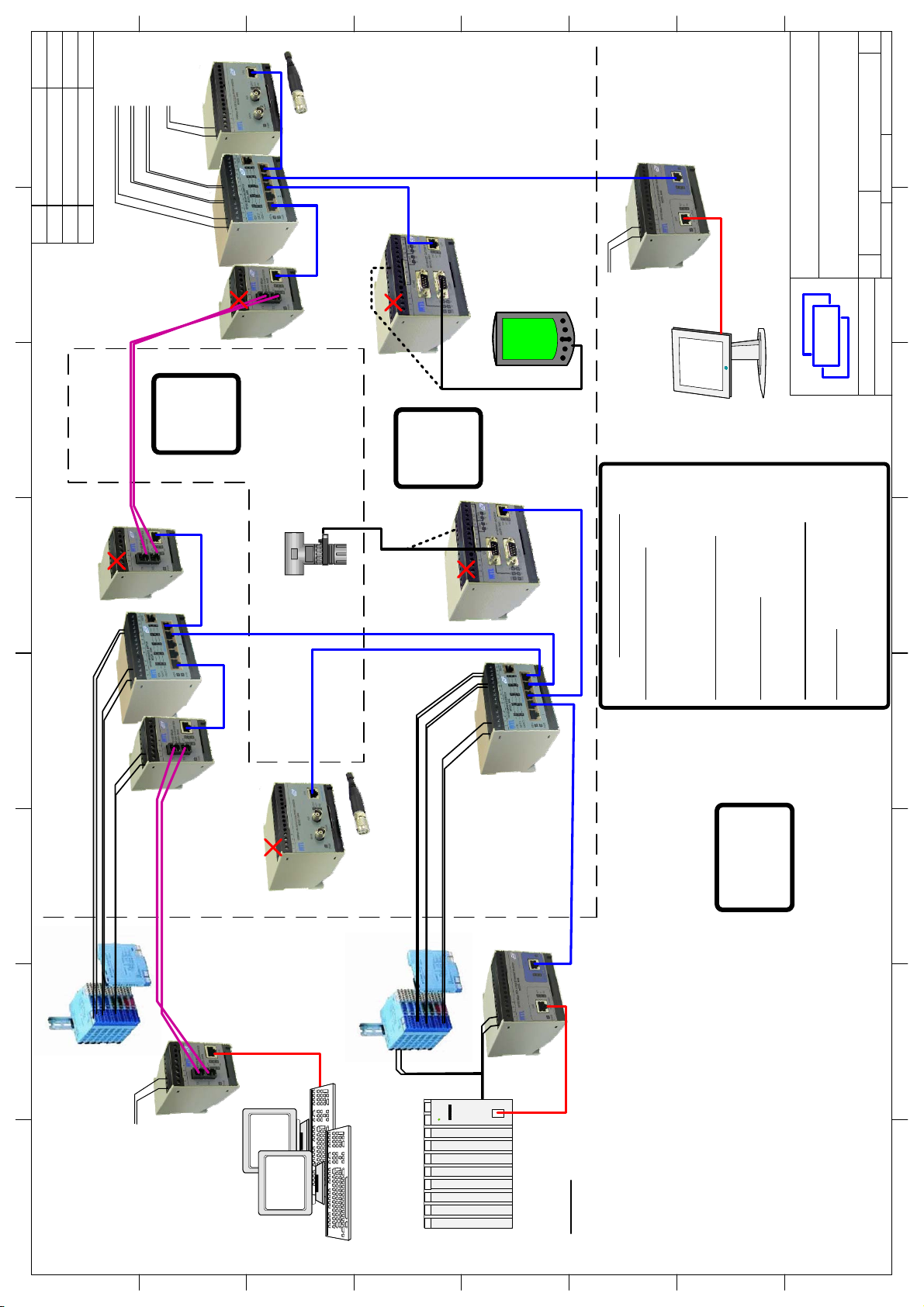
9400 Series Ethernet
System Drawing of
Typical Installation
SIZE DWG NO REV
A3 9400 System 4
SCALE SHEET 1OF2
CSL
SCALE
TITLE
H
G
F
E
D
C
B
A
87654321
H
G
F
E
D
C
B
A
87654321
20/08/2009
DATE
28/03/2007
REV DESCRIPTION
Updated for Issue2
Changes required for FM3
05/12/2009Added sheet 24
Fibre-Optic
Cable
Fibre-Optic
Cable
Cat5e/Cat6
I.S. Cable
Cat5e/Cat6
I.S. Cable
9465
Media
Converter
9466 5x Port
Switch
9461
Serial
Gateway
Unspecified Safe Area
Equipment
Unspecified Safe Area
Equipment
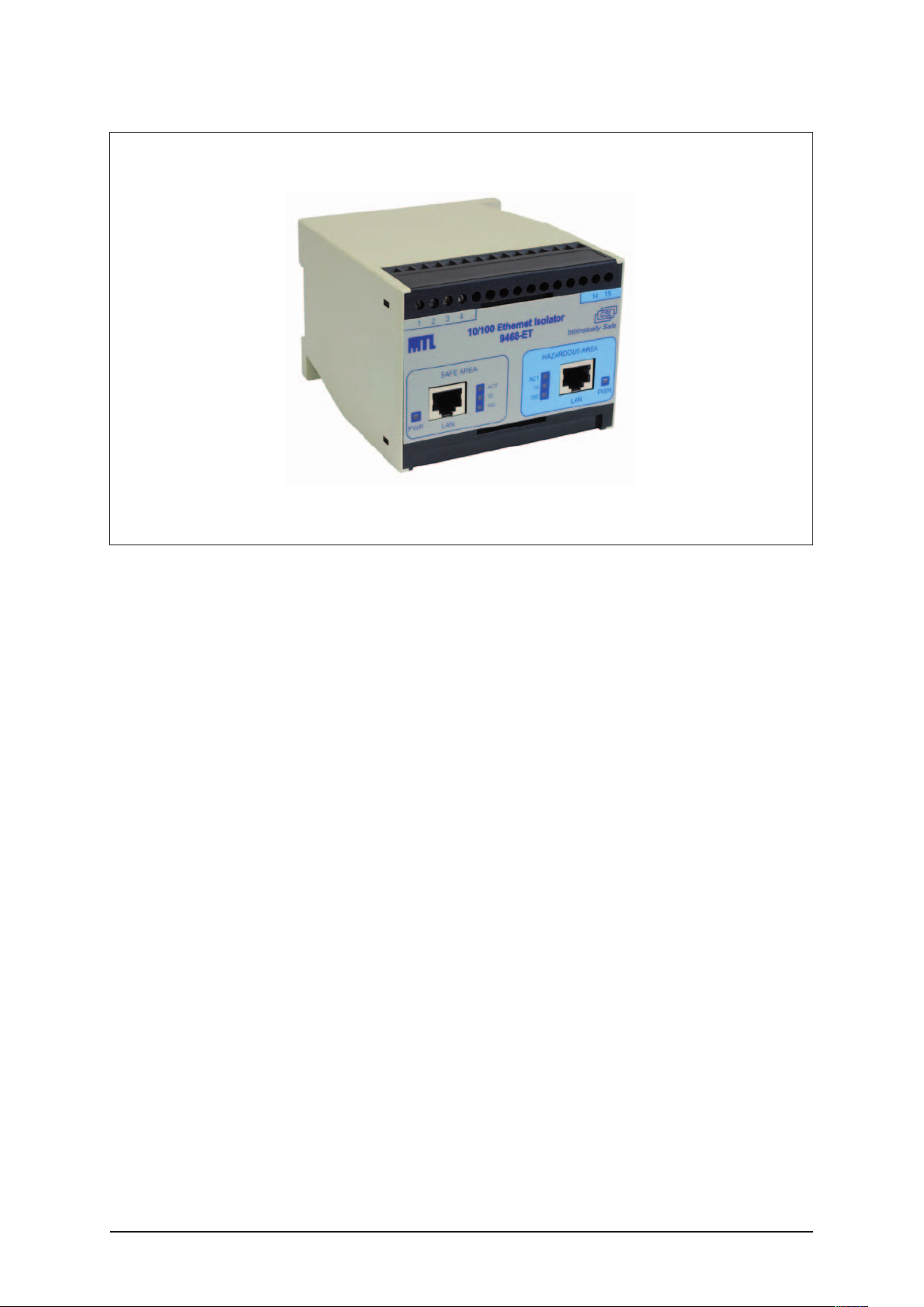
9468
Ethernet
Isolator
9468
Ethernet
Isolator
9461
Serial
Gateway
9466 5x Port
Switch
9465
Media
Converter
9465
Media
Converter
9466 5x Port
Switch
Certified or
Safe Area
Media
Converter
ZONE 1
Class I
Div 1
SAFE AREA
ZONE 0
Class I
Div 1
Unspecified Zone 0 Div 1
Equipment Entity
Parameters Matching
9461 - RS232/TTL.
RS485/422 Port
Unspecified Zone 1
Div 1 Equipment
Entity Parameters
Matching 9461 -
RS232/TTL. RS485/
422 Port
Power Supply Connections
12Vdc IS Power Supply (psu)
Any suitably certified IS power supply unit
for the intended gas/dust group and satisfying
the following requirements
Uo = 15.4V maximum (12.8V for 9469 module)
9461, 9465, 9466 Modules (app)
Ui = 15.4V
Ci=Li=0
9469 Modules (app)
Ui = 12.8V
Ci=Li=0
9468 Modules 24Vdc Supply Input
Um = 253Vac
Supply Cable
Cc (cable) <= Co (psu) - Ci (app)
Lc (cable) <= Lo (psu) - Li (app)
L/R(cable) <= Lo/Ro (psu)
12VDC
IS Power
Supply
9469 WLAN
AP/Bridge
PoEx Supply for Port 3 Device
Supply for 9466
PoEx for 9461
via Port 3
Supply for 9466
PoEx for 9465
via Port 5
Supply for 9465
(PoEx not used)
Supply for 9466
PoEx Supply for Port 5 Device
Supply for 9469
PoEx Supply for Port 1 Device
PoEx Supply for Port 3 Device
No PoEx
No PoEx
PoEx for 9465
via Port 1
No PoEx
No PoEx
PoEx for 9461
via Port 3
NO
POWER
NO
POWER
NO
POWER
NO
POWER
No PoEx
NO
POWER
PoEx Supply for Port 5 Device
PoEx for 9469
via Port 5
9469 WLAN
AP/Bridge
1. For ease of identification -Use BLUE coloured
Cat5e/6 cables in Zone 1 and 0 Hazardous
Areas, any other colour for Zone 2 or Safe Area
NOTES
2. 9465 Optical Radiation <= 5mW
9469 Radio Frequency Radiation <= 500mW
3. Fibre-Optic and BLUE I.S. Cat5e cables may run in
Zone 0, 1, 2 and Safe Area
4. 9400 Series Modules may be mounted in Zones 1, 2
or Safe Area (9468 may only be mounted in Safe Area)
5. 9400 Series Modules must be installed in a suitable
manner for the surrounding conditions, this may require
an additional protective enclosure in some areas.
6. PoEx (Power over Ethernet for Hazardous Areas) A
means of distributing IS power supplies to devices via
the Cat5 Ethernet cable as an alternative to a separate
power cable. Ensure only one power source is used
(PoEx or separate power cable)
7. Refer to User Manual for Connections and Installation
Instructions. See Certificate for Safety Description
12VDC
IS Power
Supply
12VDC IS
Power Supplies
24Vdc
Um = 253Vac
Um = 253Vac
Um = 253Vac
24Vdc
Um = 253Vac