MTS Systems SSI-1016J User manual

SSI-1016J
Specifications and Operation Manual
Warning: Product specifications and dimensions are subject to change
without prior notice.
MTS Sensors Technology Corporation
〒194-0211 737 Aihara-machi, Machida City, Tokyo
Tel:042-775-3838 Fax:042-775-5512
2014.04.18 Rev. 1.2

Revision History
2013/6/20 - First issued
2014/4/18 – p8 Connector information added

1.
Overview
SSI-1016J
The SSI-1016J unit converts serial SSI data output by Temposonics sensors
to parallel data. SSI (Synchronous Serial Interface) is a serial
communication protocol developed and widely used in Europe. By
converting the SSI signal to a parallel signal with the SSI-1016J,
Temposonics sensors can be used with a wider variety of controllers.
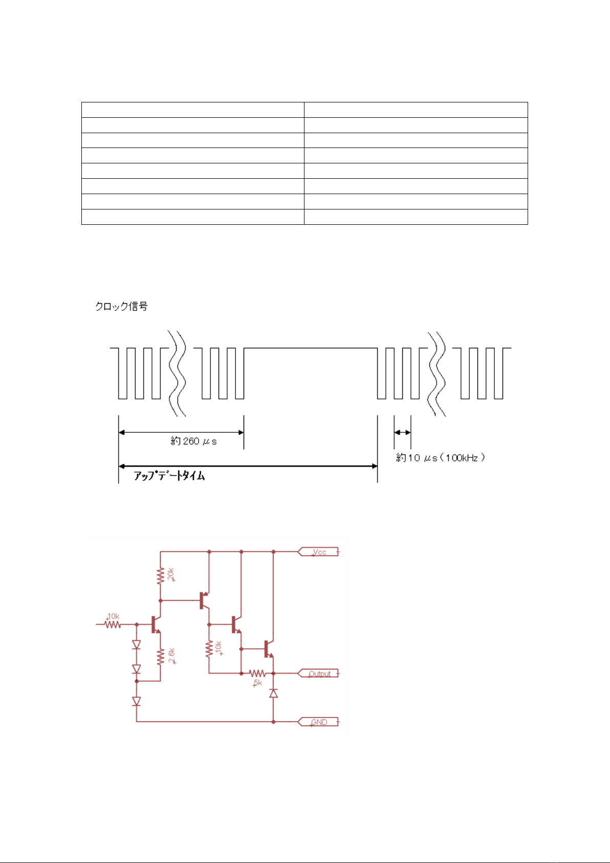
Furthermore, the SSI-1016J provides the necessary clock signal for SSI
communication.
SSI Communication Protocol
The SSI protocol is a serial transmission over a 4-wire, RS422-compliant
wiring configuration. A clock pulse train from a controller is used to gate
out sensor data. One bit of position data is transmitted to the controller for
each clock pulse received by the sensor. The maximum SSI clock baud rate
is dependent on the cable length and a minimum of 16μs dwell time is
required between each clock pulse train.
The output data is formatted in either binary or gray code with either 24, 25,
or 26 bits of data depending on Temposonics sensor settings. The most
significant bit (MSB) comes first and the least significant bit (LSB)
represents the resolution specified by sensor specifications. Each bit is
transmitted synchronously with the rising edge of each clock pulse.
SSI-1016J Operation
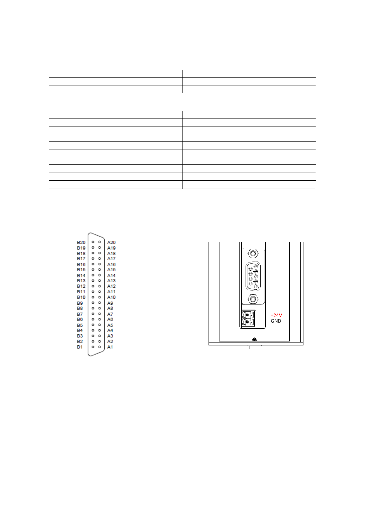
The SSI-1016J unit interfaces with 24, 25, and 26 bit SSI Temposonics
sensors with no adjustment necessary and outputs parallel data via an open
collector output. The SSI-1016J has two operation modes which are
selectable via the rotary switch mounted on the SSI-1016 front panel.
2) SSI Clock
3) SSI Data (input)
4) Parallel Data (output)
1) Read Command
Data Ready Signal
Temposonics
Sensor
SSI-1016J
Controller
Figure 1

A)
Automatic Mode
When set to automatic mode the SSI-1016J unit supplies a clock signal
based at a set interval (cycle time). This cycle time can be selected via
the rotary switch on the SSI-1016J front panel. Upon receiving this
clock signal the Temposonics sensor outputs its measurement data as
described above. This data is received by the SSI-1016J unit and
immediately output to the controller as parallel output.
Automatic mode constitutes steps 2→3→4shown in Figure 1 above.
※In automatic mode the Data Ready Signal is used to communicate the
timing for reading out the parallel output. See page 11 for details.
B)
Read Command Mode
When set to read command mode the SSI-1016J unit waits for a read
command from the controller. Once the read command is received, the
SSI-1016J unit supplies a single SSI clock signal to the Temposonics
sensor, which returns a single SSI data output. The SSI-1016J is
immediately output to the controller as parallel output.
Read command mode constitutes steps 1→2→3→4 shown in Figure 1
above.
2.
Specifications
Power Supply
Voltage
:
24VDC (+20%/-15%) Ripple: <1%PP
Current Consumption
:
160mA (typ.)
Communication Protocol
SSI ( Synchronous Serial Interface )
Output Data Format
Binary or gray code (sensor dependent)
Output Data Length
24, 25, or 26 bits (sensor dependent)
SSI Clock Baud Rate
100 kHz
Output
Transistor open collector with positive or negative
logic
Sustaining voltage
: +40VDC(max)
Sink Current
: 20mA(max)
Cycle Time
: 1ms, 5ms, 10ms, 50ms
Output Connector
FCN 40pin connector (Model #:FCN-365P040-AU)
Read Command Input
24V ( 16mA )
Photocoupler input
Falling and rising time (0 to 100%): <5μs
Sensor Connector
9pin D-Sub connector
Power Supply Connector
Bipolar screw terminal block
Wire size
:
0.2
~
1.25mm
2
( AWG 24
~
16 )
LED
Green LED:
Power On
Yellow LED: Not Used
Mount
DIN rail
(
35mm width
)
Operating Temperature
0
℃~
+70
℃
(No condensation)

Mode Select / Cycle Time Select Rotary Switch (mounted on SSI-1016J face)
Number
Mode / Cycle Time
0
Automatic Mode: 1ms (Default)
1
Automatic Mode: 5ms
2
Automatic Mode: 10ms
3
Automatic Mode: 50ms
4 – B
Reserved
C
Read Command Mode
D - F
Reserved
Note: Changes to mode or cycle time are not active until the SSI-1016J power has been
reset.
SSI-1016J SSI Clock Signal –
Figure 2
Parallel Output Equivalent Circuit –
Figure 3

3. Connection
Parallel Output FCN 40pin Connector –
Figure 4
Pin Number
Signal
24 Bit Sensor
25 Bit Sensor
26 Bit Sensor
A1
FG
FG
FG
A2
VCC
VCC
VCC
A3
Read Command+
Read Command+
Read Command+
A4
Read Command-
Read Command-
Read Command-
A5
Output Bit23 (MSB)
Output Bit24(MSB)
Output Bit23(MSB)
A6
Output Bit22
Output Bit23
Output Bit22
A7
Output Bit21
Output Bit22
Output Bit21
A8
Output Bit20
Output Bit21
Output Bit20
A9
Output Bit19
Output Bit20
Output Bit19
A10
Output Bit18
Output Bit19
Output Bit18
A11
Output Bit17
Output Bit18
Output Bit17
A12
Output Bit16
Output Bit17
Output Bit16
A13
Output Bit15
Output Bit16
Output Bit15
A14
Output Bit14
Output Bit15
Output Bit14
A15
Output Bit13
Output Bit14
Output Bit13
A16
Output Bit12
Output Bit13
Output Bit12
A17
Output Bit11
Output Bit12
Output Bit11
A18
Output Bit10
Output Bit11
Output Bit10
A19
Output Bit9
Output Bit10
Output Bit9
A20
Output Bit8
Output Bit9
Output Bit8
B1
GND
GND
GND
B2
GND
GND
GND
B3
GND
GND
GND
B4
GND
GND
GND
B5
Output Bit7
Output Bit8
Output Bit7
B6
Output Bit6
Output Bit7
Output Bit6
B7
Output Bit5
Output Bit6
Output Bit5
B8
Output Bit4
Output Bit5
Output Bit4
B9
Output Bit3
Output Bit4
Output Bit3
B10
Output Bit2
Output Bit3
Output Bit2
B11
Output Bit1
Output Bit2
Output Bit1
B12
Output Bit0(LSB)
Output Bit1
Output Bit0(LSB)
B13
Reserved
Output Bit0(LSB)
Output Alarm
B14
Reserved
Reserved
Output Parity
B15
Data Ready (Output)
Data Ready (Output)
Data Ready (Output)
B16
Reserved
Reserved
Reserved
B17
Reserved
Reserved
Reserved
B18
Reserved
Reserved
Reserved
B19
Reserved
Reserved
Reserved
B20
Reserved
Reserved
Reserved
Do not connect pins labeled “Reserved”
B1, B2, B3, and B4 are common
Warning:

Power Supply Connector (Bipolar screw terminal block) –
Figure 5
Terminal
Signal
1
+24VDC
2
GND
Sensor Connector (9pin D-Sub connector) –
Figure 5
Pin Number
Signal
1
+24VDC
2
Reserved
3
Reserved
4
Clock+
5
Clock-
6
GND
7
Reserved
8
Data+
※
9
Data-
※
※
Positive Logic → Pin8: Data+, Pin9: Data-
Negative Logic → Pin8: Data- Pin9: Data+
Figure 4
Figure 5
1
2
3
4
5
6
7
8
9
1
2

4.
Outline Dimensions
5.
Mating Connectors
The 40pin parallel output connector of the SSI-1016J unit is a Fujitsu
FCN-365P040-AU plug with M2.6 lock screws. Its mating connector is any
jack from the Fujitsu FCN-36xJ series and matching FCN-36 series housing.
The 9pin D-Sub sensor connector of the SSI-1016J unit is an Omron
XM3C-0922-112 plug with M2.6 lock screws. Its mating connector is any
Omron XM3 socket and hood or any other compatible 9pin D-sub connector.
※
Mating connectors are not included with the SSI-1016J unit and must be purchased
separately.
FCN 40pin connector
(Parallel Output)
Yellow LED
Red LED
Rotary Switch
9pin D-Sub (Male)
(Sensor Connector)
Bipolar Screw
Terminal
(Power Supply)
Earth Terminal

6.
Earth Terminal
Connect the SSI-1016J earth terminal to avoid unstable signals due to noise,
etc.
7.
Mounting and Dismounting
Mounting
Dismounting
①
②

8.
Data Ready Signal
When serial data received from the Temposonics sensor is ready to be output
as parallel data by the SSI-1016J unit, the SSI-1016J sends a Data Ready
Signal to the controller. The parallel output may be read while the Data
Ready Signal is low (output transistor is on). The parallel output is being
updated and may not be read while the Data Ready Signal is high (output
transistor is off).
When using Automatic Mode, the Data Ready Signal depends on the
cycletime setting.
See page 12 for information about Read Command Mode
Data Ready Signal and Cycle Time
Cycle Time [ms]
W1 [ms]
W2 [ms]
1
0.5
0.5
5
2.5
2.5
10
5
5
50
25
25

9.
Read Command Mode
When the Mode Select / Cycle Time Select Rotary Switch (mounted on
SSI-1016J face) is set to “C”, the SSI-1016J unit switches to Read Command
Mode. The Read Command + Signal looks like Figure 6 below. The
SSI-1016J unit outputs an SSI signal to the Temposonics sensor on the rising
edge of the Read Command Signal.
Ta: >100μs
Tb: >100μs
Tc: >1ms
Td: 500μs
Te: 10μs
Figure 6

The Data Ready Signal goes high for an interval of 500μs after the Read
Command Signal’s rising edge. When the Data Ready Signal is high
(output transistor is off), the SSI-1016J parallel output data is being updated.
The parallel output data can be read once the Data Ready Signal returns to
low.
10.
Handling Instructions
Use a shielded, twisted-pair cable to connect the SSI-1016J and
Temposonics sensor. A voltage drop in the power supply voltage may
occur due to the impedance of this cable. Check that the supply voltage
at the sensor is within the specifications (+24Vdc, +20%/-15%).
Check that the use environment is within the SSI-1016J operating
temperature (0℃-70℃). When mounting the SSI-1016J unit in a control
panel near other devices that produce heat, use a fan or other cooling
devices.
To avoid induced noise and other signal quality issues, place all
connections away from cables carrying heavy currents.
END
Read Command Signal Input Circuit
Figure 7
Table of contents
Popular Media Converter manuals by other brands

Bosch
Bosch VIP-X1600-XFM4A Quick installation guide

Extron electronics
Extron electronics DDS 402 Specification sheet

Digigram
Digigram PYKO-in user manual

StarTech.com
StarTech.com VGA2HDMIPRO instruction manual

Bose
Bose FREESPACE 4400 Service manual

Colorado Video
Colorado Video 641 series instruction manual