Important Regulatory and Safety Notices to Service Personnel
Before using this product and nay associated equipment, refer to the “Important Safety
Instructions” listed below to avoid personnel injury and to prevent product damage.
Product may require specific equipment, and/or installation procedures to be carried out to satisfy
certain regulatory compliance requirements. Notices have been included in this publication to call
attention to these specific requirements.
Symbol Meanings
Important Safety Instructions
This symbol on the equipment refers you to important operating and maintenance (servicing)
instructions within the Product Manual Documentation. Failure to heed this information may
present a major risk of damage to persons or equipment.
Warning — The symbol with the word “Warning” within the equipment manual indicates a
potentially hazardous situation, which, if not avoided, could result in death or serious injury.
Caution — The symbol with the word “Caution” within the equipment manual indicates a
potentially hazardous situation, which, if not avoided, may result in minor or moderate injury. It
may also be used to alert against unsafe practices.
Notice — The symbol with the word “Notice” within the equipment manual indicates a
potentially hazardous situation, which, if not avoided, may result in major or minor equipment
damage or a situation which could place the equipment in a non-compliant operating state.
ESD Susceptibility — This symbol is used to alert the user that an electrical or electronic
device or assembly is susceptible to damage from an ESD event.
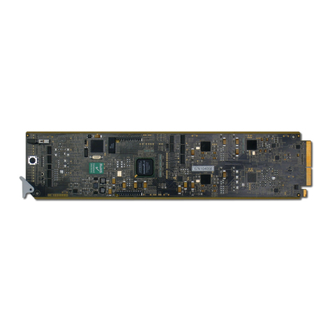
Caution — This product is intended to be a component product of the DFR-8300 series
frame. Refer to the DFR-8300 Series Frame User Manual for important safety instructions
regarding the proper installation and safe operation of the frame as well as its component
products.
Warning — Certain parts of this equipment namely the power supply area still present a
safety hazard, with the power switch in the OFF position. To avoid electrical shock, disconnect
all A/C power cords from the chassis’ rear appliance connectors before servicing this area.
Warning — Service barriers within this product are intended to protect the operator and
service personnel from hazardous voltages. For continued safety, replace all barriers after any
servicing.
This product contains safety critical parts, which if incorrectly replaced may present a risk of
fire or electrical shock. Components contained with the product’s power supplies and power
supply area, are not intended to be customer serviced and should be returned to the factory for
repair. To reduce the risk of fire, replacement fuses must be the same time and rating. Only use
attachments/accessories specified by the manufacturer.
