MuginUAV MUGIN-2 2930 VTOL User manual

MUGIN VTOL UAV
(Electric Setup)
BUILD GUIDE V1
FOR
MUGIN-2 2930 VTOL MUGIN-2 PRO 2930 VTOL
MUGIN-3 PRO 3000 VTOL MUGIN-4 PRO 4000 VTOL
Copyright © 2019 Mugin Tech Ltd.

1
Safety & Warning
Thank you for your purchase of the Mugin VTOL. This product is a sensitive item and illegal use is
strictly prohibited. Mugin UAV is not responsible for any consequences arising out of illegal use, or
third party responsibility incurred with the product use.
For safety, please read the manual before moving forward with building and operating the product.
Please pay attention to all local laws, flight zone restrictions, and ensure the personnel operating
the aircraft have proper licensing and approval for flight plans.
Overview
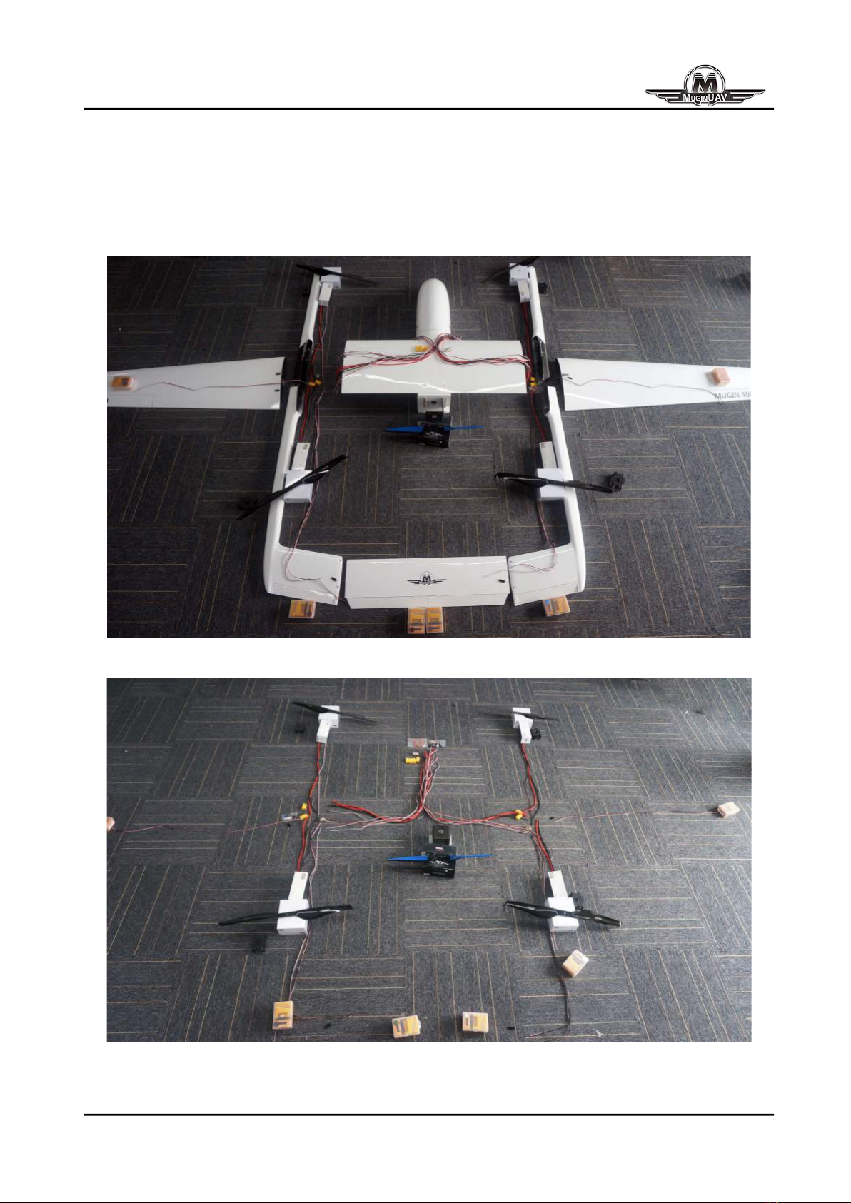
The Mugin VTOL is a hybrid configuration aircraft with fixed wing and multi-copter flight options.
This gives the aircraft the ability to take off and land vertically, it also has the ability to transition to
forward flight like a fixed wing. This hybrid configuration combines the advantages of VTOL and
high speed, long endurance flights of a fixed wing.

2
Scope of Delivery: Before assembling and building your aircraft, please familiarize yourself with the
below listed parts.
No. Part Picture No. Part Picture
A1 Left front
boom E Center Wing
A2 Left rear boom F1 Left landing skid
A3 Right front
boom F2 Right landing
skid
A4 Right rear
boom F3 Forward landing
arch
B1 Left wing F4 Rear landing
arch
B2 Right wing G1 Main Forward
Carbon Spar
C Rear elevator G2 Rear Carbon
Spar
D Fuselage

3
Power System
The Mugin UAV is DIY in nature and it’s up to the user to decide the components that they want to
use. Below is a power system that we have selected and is available for optional purchase.
No. Description Picture
1 Savox SC-1251MG Low Profile Digital Servo x 6
2 T-motor MN805-S KV170 (VTOL Motors) x 4
3 T-motor Flame 80A HV ESC x 4

4
4 Dualsky XM6352EA 380KV (Forward Motor) x 1
5 T-motor Flame 100A HV ESC x 1
6 Motor Mount for Forward Thrust Motor
7 Motor Mount for VTOL Thrust Motors
8 Main Power Wires for Electric Motors
9 Main Power Wires for PDB
10 22A Silicone power lines
11 Servo Extension Wires
12 Servo extension connectors
13 D-Sub connectors 2x 15pin, 1x 24pin

5
14 Various Heat Shrink Tubing
15 XT90 Multi-pack for power connections
16 Power Distribution Board
17 50.4v Voltage Regulator to 6v
18 Falcon PAE 24″Propeller (Pairs) x 2
19 Falcon C2E 21″Propeller x 1
* Due to the stock availability, the listed items are subject to change without prior notice.

6
Power System Installation
Mugin airframes are very DIY in nature. Before attempting to build, please make certain you and
your team have the required experience and skill set that is needed in order to build a model such
as this.
Pictured above is a rough layout for the optional power Package.

7
Servo Installation
1. Beginning with servo installation in the elevator. Take two Savox servos and install in the
cutouts. Before attempting to install control horns servos should be tested and centered to
prepare for proper control placement.

9
2. When installing servos for the Rudder control make certain to install proper length extension
wire first. You will need two sets of extension wire. One is for the rudder servo and extension line
will come out at elevator connection.
Picture 1 shows the the Rudder Servo (A) and the extension wire for Elevator Servo (B).
Picture 2 shows the extension wire connected. Remember to give yourself enough wire length to
exit the large opening in the center of the boom.

10
Picture 3 shows the layout of the wiring before servo installation.
3. Aileron Servo Installation: The aileron servo installation is a relatively easy process. If using
D-Sub connectors remember proper wiring placement to avoid reverse polarity issues.

11
Once again, remembering the wiring sequence of the D-Sub connectors to avoid reverse polarity
issues. The D-Sub connectors can be attached using aluminum rivets.(2A).

12
A few key points to remember:
When installing the servos remember to properly center them with a servo tester before installing
the control horns. The soldering between the servos and wire extensions should be shiny and firm.
Remember to place the heat shrink on the wires before soldering. If using D-Sub connectors
remember proper wire mapping to avoid reverse polarity.
Motor Installation
Build tip: The motor mount has a small angular offset. When installing, make certain the motors
lean outward and not inward towards the plane.
Aluminum rivets and floating lock nuts will be used for the motor mounts. At the time of releasing
the manual, this cutting process will no longer be required. If you have purchased a Mugin in the
The process is straight forward and can use the following 5 steps to complete the process.

14
Picture 6(A1): Connect the motor to ESC (A1),ESCs to power extension wires, install extension
wires for servo.(A2)

15
Before Installing motor on the boom, it’s good practice to test the motor to make certain all
connections are verified to be working properly. (A3)
When installing the ESC everyone has their own methods. The one we use is to run the double
sided tape down the bottom facing edge of the ESC and use blue foam on the outside surfaces to
help with vibrations. Please refer to B1 and B2.

16
After completing the installation of the ESC, the Motor is now free to be mounted. C1 and C2

17
With the VTOL motor complete, you will have to complete the same steps for the other three
booms.
Center Wing
The center wing wiring needs to be completed with caution and a clear understanding of the
wiring. It helps to label each set of wires for each component to not get confused. By this time you
will be setting up the wiring for four motors, four ESCs and six servos. Having a clear plan at this
point is a must but if you follow the steps above, it won't be too complicated.

18
Clean Wiring
To make things easier it also helps to run sleeves over each group of wires. At this point you will
have 5 sets of sleeved wiring.
1: Main Power Lead for Power Distribution Board.
2: Power Leads out to Left VTOL ESCs (Front and Rear Motors)
3: Power Leads out to Right VTOL ESCs (Front and Rear Motors)
4: D-Sub connectors for Left Side signal, GND, power lines of servos and ESCs.
5: D-Sub connectors for Right Side signal, GND, power lines of servos and ESCs.
Power Distribution Seat
With the main wiring harness complete, special thought needs to go into where to place the
power distribution board. With this particular model we are choosing to go with the interior of the
center wing. Some clients mount it in the fuselage. You are free to do as you please. We are going
with this method on this one by cutting out a slot to mount it to the interior of the center wing.

19
Once the slot is cut out we’ve routed the wires through the center of the wing and now have the
main wiring harness on the interior.
This manual suits for next models
3
Table of contents
Other MuginUAV Toy manuals
Popular Toy manuals by other brands

Eduard
Eduard 53 160 manual

Eduard
Eduard SH-60B S.A. Assembly instructions

Eduard
Eduard SAM-6 AA missile Assembly instructions

THE WORLD MODELS
THE WORLD MODELS Jeff Troy's TAMEcat EP ARF instruction manual

Mega Bloks
Mega Bloks nickelodeon TEENAGE MUTANT NINJA TURTLES OUT OF THE... manual

REVELL
REVELL BAe Harrier GR.Mk.7 Assembly manual

GREAT PLANES
GREAT PLANES Giant U-Can-Do 3D instruction manual

Eduard
Eduard MiG-19S Farmer C quick start guide

KMP
KMP T-28 Trojan instruction manual

Desktop Locomotive Works
Desktop Locomotive Works PKB V1 quick start guide

MTHTrains
MTHTrains Premier 20-91219 quick start guide

Marklin Digital
Marklin Digital Central Station 60216 manual