MuginUAV EV350 User manual

EV350 Quick Installation Guide
V1.0
Copyright © Mugin Limited, 2023 - https://www.muginuav.com

Table of Contents
Safety Precautions....................................................................................................................................................................................................... 3
Product Features......................................................................................................................................................................................................... 3
Transportation............................................................................................................................................................................................................. 3
Specifications...............................................................................................................................................................................................................4
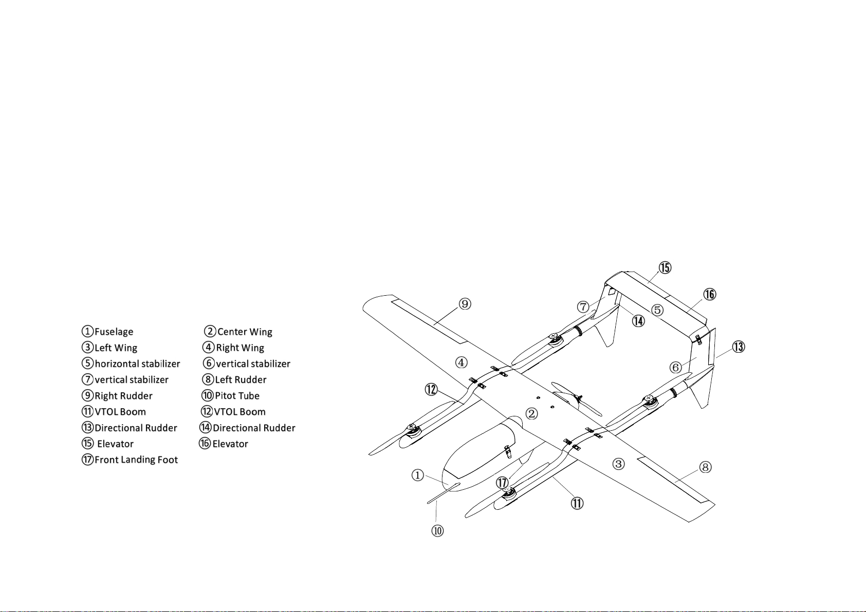
Structure......................................................................................................................................................................................................................5
Contents of the Box..................................................................................................................................................................................................... 6
List of Parts........................................................................................................................................................................................................... 6
List of Contents.....................................................................................................................................................................................................7
Accessories........................................................................................................................................................................................................... 8
Structural Installation Instruction................................................................................................................................................................................9
Preparation of Equipment.................................................................................................................................................................................... 9
Body Platform Installation....................................................................................................................................................................................9
1. Installation of Center Wing........................................................................................................................................................................9
2. Installation of Carbon Tubes....................................................................................................................................................................10
3. Installation of Booms. ..............................................................................................................................................................................11
4. Installation of vertical stabilizers............................................................................................................................................................. 12
5. The connection of horizontal stabilizer and vertical stabilizers...............................................................................................................13
6. Installation of left wing and right wing. ...................................................................................................................................................14
7. Installation of VTOL propellers................................................................................................................................................................ 15
8. Installation of Pusher Propeller............................................................................................................................................................... 16
9. Installation of Pitot Tube......................................................................................................................................................................... 17
10. Placement of batteries.......................................................................................................................................................................... 17
Field Flight................................................................................................................................................................................................................. 18
Pre-flight Check.................................................................................................................................................................................................. 18
Take-off...............................................................................................................................................................................................................19
Return & Landing................................................................................................................................................................................................19

— 3 —
Safety Precautions
Please strictly follow the installation guide for the assembly, adjustment, and flight of the aircraft. Improper operation may cause product
damage or even serious personal injury.
Product Features
EV350 is a new electric-powered VTOL drone with a wingspan of 3500mm. It features a quick-disassembly design that allows for assembly and
disassembly in just 5 minutes. The aircraft's belly fin landing gear is aerodynamically designed to reduce wind resistance. The unique three
landing feet design saves space and weight, and its stability is ensured by the triangular structure during takeoff and landing.
EV350 supports one-click takeoff, landing, hovering, circling, altitude hold, and can create 8 user-defined routes, each with up to 800
waypoints and the ability to execute photo-taking tasks at regular intervals. The high-definition gimbal camera (optional) on the aircraft
transmits real-time video to the ground station for users to monitor ground situations in real-time. Flight data is also transmitted back to the
ground station through a data link for monitoring the aircraft's flight status. After completing the task, the aircraft will automatically return
home.
Transportation
During the transportation, the drone body should be held or the root of the wing should be lifted. Lifting the wing tip or tail is not allowed, and
the aircraft should be handled with care. Please do not scratch, knock or collide the drone body. It is also not allowed to arbitrarily move the
aileron or elevator.

— 4 —
Specifications
Wingspan 3500mm Flight Endurance (w/o Payload) 3 Hours
Length 1860mm Flight Range 180km
Empty Weight 7kg Grade of Wind Resistance Cruise Mode Grade 5, VTOL Grade7
Maximum Take-off Weight 22kg Flight Altitude 5000 meters
Payload 3kg Flight Radius 80km
Propulsion System Full Electric GPS Accuracy <0.1m
Cruise Speed 75km/h Take-off & Landing VTOL
Maximum Speed 108km/h Control Method Automatic, Semi-automatic, Manual
Stall Speed 55km/h Auto Protection Automatic Return, Nearest Landing

— 5 —
Structure
The EV350 is primarily composed of a fuselage, a center wing, a left wing, a right wing, a horizontal stabilizer, two vertical stabilizers and two
VTOL booms.
Fuselage: It carries the battery, mission equipment, control system, and the tail propulsion system, and it also serves as the mounting base for
the wing components.
Wings: They are the collection of systems that generate lift for the aircraft, and the trailing edge of the wings has operable control surfaces.
Vertical stabilizers: They control the pitch direction of the aircraft.
VTOL Booms: They serve as fixed supports for the motors and are detachable, including the electronic speed controllers (ESC), rotor arm, rotor
ESCs, motors, and propellers.

— 6 —
Contents of the Box
List of Parts

—
7
—
List of Contents
NO. Description QT
Y
1 Fuselage 1
2 Center Wing 1
3 Left Wing 1
4 Right Wing 1
5 Horizontal Stabilizer 1
6 Vertical Stabilizer 2
7 Carbon Tube 2
8 VTOL Boom 2
9 CG Board 2
10 Accessories (Optional) 1
11 Propulsion System (Optional) 1
12 EV350 Quick Installation Guide 1
13 Installation Manual 1

—
8
—
Accessories

—
9
—
Structural Installation Instruction
Preparation of Equipment
Body Platform Installation
1. Installation of Center Wing.
Connect the wiring between center wing and fuselage, then insert the center wing into the corresponding position of fuselage, and tighten the
screws by hand to secure the center wing.
Insert the center wing into
the corresponding position of
fuselage.

—
10
—
2. Installation of Carbon Tubes.
Insert two carbon tubes into the carbon tube holes of the drone's mid-wing respectively, and the reserved length of the two carbon tubes must
be consistent.

—
11
—
3. Installation of Booms.
Install the left boom into the carbon tube and attach it to the center wing, then lock the quick-release buckle. Install the right boom in the
same way.
Please correctly
identify the left
and right booms.

—
12
—
4. Installation of vertical stabilizers
After tightening the wiring interface between the vertical stabilizer and the boom, the flange ring can be tightened clockwise to complete the
installation of the boom. Install the other vertical stabilizer in the same way and tighten the flange nut.

—
13
—
5. The connection of horizontal stabilizer and vertical stabilizers.
Connect the connector plug between the horizontal stabilizer and the vertical stabilizer, ensuring it is fully inserted and then lock it with the
latch to complete the installation of the horizontal and vertical stabilizers.

—
14
—
6. Installation of left wing and right wing.
Insert the carbon tube hole on the left wing into the corresponding carbon tube on the left strut, and install it by connecting it to the boom.
After tightening the electrical connectors between the wing and the boom, lock it with a latch to complete the installation of the left wing.
Repeat the same process for the right wing.
Note: After assembly, check whether the quick-release latch connecting the left and right wings springs up normally.

—
15
—
7. Installation of VTOL propellers.
Put the washer into the motor slot and secure the screw tightly with your hand after installing the propeller. After installation, check whether
the propeller installation direction is correct.
Note:
1. Identify the front and back sides of the propeller, do not install it backwards, and the two diagonally opposite blades are the same.
2. Ensure that the propeller rotates in the correct direction.

—
16
—
8. Installation of Pusher Propeller.
Install the pusher propeller onto the motor shaft, making sure that the blades are not installed backwards. Place the washer and nut, and
tighten the nut with a hex socket wrench. Check whether the propeller direction is correct.
Note: Ensure that the propeller rotates in the correct direction.

—
17
—
9. Installation of Pitot Tube
Screw the pitot tube into the corresponding hole on the fuselage, cover it with the canopy, and lock it with the latch.
10. Placement of batteries.
Check the battery voltage before placing them. Remove the battery compartment cover at the front end of the fuselage, then plug the
batteries into the drone battery port and place them in the battery compartment. Finally, cover the battery compartment with the cover.

—
18
—
Field Flight
Pre-flight Check
1. Check if all aircraft components are securely installed and if screws are tightened;
2. Check if the tower buckle is fastened and if the circuit connection is normal;
3. Power on the ground station radio and connect to the computer;
4. After the connection is completed, the ground station operator observes whether the voltage, current, and attitude are normal;
5. Prepare for airspeed calibration; (For the first flight, calibration is required. For subsequent flights, only check if it is normal. To calibrate
the airspeed, the pitot tube needs to be placed in a windless state, such as covering it with a bottle);
6. Click to execute the action, and then confirm the completion of the calibration;
7. Remove the bottle after calibration is complete;
8. Check if the airspeed is normal; Firmly cover the pitot tube with your fingers. There will be changes in the ground station airspeed
display (7-8), and there will be a significant change in airspeed when blowing into the tube.
9. Check the rudder feedback; Switch the remote control mode switch to the FBWA mode, and the flight personnel operate the remote
control to see if the aircraft's rudder response is normal. When raising the tail horizontal stabilizer, the servo rudder will provide
feedback, and the ground station will display the aircraft in a pitch-down state. When raising the left wing, the servo rudder will provide
feedback, and the ground station will display the aircraft in a left-leaning state.
10. Prepare to check the motor direction; Switch the remote control mode switch to QSTABIL;
11. Unlock the aircraft; Slightly push the remote control throttle to see if the motor direction and feedback are correct. The flight personnel
manually fly the aircraft with the remote control to test if the VTOL flight status of the aircraft is normal. The ground operation
personnel observe if the voltage, current, and status are normal.
12. Plan the route; Drag the takeoff point, landing point, and H point to the location of the aircraft. The takeoff and landing directions are
both facing the wind. Check the waypoint radius, hover radius, and default height.

—
19
—
Take-off
The flight process of a drone is to complete the flight of preset waypoints in self-control mode. If necessary, the waypoints can be changed
during the flight to alter the set flight plan until the mission is completed and the drone returns.
Return & Landing
After the drone completes its mission and returns to the takeoff point, the operator should switch to manual control mode based on the
ground monitoring data when the drone is above the takeoff point and the operator can clearly see its attitude, and guide the drone to land
safely.
Other manuals for EV350
1
Table of contents
Other MuginUAV Toy manuals
Popular Toy manuals by other brands

marklin
marklin 37439 instruction manual

Durafly
Durafly Excalibur V2 instruction manual

Chicco
Chicco SCUDERIA FERRARI SF-90 RIDE-ON instruction manual

MTHTrains
MTHTrains RAIL KING BALDWIN AS616 DIESEL ENGINE Operator's manual

Lionel
Lionel Fire Set owner's manual

Eduard
Eduard Kittyhawk Mk.Ia landing flaps manual

Mattel
Mattel ULTIMATE ENTRANCESTAGE instructions

Horizon Hobby
Horizon Hobby Ultimate 3D instruction manual

WowWee
WowWee Lite Sprites user manual

KidKraft
KidKraft 53287 Assembly instructions

Carrera
Carrera 30153 NASCAR Daytona 500 Assembly and operating instructions

RACE TRACK SCENICS
RACE TRACK SCENICS 10D2 Assembly instructions