Table of Contents
Introductions
3
Introductions
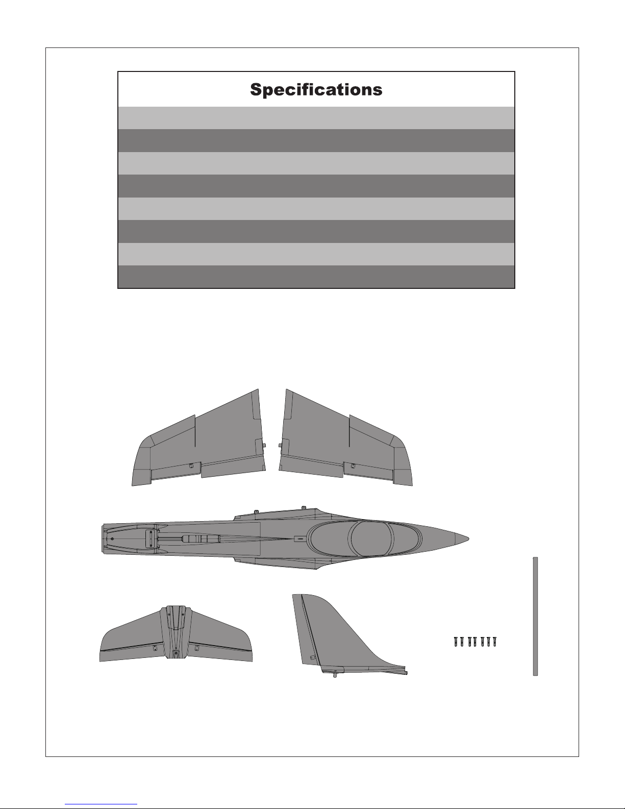
Contents of Kit
Model Assembly
Battery and radio installation
Important ESC and model information
The transmitter and model setup
Check the control throws
Control Horn and Servo Arm Settings
Center of Gravity(CG)
Before flying the model
Flying Course
Trouble shooting
Spare parts list content
ESC instruction
··························································································································3
························································································································4
······················································································································5
·····································································································8
··························································································9
······························································································9
········································································································10
·························································································11
·············································································································12
············································································································13
·······················································································································14
····················································································································15
··········································································································16
······················································································································17
The fantastic 70mm EDF Avanti is coming! Avanti is a mutual-developed airplane made by FMS team from
China and Sebart Team from Italy. The original design and authorization are from Sebart, with the additional
FMS advanced production concept, it is finally being a promised finest work.
Utilizing many new concepts and technologies from existing planes, this highly anticipated Avanti has the
inherent ability to offer a rip-roaring flight.
We have optimized the airframe structure markedly to make your time in getting ready for flight quick and
easy. The assembly is very straightforward: 7 screws and a carbon fiber wing spar and you are finished. The
Avanti features the latest FMS locked-rotor mode E-retract with overcurrent protection, the CNC-processed
shock-absorbed front and rear metal landing gear set (Worm Dia. 8mm), a 50mm diameter front wheel and
55mm rear wheels. These are excellent for taking off and landing on both paved and grass surface airfields.
The power system, which provides tremendous thrust and speed, utilizes our new and improved 70mm
12-blade EDF V2, KV1850 motor system. This brawny system, when coupled with a 6S battery, provides a
resonating turbine engine sound. Moreover, to meet different needs, we have optional KV2750 motor
system with Sebart design color scheme, which coupled with 4S battery for the customers who pay more
attention on aerobatic flight.
Key Features:
1. Powerful motor with the latest 70mm 12-blade EDF
2. With Predator 70A ESC, 6S power system ensures a record speed of more than 130km/h, 4S power
system ensures excellent aerobatic flight
3. The latest Metal CNC locked-rotor mode E-retract with overcurrent protection
4. No glue required, screw-together construction
5. Multi-connector for one-step installation
6. Metal digital servos for excellent controlling capacity
7. Button Type canopy hatch
8. Large battery compartment
9. Pre-installed, newly designed ball link style control horns for more throw.
10. 50mm front wheel and 55mm rear wheels