Muirhead 16936 User manual

PRODUCT MANUAL
COMPACT FIRE SYSTEM STATUS PANEL
Part No. 16936

2| 16
M1374.docx | Rev 1.0 | Modified on 31/03/2022 | © Remote Control Technologies Pty Ltd
LEGAL NOTICE
1. You acknowledge that this document is protected under copyright law and Remote Control Technologies Pty Ltd or its related bodies
corporate (‘RCT’) owns the copyright in this document or otherwise have permission or licence from the relevant owner to use certain
specific works.
2. You must not make any changes, amendments, variations, alterations, or modifications to the document.
3. You must not reproduce this document in any form or by any means, or to make copies of this document without RCT’s prior written
consent.
4. The contents in this document constitute confidential information of RCT. You must not circulate, distribute, or otherwise allow the
document to be available in the public domain, or to disclose or share the document with any third party, without RCT’s prior written
consent.
5. RCT provides the document to you on an ‘as is’basis. RCT is not required to provide any updates to this version of the document.
RCT may make any change, amendment, or modification to the contents in this document without notice to you.
6. RCT takes a best endeavour basis to ensure that the contents in this document are accurate, complete, and reliable. RCT does not
warrant that the document will continue to be reliable, relevant, accurate or complete due to RCT’s continuous efforts in product
development, innovation, and technology.
7. Any trademarks used in this document belongs to RCT or is used under a licence. The trademarks are not to be used for any
purposes, without RCT’s prior written consent.
8. Any illustrations used in this document are for illustration purposes only. Illustrations are intended as aids to facilitate your
understanding of the subject matter or issue.
9. RCT disclaims all liability, loss or damage that you suffer as a result of your reliance on this document.
10. If this document has been translated into a language other than English, the English version will be used for the purposes of
interpreting the meaning of the document.
11. By your conduct of using or reading this document, you agree to and accept the terms in this notice.

M1374.docx | Rev 1.0 | Modified on 31/03/2022 | © Remote Control Technologies Pty Ltd
3| 16
Contents
General Safety Warnings 4
Personal Safety 4
Machine 4
Product 4
Product Overview 5
Features and Functions 5
Operation and Use 6
Installation Guide 7
Wiring Connections 7
Diagrams 8
- External Wiring Diagram (750e) 8
Calibration 9
Calibration (CAL) Mode 9
No Extension Mode 9
Service Information 10
Service Schedule 10
Service Procedure 10
Parts List 10
Technical Specifications 11
Compliance and Standards 11
Troubleshooting 12
Glossary 13
Warranty 14
Revision History 15

4| 16
M1374.docx | Rev 1.0 | Modified on 31/03/2022 | © Remote Control Technologies Pty Ltd
Table of Figures
Figure 1 Muirhead®Light Vehicle Fire System Status panel, part number 16936........................................... 5
Figure 2 Drawing 750e –External wiring diagram ........................................................................................... 8
Figure 3 Flowchart FC0107 –Troubleshooting flowchart............................................................................... 12
General Safety Warnings
Personal Safety
■Everyone is responsible for safety.
■The installer/service personnel should be trained and authorized to complete the required work.
■Ensure that the machine is safely isolated during installation and testing to protect all personnel.
■Complete all required risk assessments and job safety analysis (JSA) before commencing work.
■Observe all site specific and machine OEM procedures regarding the following:
–working at heights
–working in heat
–working in confined spaces
–all other site specific occupational health and safety (OH&S) procedures
Machine
■Carry out all pre-start operations as per site and machine OEM procedures.
■Ensure the machine is safely isolated during installation and testing to protect the machine and other
equipment in the area.
■Do not operate any machine with a known fault and report all findings to the supervisor in writing.
■Test and operate machine as per machine OEM and site procedures.
■Read and understand machine and site specific operational and testing instructions.
Product
Before applying power to the equipment, the user/repairer/ installer must read all product instructions. If in
doubt, seek assistance.
■Ensure electrical connections are made as per RCT’s recommendations. Test circuits prior to connecting
power to any component.
■The equipment contains no user serviceable parts inside. Return the unit to RCT for repairs.
■Retain product and installation instructions for future use.
■Ensure that RCT’s recommended service procedures are included in the machine’s service routine.
■Observe all machine, site and RCT product warnings.
■Follow all machine, site and RCT product operating procedures at all times.
The application of safety should not be limited to the above recommendations.

M1374.docx | Rev 1.0 | Modified on 31/03/2022 | © Remote Control Technologies Pty Ltd
5| 16
Product Overview
The Muirhead®Light Vehicle Fire System Status Panel, part number 16936, is a unique product that
incorporates the following features:
Figure 1 Muirhead®Light Vehicle Fire System Status panel, part number 16936
No.
Function
Description
1.
Cylinder Pressure
Correct
The alert indicator is green when the cylinder pressure is correct, above
1200 kPa.
2.
Cylinder Pressure
Low
The alert indicator is amber and will flash when the cylinder pressure is
below 1200 but above 900 kPa (the audible alarm will pulse on for one
second every 30 seconds).
3.
System Fault
The alert indicator is red when the cylinder is discharged or the
pressure is below 900 kPa. (On initial discharge, the audible alarm will
be on constantly before a two-second pre-shutdown warning period
indicated by the alarm switching from continuous to pulsing.)
The ETR output deactivates whilst the auxiliary output activates.
The red alert indicator flashes when the override is activated.
4.
Panel Test / 1 Shot
Override
When the cylinder pressure is correct, the panel test button acts as a
test button. When the button is pressed, the system will simulate that
the fire system has been set off.
When the cylinder pressure is discharged, the button acts as an
extension to the six-second delay. When the button is pressed, the
delay will increase by 20 seconds (only once).
5.
Key Override
Shutdown Bypass
The keyswitch override will bypass the control unit to allow for machine
operation. This switch is to be used in situations where the control unit
requires bypassing, e.g. to move the machine after the fire system has
discharged or when the fire system is empty.
Features and Functions
■Supply voltage 12 to 24 Vdc
■Compact and robust design
■Environmentally sealed –IP65
■Audio and visual indication

6| 16
M1374.docx | Rev 1.0 | Modified on 31/03/2022 | © Remote Control Technologies Pty Ltd
Operation and Use
The control unit does not operate while the ignition is not active.
After ignition is applied, the unit pulses the alert indicators and alarm twice to show that they are operating.
The control unit state is displayed by the alert indicators as follows:
■If the cylinder pressure is correct (input 1 closed) and not low (input 2 closed), the green alert indicator
illuminates.
■If the cylinder pressure is okay (input 2 closed) but the low pressure is active (input 1 open), the amber
alert indicator illuminates.
■If the cylinder pressure is discharged (input 2 open), the red alert indicator illuminates. It will then remain
active until the battery power (pin 8) is cycled—cycling power to the ignition input (pin 4) does NOT clear
the red alert indicator.
If the control unit detects that the cylinder pressure is discharged (input 2 open), a timing cycle is initiated. At
the end of the time period (default setting of six seconds), the alarm pulses for two seconds and then the
ignition ETR output is turned off.
The shutdown delay may be adjusted to 15 or 20 seconds.
■If the panel test button is pressed during the six-second cycle, the time delay period is extended by 20
seconds.
■The red alert indicator flashes for this extended period and then the ignition output is turned off.
■This extension can only be applied once.
■If the control unit is shut down after the six-second cycle, the 20-second extension is still available once
only.
The panel test button then has no further effect except that the amber alert indicator illuminates for up to two
seconds to confirm operation.
Note
The test only can be initiated when there is no fault and will illuminate the amber alert indicator for two seconds.
Then, perform a normal shutdown sequence after the programmed time period—the ignition and the green
alert indicator are restored when the panel test button is released.

M1374.docx | Rev 1.0 | Modified on 31/03/2022 | © Remote Control Technologies Pty Ltd
7| 16
Installation Guide
1 Install the control unit in a suitable location near the operator.
2 Refer to the wiring table below and the wiring diagram/s in this manual to connect the control unit. It is
recommended that the wiring is installed alongside the OEM wiring ensuring that it is secured at regular
intervals; this will provide protection from heat and abrasion, and any other excess damage that may occur
with extended vehicle operation. When securing the wiring to the OEM wiring, ensure that the loom is away
from moving vehicle parts which could lead to loom damage.
Wiring Connections
No.
Colour
Function
Description
1
Black
Earth
0 V
2
Grey
Input 1
Cylinder pressure okay (normally closed; the circuit opens when
pressure is low). Amber alert indicator illuminates when input
opens.
3
White
Input 2
Cylinder pressure discharge (normally closed; the circuit opens
when the cylinder loses pressure, indicating cylinder pressure
discharge) red alert indicator.
4
Orange
Input 3
Ignition input.
5
Purple
Output 2
Aux output (operates opposite to ignition output). 1 A continuous.
6
Green
Output 3
Fault alarm. 1 A continuous.
7
Yellow/Blue
Output 1
ETR ignition output for run solenoid. 5 A continuous.
8
Red
Battery +VE
Power (8 to 32 V).

8| 16
M1374.docx | Rev 1.0 | Modified on 31/03/2022 | © Remote Control Technologies Pty Ltd
Diagrams
External Wiring Diagram (750e)
Figure 2 Drawing 750e –External wiring diagram
GY
WH
OR
SYSTEM
FAULT
ALARM
OUTPUT
OPTIONAL
1 AMP
-0V
EARTH
IGNITION
OUTPUT
TO RUN
SOLENOID
5 AMPS
+7V - 35VDC
PROTECTED
SWITCH IGN +
SUPPLY
YL/BU
GN
BK
+
-
+
-
CYLINDER
DISCHARGE
PRESSURE
SWITCH
900KPa
CYLINDER
LOW
PRESSURE
SWITCH
1200KPa
P
STAGE 2
STAGE 1
CYLINDER PRESSURE LOW
PU
AUXILIARY
OUTPUT
CONTROL
REFER TO
WIRING
INSTRUCTION
1 AMP
NO
RD
7V - 35V
BATTERY+
FROM
PROTECTED
SUPPLY
NOTE:
BOTH PRESSURE SWITCHES
DRAWN WITH THE FIRE
CYLINDER FULLY PRESSURISED
INPUT 1
INPUT 2
1
2
3
4
5
6
7
8
P
NO
SYSTEM OVERRIDE
TEST SWITCH
FIRE STATUS
PANEL
POWER ON /
CYLINDER
PRESSURE OK
SYSTEM FAULT /
CYLINDER
PRESSURE LOW
SYSTEM DISCHARGE /
ENGINE SHUTDOWN
PANEL TEST
SHUTDOWN
BYPASS
REV ZONE DESCRIPTION BY DATE
12345678910 11 12
B
A
C
D
E
F
G
H
B
A
C
D
E
F
G
H
12345678910 11 12
A4
COPYRIGHT - ALL RIGHTS RESERVED
This drawing is the property of REMOTE
CONTROL TECHNOLOGIES PTY LTD (RCT),
and is not to be copied or used in whole or in
part for any purpose without the express
authority of RCT. The drawing is to be returned
to RCT, on demand.
COMPACT FIRE
STATUS PANEL
EXTERNAL WIRING
www.rct-global.com
UNCONTROLLED DOCUMENT
REV
0
DWG No 750e
STATUS
NTS
SCALE
Released
SHEET 1 of 1
BY JB
DRN JenA DATE 30/03/22
APPD JB DATE 31/03/22
STOCK
CODE CNTLR-FPC-02
PART
NO 16936
3rd ANGLE
PROJECTION
ALL DIMENSIONS IN
MILLIMETRES [INCHES]
NOTE: FIRE PRESSURE SWITCHES ARE WIRED
TO BATTERY AND ARE WIRED IN A FAIL
SAFE MANNER. E.G. WHEN THEY BECOME
OPEN CIRCUIT THE INPUT IS ACTIVATED.
WIRE LEGEND
BK -BLACK PK -PINK
BU -BLUE PU -PURPLE
BN -BROWN RD -RED
GN -GREEN WH -WHITE
GY -GREY YL -YELLOW
OR -ORANGE

M1374.docx | Rev 1.0 | Modified on 31/03/2022 | © Remote Control Technologies Pty Ltd
9| 16
Calibration
Calibration (CAL) Mode
1 To enter CAL mode, press and hold the panel test button and apply power to the control unit. After six
seconds, all the alert indicators will flash.
2 Release the panel test button.
3 All alert indicators will be off, except for the one displaying the current shutdown delay period. The alert
indicators display the delay period as outlined below:
a) Green –delay is 6 seconds
b) Amber –delay is 15 seconds
c) Red –delay is 25 seconds
4 Activate and release the panel test button to change the periods required. Turn off the power to the control
unit when complete to save settings.
Note
The alarm will activate while in CAL mode and whenever the panel test button is pressed.
Special Note
1. When the 6-second delay to shut down is selected, the override operates for 20 seconds.
2. When the 15-second delay to shut down is selected, the override operates for 15 seconds.
3. When the 25-second delay to shut down is selected, the override operates for 10 seconds.
No Extension Mode
The 16936 can also be configured for no extension on shutdown. The process for setting this function is below.
1 Press and hold the control unit panel test push button once in calibration mode for more than 10 seconds
and then release it. You should now be in NO EXTEND mode (denoted by the flashing alert indicator):
a) Green –Flashing: 6 seconds + no extend
b) Amber –Flashing: 15 seconds + no extend
c) Red –Flashing: 20 seconds + no extend
2 Activate and release the panel test button to change the periods required. Turn off the power to the control
unit when complete to save settings.

10 | 16
M1374.docx | Rev 1.0 | Modified on 31/03/2022 | © Remote Control Technologies Pty Ltd
Service Information
Service Schedule
The manufacturer recommends that the following service procedure should be performed at each machine’s
scheduled service interval.
Service Procedure
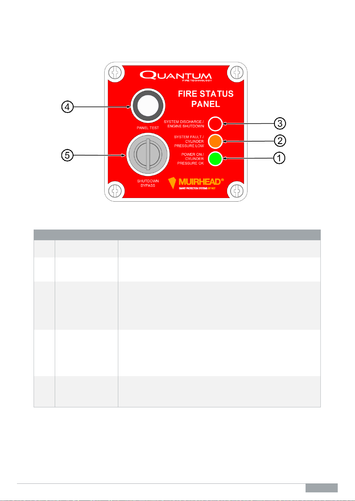
1. Perform a visual inspection; include the following:
a) Control unit
b) Wiring connections and looms
c) Fire suppression tank pressure switch (low)
d) Fire suppression tank pressure switch (discharge)
2. Perform a system test as per the following:
a) Turn the ignition key to the on position and with the cylinder pressure correct, the alert indicator will
illuminate green. The output to the ETR circuit will be activated.
b) Turn the ignition key to the off position and with the cylinder pressure correct, the green alert indicator
and ETR output will turn off. The auxiliary output will turn on.
c) Push and hold the panel test button. The green alert indicator will turn off and the amber alert indicator
will turn on for two seconds. The red alert indicator will switch on after the pre-set period. The ETR
output will turn off and the auxiliary output will turn on. The alarm will be active in this state. When the
panel test button is released, the system will revert to the run state.
d) To check the low cylinder pressure circuit, open circuit the wire at input 1 pressure switch (1200 kPa).
When open, the green alert indicator will switch off, the amber alert indicator will switch on and the
alarm will pulse on and then off. In this state, the alarm will pulse every 30 seconds.
e) To check the cylinder discharged circuit, open circuit the wire at input 2 cylinder discharged pressure
switch. The red alert indicator will switch on and the alarm will be active and pulse for last two seconds
prior to shutdown. Once the shutdown has occurred, the alarm will stay active.
f) Repeat part (e) but push the panel test button during the six-second cycle. This will extend the
shutdown for 20 seconds. During this override period, the alarm will stay active. The delay extension
will only operate once.
g) Once part (f) is performed, insert the key into the key switch and turn to activate it. This will override
the ETR circuit only. The alarm will stay active.
Note
1. Once the system test has been completed, turn the key switch off and ensure all wiring is reconnected to
the original position. Refer to the external wiring diagram in this manual.
2. Once the following has been completed;
a) system has been discharged, or
b) a discharged test has been carried out, AND the ETR output has switched off (shutting down the
machine), then,
the battery power to the unit must be cycled to reset the system.
Turning the ignition on and off WILL NOT RESET the system.
Parts List
Part No.
Description
16936
Fire system status panel
0475
Tank pressure switch low warning 1200 kPa (not supplied with unit)
2348
Tank pressure switch discharge 900 kPa (not supplied with unit)

M1374.docx | Rev 1.0 | Modified on 31/03/2022 | © Remote Control Technologies Pty Ltd
11 | 16
Technical Specifications
Dimensions, control unit only:
Length: 120 mm | Width: 80 mm | Height/Depth: 55 mm
Dimensions, boxed for freight:
Length: 235 mm | Width: 130 mm | Height/Depth: 127 mm
Weight, control unit only:
0.5 kg
Weight, including loom/packaging for
freight:
0.7 kg
Input nominal voltage:
12/24 Vdc
Operating temperate range:
−40 to +80 °C
Connection types:
8-pin Deutsch receptacle
Inputs:
Earth, ignition, battery
Min & max input voltage:
7 to 35 Vdc
Current draw (device only):
12 V –Fire system Idle : 14 mA
–Fire system faulting : 21 mA
24 V –Fire system Idle : 22 mA
–Fire system faulting : 31 mA
Output current rating:
8 A continuous
Enclosure type:
ABS
Environmental protection IP rating:
IP65
Programming/Adjustment:
Yes
Compliance and Standards
1. AS/NZS CISPR 22:2009 Class B. Information technology equipment –Radio disturbance characteristics
–Limits and methods of measurement.
2. AS/NZS CISPR 25:2008, Vehicles, boats, and internal combustion engines –Radio disturbance
characteristics - Limits and methods of measurement for the protection of on-board receivers.
3. ISO 7637-2:2011 Road vehicles –Electrical disturbances from conduction and coupling - Part 2: Electrical
transient conduction along supply lines only (Test Pulses 1, 2a, 2b, 3a and 3b).
4. ISO 16750-2:2012 Road vehicles –Environmental conditions and testing for electrical and electronic
equipment - Part 2: Electrical loads. Section 4.6.3 - Starting Profile (Test Pulse 4).
5. ISO 16750-2:2012 Road vehicles –Environmental conditions and testing for electrical and electronic
equipment - Part 2: Electrical loads. Section 4.6.4.2.3 - Load Dump, Central Suppression (Test Pulse 5b).
6. ISO 7637-2:2011 Road vehicles –Electrical disturbance by conduction and coupling, Part 2: Electrical
transient conduction along supply lines only. Subpart 4.3 Voltage Transient Emissions Test 5.
7. ISO 11452-2:2004 Road vehicles –Component test methods for electrical disturbances from narrowband
radiated electromagnetic energy –Part 2: Absorber - lined shielded enclosure methods (ALSE).
8. ISO 11452-4:2011 Road vehicles –Component test methods for electrical disturbances from narrowband
radiated electromagnetic energy –Part 4: Harness excitation methods (BCI).
9. ISO 10605:2008 Road vehicles –Test methods for electrical disturbances from electrostatic discharge,
Section 8, Component immunity test method (Powered-up test).

12 | 16
M1374.docx | Rev 1.0 | Modified on 31/03/2022 | © Remote Control Technologies Pty Ltd
Troubleshooting
Figure 3 Flowchart FC0107 –Troubleshooting flowchart

M1374.docx | Rev 1.0 | Modified on 31/03/2022 | © Remote Control Technologies Pty Ltd
13 | 16
Glossary
A
Amp (Ampere)
MIN
Minimum
ac
alternating current
mm
millimetres
AMS
Advanced Management System
mW
Milliwatts
Aux
Auxiliary Output
N/A
Not Applicable
CAN
Controller Area Network
N/C
Normally Closed
CMIO
ControlMaster®Input Output PCB
N/O
Normally Open
CMR
ControlMaster®Receiver
OEM
Original Equipment Manufacturer
CMT
ControlMaster®Transmitter
O/P
Outputs
CM2200
ControlMaster®2200 Remote Set
Out
Output
COMMS
Communications
PB
Push Button
CPU
Central Processor Unit
PC
Personal Computer
dc
direct current
PCB
Printed Circuit Board
E.G.
For example
PIN
Personal Identification Number
ETR
Energised To Run
PLC
Programmable Logic Controller
ETS
Energised To Stop
POT
Potentiometer
ESD
Engine Shutdown
PPM
Pulses Per Metre
FET
Field Effect Transistor
PWM
Pulse Width Modulation
GND
Ground
PWR
Power
H
Hours
Rev
Revision
HEX
Hexadecimal Numbering System
RF
Radio Frequency
ID
Identity
RH
Relative Humidity
i.e
that is
rpm
Revolutions per minute
In
Input
Rx
Receiver
IP
Ingress Protection
RS232
Recommended Standard (number 232)
for serial data transfer
kg
Kilogram
SYS
System
km/h
Kilometres Per Hour
ToV
Text On Video
LCD
Liquid Crystal Display
Tx
Transmitter
LED
Light Emitting Diode
USB
Universal Serial Bus
LK
Link
V
Volts
M
Minutes
°C
Degrees Centigrade
mA
Milliamps
#
Number
MAX
Maximum
<
Less Than
MCU
Multi-Control Unit
>
Greater Than
MFU
Multi-Function Unit
%
Percentage
MHz
Mega Hertz (million(s) cycles per
second)

M1374.docx | Rev 1.0 | Modified on 31/03/2022 | © Remote Control Technologies Pty Ltd
15 | 16
Revision History
Rev
Date
By
Details of change
1.0
31/03/2022
JB
Initial document draft and approval

Discover more: www.rct-global.com
sales@rct-global.com
AUSTRALIA: +61 (0) 8 9353 6577
AFRICA: +27 (0) 83 292 4246
CANADA: +1 705 590 4001
RUSSIA / CIS: +7 (910) 411 11-74
SOUTH AMERICA: +56 3 5229 9409
USA: +1 801 938 9214
Table of contents