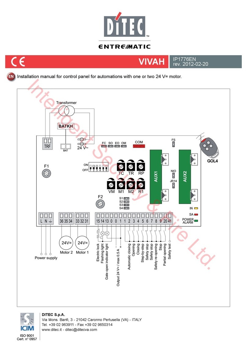
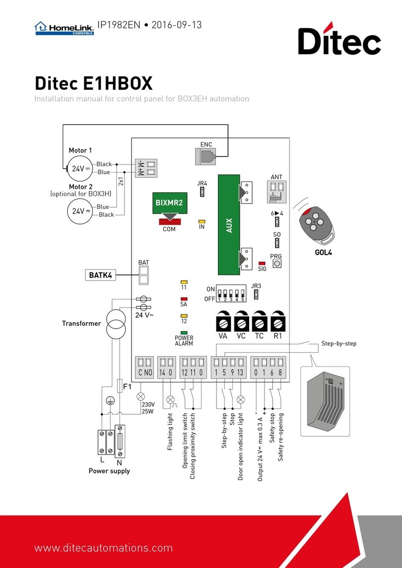
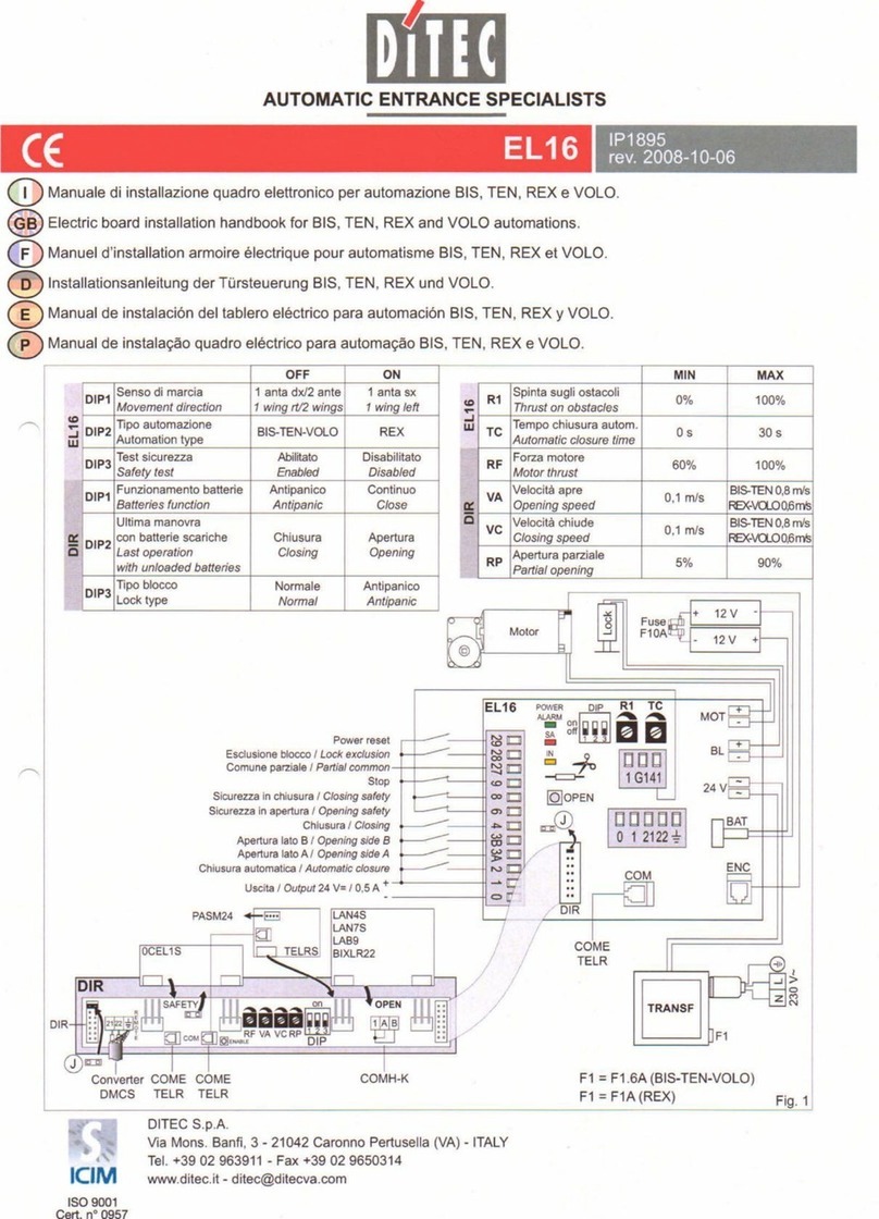
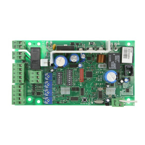
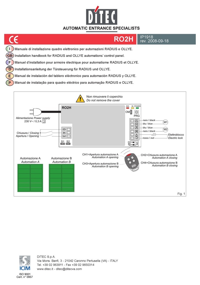
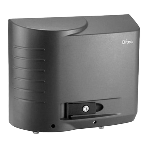
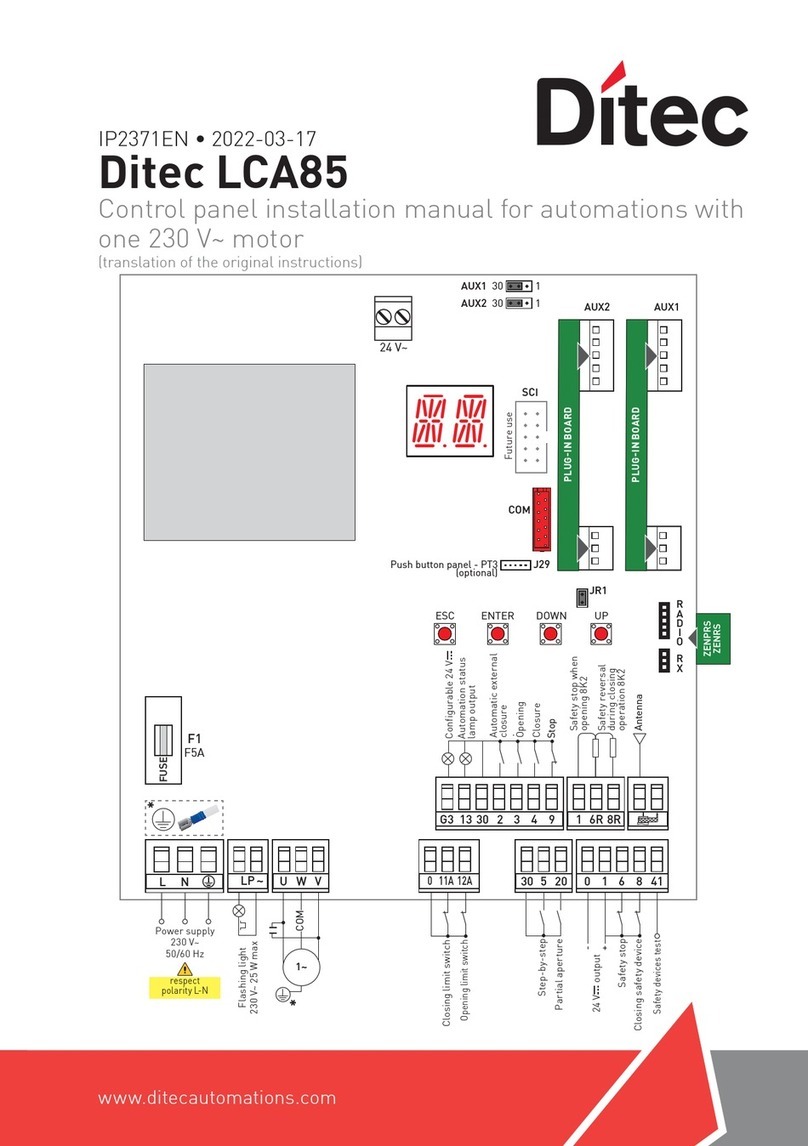
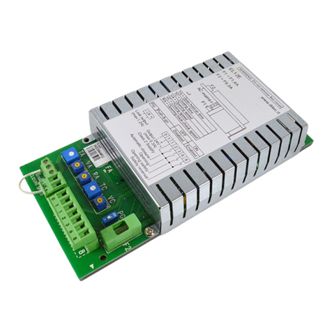
DITEC EL20 System manual

DITEC S.p.A.
Via Mons. Banfi, 3 - 21042 Caronno Pertusella (VA) - ITALY
Tel. +39 02 963911 - Fax +39 02 9650314
EL20 IP1951
rev. 2008-04-15
I
P
E
D
F
GB
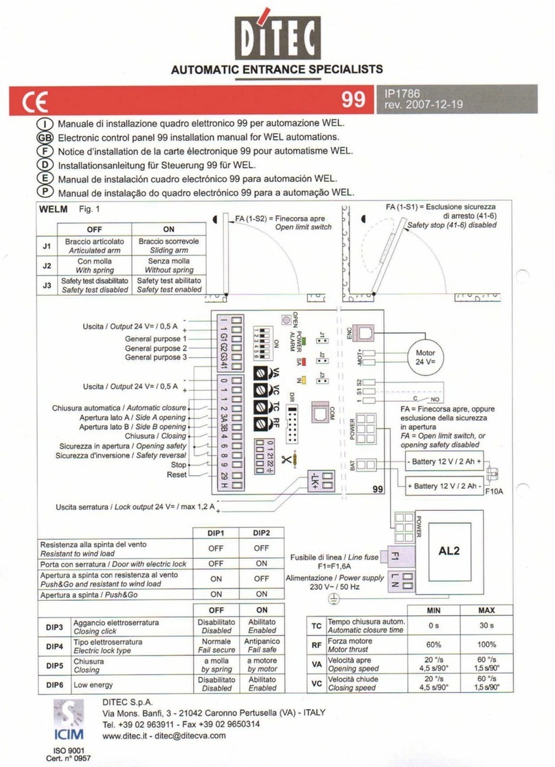
Manuale di installazione quadro elettronico per automazione VALOR.
Electric board installation handbook for VALOR automations.
Manuel d’installation armoire électrique pour automatisme VALOR.
Installationsanleitung der Automatiktürsteuerung VALOR.
Manual de instalación del tablero eléctrico para automación VALOR.
Manual de instalação quadro eléctrico para automação VALOR.
MOT
COM
VA
DIP
OPEN
J1J2J3
VC TC RP R1
on
off
POWER
ALARM
SA
IN
+
-
LK +
-
AUX
BAT
POWER
+
-
ENC
Motor
230 V~
F1=F1,6A
AL2
Lock
1 2 3 4 5 6
0 1 1 2 3A3B 9 27 28 29
0 1 6 8 41
R1SR R2
1 S1 S2
L N
P1 SP P2
0 1 21 22
EL20
Uscita / Output 24 V= / 0,5 A
Sicurezza in chiusura / Closing safety
Sicurezza in apertura / Opening safety
A
pertura parz. lato B / Part. opening side B
Apertura parz. lato A / Part. opening side A
Power reset
Esclusione blocco / Lock exclusion
Stop
Apertura lato B / Opening side B
Apertura lato A / Opening side A
Chiusura automatica / Automatic closure
+
-
COME
TELR
MD1
CELPR
-
-
+
+
Fuse
F10A
12 V
12 V
OFF ON
DIP1 Tipo elettroblocco
Electric lock type
Normale
Fail secure
Antipanico
Fail safe
DIP2 Senso di marcia
Movement direction
1 anta dx/2 ante
1wingrt/2wings
1 anta sx
1 wing left
DIP3 Funzionamento batterie
Batteries function
Antipanico
Antipanic
Continuo
Continuos
DIP4
Ultima manovra
con batterie scariche
Last operation
with unloaded batteries
Chiusura
Closing
Apertura
Opening
DIP5 Peso ante
Wings weight < 200 Kg > 200 Kg
DIP6 USO FUTURO
FUTURE USE / /
MIN MAX
VA Velocità apre
Opening speed 0,1 m/s 0,8 m/s
VC Velocità chiude
Closing speed 0,1 m/s 0,8 m/s
TC Tempo chiusura autom.
Automatic closure time 0 s 30 s
RP Apertura parziale
Partial opening 5% 90%
R1 Spinta sugli ostacoli
Thrust on obstacles 0% 100%

10
EL20 - IP1951
GB
GENERAL SAFETY WARNINGS
This installation manual is intended for professionally competent personnel only. Installation, electrical connections and
adjustments must be performed in accordance with Good Working Methods and in compliance with the present standards.
Read the instructions carefully before installing the product. Bad installation could be dangerous. Before installing the product,
make sure it is in perfect condition. Use original spare parts only for repairs or replacements of products.
1. TECHNICAL DATA
Refer to the technical specifications and EC Declaration of Conformity in the VALOR automation’s manuals.
2. ELECTRICAL CONNECTIONS
Warning: make a jumper on all N.C. contacts if not in use. The terminals with the same number are equal.
2.1 Commands
Command Function Description
1 2 N.O. AUTOMATIC CLOSING A permanent contact enables the automatic closing. Selector switches
COMH-K and COME automatically select the automatic closing.
1 3A
1 3B
N.O. SIDE A OPENING
SIDE B OPENING
The opening manoeuvre starts when the contact is closed.
27 3A
27 3B
N.O.
N.O.
SIDE A PARTIAL OPENING
SIDE B PARTIAL OPENING
Partial opening occurs when the contact is closed.
1 9 N.C. STOP All movements are stopped when the contact is opened. All normal
or emergency operations are excluded when the contact is opened.
Warning: when the contact closes again the door proceeds with the
interrupted manoeuvre.
1 28 N.O. BLOCK EXCLUSION The block operation is excluded when the contact is closed.
The exclusion is automatic in the fully open and partial two-way posi-
tions with COMH, COMK and COME.
1 29 N.O. POWER RESET All acquired data is annulled when the contact is closed.
The automation can start acquisition again after 3 seconds.
2.2 Non testable safety devices
Command Function Description
41 6 N.C. OPENING SAFETY With J3=ON the opening speed is reduced in the last 500 mm of the
door wing stroke when the contacts are opened.
41 8 N.C. REVERSAL SAFETY
CONTACT
With J3=ON the opening of the contact during the closure manoeuvre
causes the movement to invert (opening).
2.3 Testable safety devices
Command Function Description
1 6 N.C. OPENING SAFETY The opening speed is reduced in the last 500 mm of the door wing
stroke when the contacts are opened.
1 8 N.C. REVERSAL SAFETY
CONTACT
The opening of the contact during the closure manoeuvre causes the
movement to invert (opening).
41 + SAFETY TEST With J3=ON connect terminal 41 of the control panel to the correspon-
ding test terminal on the safety device. Terminal 41 activates a test of
the safety device on each cycle. If the test fails the SA led ashes and
the test is repeated.

GB
11 EL20 - IP1951
Output Value Description
0 -
1 + 24 V= / 0,5 A (max) Accessories power supply. External accessories power supply output.
Note: the maximum absorption of 0.5A corresponds to the sum of all terminals 1.
COM Allows the connection of possible commands for distances under 4,5 m.
0 -
1 +
21
22
Allows the connection of 1 or 2 COME selector switches or the display
or the connection of the DMCS software,
or the network connection of a maximum of 4 automations.
Note: use a data transmission type screened cable.
FUTURE USE
OPEN OPENING The opening operation is activated with a brief press.
SETTINGS RESET Keep the OPEN button pressed (for 4 s), until the IN LED starts to ash. To
conrm the operation, press the OPEN button again for 2 seconds within 4
seconds.
The SETTINGS RESET annuls all the remote software settings made via
DMCS, MD1, TEL2, COME. After SETTINGS RESET it is possible to adjust
the control panel directly.
- MOT +
ENCODER
Motor-encoder connection. Connect the motor and encoder to the control
panel by means of the supplied cables.
POWER AL2 power supply unit connection.
VALABE 2 x 12 V / 1,2 Ah Anti-panic battery kit (VALABE). With DIP3=OFF with the mains power sup-
ply off, the automation will carry out an opening operation at low speed. When
the door is open the power supply is disconnected from the control panel.
To charge the batteries, connect the mains power and the battery kit at least 30
minutes before starting the system.
Warning: to allow charging, the battery kit must be connected to the control
panel at all times. Periodically check the efciency of the battery kit.
VALABC 2 x 12 V / 7 Ah Continuous mode battery kit (VALABC). Con DIP3=ON with the mains po-
wer supply off, the battery kit will guarantee continuous operation.
With DIP4 select the last operation with the batteries at.
To charge the batteries, connect the mains power and the battery kit at least 30
minutes before starting the system.
Warning: to allow charging, the battery kit must be connected to the control
panel at all times. Periodically check the efciency of the battery kit.
- AUX + 24 V= / 200 mA Bistable blocking device. Bistable blocking device power supply output
(auxiliary coil).
- LK + 24 V= / 1 A Electric block. Blocking device power supply output.
2.4 Outputs and accessories
2.5 Limit switch connection
Command Function Description
1 S1 N.O. FUTURE USE
1 S2 N.O. FUTURE USE
12
EL20 - IP1951
GB
2.6 CELPR photocell connection
P1 R1
J1=ON
P1 SP P2 R1SR R2
2.7 Trimmer
Description MIN. MAX.
VA Opening speed. Adjust the opening speed. 0,1 m/s 0,8 m/s
VC Closing speed. Adjust the closing speed. 0,1 m/s 0,8 m/s
TC Automatic closure time. Adjust the time that passes between the end of the opening manoeuvre
and the start of the automatic closing manoeuvre. 0 s 30 s
RP Partial opening. Adjust the range when the command is given between 27-3A (3B). With the trimmer
at minimum, the opening is equal to 5% of the normal opening; with the trimmer at maximum, the
opening is equal to 90% of the normal opening.
5% 90%
R1 Thrust on obstacles. If there is an obstacle, stop the movement during the opening operation, or
invert it during the closing operation. After the obstacle has been removed, the door automatically
searches for the stop, continuing its stroke at the learning speed.
0% 100%
2.8 Dip-Switches
Description OFF ON
DIP1 Block type. Normal block/bistable block. Anti-panic block.
DIP2 Direction selection.
The opening direction is intended by viewing the
automation from the side being examined.
Right-hand opening for single
door wing automations.
Selection for double door wing
automations.
Left-hand opening for single door
wing automations.
DIP3 Batteries. Anti-panic operation. Continuos operation.
DIP4 Flat batteries. Last operation closing. Last operation opening.
DIP5 Door weight. < 200 Kg > 200 Kg
DIP6 FUTURE USE / /
P1
R2
R1
J1=ON
P2
P1 SP P2 R1SR R2

GB
13 EL20 - IP1951
LED ON Flashing
POWER ALARM 24 V= power supply. Encoder / automation fault.
IN During the commands: 1-3A, 1-3B, 27-3A, 27-3B. Flashes once each time the dip switch and command
1-2 status changes.
SA Safeties 41-6 and 41-8 open. Safety test failure.
2.10 Signals
2.9 Jumper
Description OFF ON
J1 Integrated photocell. Disabled. Enabled.
J2 FUTURE USE / /
J3 Safety test terminal 41. Disabled. Enabled.
3. STARTING
ATTENTION: Before performing any type of operation, make sure that the automation is turned off and the batteries are
disconnected.
The operations related to point 3.4 are performed without safeties.
The trimmer can only be adjusted with the automation idle.
3.1 Select the correct direction with DIP2.
3.2 Set trimmer TC to the minimum and trimmers VA, VC, RP, R1 halfway.
3.3 Make a jumper on the safeties (41-6 and 41-8) and the stop (1-9). Set J1=OFF.
3.4 Turn on (mains and batteries). SETTINGS RESET with the OPEN button as indicated in paragraph 2.4.
Attention: the control panel performs an automatic POWER RESET on each start and the first opening or closing manoeuvre
is performed at low speed allowing the automatic self-learning of the stop positions (acquisition).
Check that the automation is operating correctly with further opening and closing commands and set the desired speed with
VA and VC.
3.5 Adjust the thrust on obstacles with trimmer R1.
3.6 Remove the jumper and connect the safeties (41-6 and 41-8) and the stop (1-9). If the CELPR photocells are present, set
J1=ON.
3.7 Select the battery function with DIP3 and DIP4.
3.8 Adjust the automatic closing with the TC (enabled by command 1-2).
3.9 Set the partial opening with RP if required.
3.10 Connect possible accessories and check they are functioning.
3.11 If the automation encounters an obstacle during closure, it is detected and the automation opens again.
If the automation encounters an obstacle during opening, it is detected and the automation stops.
If the obstacle is detected twice in a row, it is considered as the new stop until it is removed.
Warning: check the operating force and that the contact force between the door and the obstacle is lower than that indicated
by the DIN 18650-1 standard.

14
EL20 - IP1951
GB
Problem Possible causes Remedy
The automation does not open
and close or does not perform
the set operations.
Operations selector switch fault. SETTINGS RESET with the OPEN button as indi-
cated in paragraph 2.4.
Warning: this operation may cancel previously
carried out remote adjustments.
Operations selector switch incorrectly set. Check and correct the settings of the operations
selector switch.
The automation does not open
and close.
No power.
(POWER ALARM led off).
Check that the control panel is on.
Short circuited accessories. Disconnect all accessories from terminals 0-1 (a
voltage of 24V= must be present) and reconnect
them one at a time.
Blown line fuse. Replace the transformer fuse.
The stop contact is open. Check terminal 9 of the control panel and the po-
sition of the operations selector (if present).
The automation is locked by bolts and locks. Check that the door moves freely.
The automation opens but does
not close.
The safety contacts are open.
(SA LED on).
Check terminals 6 and 8 of the control panel.
The photocells are activated.
(SA LED on).
Check that the photocells are clean and operating
correctly.
Incorrect J1 setting.
(SA LED on).
If J1=ON, check the effective connection of the
CELPR photocells.
The radars are activated. Check that the radar is not subjected to vibrations,
does not make false readings or the presence of
moving objects within its range.
The automatic closing does not work. Check jumper 1-2 and the position of the opera-
tions selector (if present).
Incorrect J3 setting.
(ashing SA LED)
Check the connections of the safeties as illustra-
ted in paragraphs 2.1 and 2.2.
The external safeties do not ac-
tivate.
Incorrect connections between the photocells
and the control panel.
Connect the N.C. safety contacts together in seri-
es and remove possible jumpers.
The automation opens on its
own.
The radars are instable or detect moving
objects.
Check that the radar is not subjected to vibrations,
does not make false readings or the presence of
moving objects within its range.
The automation opens/closes
briey and then stops.
Defective encoder.
(ashing POWER ALARM LED).
Replace the encoder.
Inverted motor wires.
(ashing POWER ALARM LED).
Check the motor wires.
There is a presence of friction. Manually check that the door wings move freely
and adjust the door wing in height by lifting it.
4. TROUBLESHOOTING

GB
15 EL20 - IP1951
5. APPLICATION EXAMPLE WITHOUT SELECTOR
The automation opens with commands 1-3A, 1-3B of the RADAR, and automatically closes with jumper 1-2.
Make the safety on the passage opening with CELPR photocells.
The switch between 1-9 stops the automation at that point and no other normal or emergency operation is permitted.
Contact 1-29 can be used for the POWER RESET of the control panel.
6. APPLICATION EXAMPLE WITH COMH-COMK SELECTOR
The automation opens with the 1-3A, 1-3B RADAR commands and automatically closes based on the operation chosen on the
selector. Make the safety across the passage opening with the CELPR photocells.
With the selector in the STOP position all normal and emergency operations are excluded.
Contacts 41-6 and 41-8 are independent from the selector, therefore they must have jumpers if not in use.
The POWER RESET of the control panel is available on the operations selector switch.
POWER
RESET
STOP
RADAR BRADAR A
24 V
+ -
24 V
+ -
COM
VA
DIP
OPEN
J1J2J3
VC TC RP R1
on
off
POWER
ALARM
SA
IN
1 2 3 4 5 6
0 1 1 2 3A3B 9 27 28 29
0 1 6 8 41
0 1 21 22
EL20
P1 R1
P1 SP P2
R1SR R2
CELPR
RADAR BRADAR A
24 V
+ -
24 V
+ -
COM
VA
DIP
VC TC RP R1
on
off
POWER
ALARM
SA
IN
1 2 3 4 5 6
0 1 1 2 3A3B 9 27 28 29
0 1 6 8 41
0 1 21 22
EL20
272829 12AB9
COMH
COMK
OPEN
J1J2J3
P1 R1
P1 SP P2
R1SR R2
CELPR

16
EL20 - IP1951
GB
7. APPLICATION EXAMPLE WITH COME SELECTOR
The automation opens with the 1-3A, 1-3B RADAR commands and automatically closes based on the operation chosen on the
selector. Makes the safety across the passage opening with the CELPR photocells.
With the selector in the STOP position all normal and emergency operations are excluded.
Contacts 41-6 and 41-8 are independent from the selector, therefore they must have jumpers if not in use.
Contact 1-9 is in series to the STOP, selector set, therefore it must have a jumper if not used.
The POWER RESET of the control panel is available on the operations selector switch through a key combination.
A MD1-MDA device can be connected to access the adjustment and the diagnosis of the control panel.
8. APPLICATION EXAMPLE WITH AUTOCONTROLLED SAFETY DEVICE
Autocontrolled safety devices can be connected as illustrated in the diagram.
Set J1=OFF.
Device 1 performs the safety on the left side during opening.
Device 2 performs the reverse safety contact on the passage opening during the closing operation.
Device 3 performs the safety on the right side during opening.
2 3
1
COM
VA
DIP
OPEN
J1J2J3
VC TC RP R1
on
off
POWER
ALARM
SA
IN
1 2 3 4 5 6
0 1 1 2 3A3B 9 27 28 29
0 1 6 8 41
0 1 21 22
EL20
COME CELPR
1
4 5 6
3
2
MD1-MDA
RADAR BRADAR A
24 V
+ -
24 V
+ -
P1 R1
P1 SP P2
R1SR R2
COM
VA
DIP
OPEN
J2J3
VC TC RP R1
on
off
POWER
ALARM
SA
IN
1 2 3 4 5 6
0 1 1 2 3A3B 9 27 28 29
0 1 6 8 41
R1SR R2
P1 SP P2
0 1 21 22
EL20
41
24 V
+ -
41
24 V
+ -
1
41
24 V
+ -
2 3
J1

GB
17 EL20 - IP1951
9. AUTOMATIONS IN PARALLEL
It is possible to command two automations [DRIVE1] and [DRIVE2] side by side, making the connections
indicated in the diagram with the electronic selector switch COME.
Set J1=OFF and J3=OFF on both control panels.
Note: adjust the automatic closing trimmers (TC) and the opening (VA) and closing (VC) speed trimmers in the
same position on both automations so as to obtain the simultaneous opening and closing of the door wings.
COM
VA
DIP
OPEN
VC TC RP R1
COM
on
off
POWER
ALARM
SA
IN
1 2 3 4 5 6
0 1 1 2 3A 3B 9 27 28 29
0 1 6 8 41
EL20
COME
SICUR2
1
4 5 6
3
2
RADAR BRADAR A
24 V
+ -
24 V
+ -
TX RX
P1 SP P2
R1SR R2
VA
DIP
OPEN
J1J2J3
VC TC RP R1
on
off
POWER
ALARM
SA
IN
1 2 3 4 5 6
0 1 1 2 3A 3B 9 27 28 29
0 1 6 8 41
EL20
DRIVE1 DRIVE2
J1J2J3
P1 SP P2
R1SR R2
0 1 21 22 0 1 21 22
All right reserved
All data and specications have been drawn up and checked with the greatest care. The manufacturer cannot however take any
responsibility for eventual errors, ommisions or incomplete data due to technical or illustrative purposes.
Table of contents
Other DITEC Control Panel manuals

DITEC
DITEC E1HBOX User manual

DITEC
DITEC EL16 System manual

DITEC
DITEC Entrematic HomeLink E2H User manual

DITEC
DITEC RO2H System manual

DITEC
DITEC E2J User manual

DITEC
DITEC LCU30H User manual

DITEC
DITEC LCA70 User manual

DITEC
DITEC LCU43A User manual

DITEC
DITEC EL12E User manual

DITEC
DITEC LCA85 User manual
Popular Control Panel manuals by other brands

IBM
IBM Power System 5105-22E manual

Geberit
Geberit AquaClean Sela 147.041.SI.1 user manual

Rokonet
Rokonet ORBiT-14 installation manual

DSC ELECTRONICS
DSC ELECTRONICS DF-C 63 Series user manual

elsner elektronik
elsner elektronik WS1 Style Series Brief Instruction

LOMBARDINI MARINE
LOMBARDINI MARINE KOHLER OMNILINK owner's manual