Muller Elektronik SPRAYDOS User manual

Installation and operating instructions
SPRAYDOS
Version: V2.20160707
30221021-02-EN
Read and follow these operating instructions.
Keep these operating instructions in a safe place for later
reference.

Company details
Document: Installation and operating instructions
Product: SPRAYDOS
Document number: 30221021-02-EN
As of software version: 15.10.13
Original language: German
Müller-Elektronik GmbH & Co.KG
Franz-Kleine-Straße 18
33154 Salzkotten
Germany
Phone: ++49 (0) 5258 / 9834 - 0
Fax: ++49 (0) 5258 / 9834 - 90
Email: info@mueller-elektronik.de
Homepage: http://www.mueller-elektronik.de

Copyright Müller-Elektronik GmbH & Co.KG, Installation and operating instructions SPRAYDOS (07.2016) Page - 3 -
Table of contents
1INTRODUCTION......................................................................................................................................... 5
2SAFETY INSTRUCTIONS .......................................................................................................................... 6
2.1 Intended use .............................................................................................................................................. 6
2.2 Basic safety instructions.......................................................................................................................... 6
2.3 Layout and meaning of warnings ............................................................................................................ 6
2.4 Safety notice for the subsequent installation of electrical
and electronic devices and /or components........................................................................................... 7
3EC DECLARATION OF CONFORMITY ..................................................................................................... 8
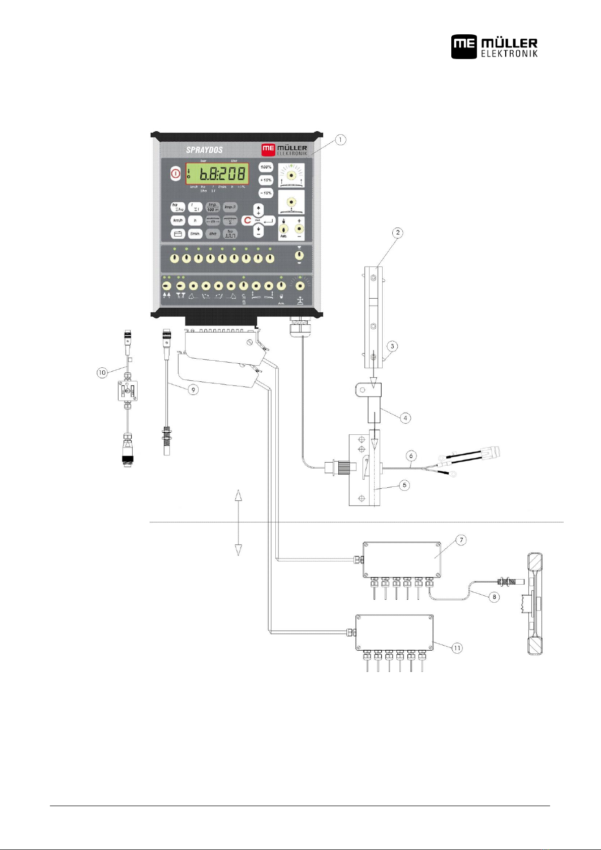
4OVERVIEW AND SYSTEM DESCRIPTION ............................................................................................... 9
4.1 Overview..................................................................................................................................................... 9
4.2 System description ................................................................................................................................. 11
5INSTALLATION INSTRUCTIONS ............................................................................................................ 12
5.1 Console and computer............................................................................................................................ 12
5.2 Battery connecting cable [6] .................................................................................................................. 12
5.3 Sensor X (calculation of the distance) .................................................................................................. 14
5.4 Adapter cable for tractors with signal socket....................................................................................... 14
5.5 Connection on the field sprayer............................................................................................................. 15
6OPERATING INSTRUCTIONS ................................................................................................................. 16
6.1 Function description............................................................................................................................... 16
6.2 Description of the input of machine data.............................................................................................. 16
6.2.1 "Working width" key ...................................................................................................................... 16
6.2.2 "Impulses/100m" key .................................................................................................................... 17
6.2.3 "Number of boom sections" key ................................................................................................... 17
6.2.4 "Pre-set rate - l/ha" key ................................................................................................................. 17
6.2.5 "Impulses / litre" key ..................................................................................................................... 18
6.2.5.1 Impulses per litre input .............................................................................................................................. 18
6.2.5.2 Tank method.............................................................................................................................................. 18
6.2.5.3 Nozzle method........................................................................................................................................... 18
6.2.6 "Type" key .................................................................................................................................... 19
6.2.6.1 Manifold type ............................................................................................................................................. 19
6.2.6.2 Control constants....................................................................................................................................... 20
6.2.7 "+ 10 %" , "- 10 %" ,"100 %" keys ..................................................................... 21

Page - 4 - Copyright Müller-Elektronik GmbH & Co. KG, Installation and operating instructions SPRAYDOS (07.2016)
6.3 Description of the operating data keys ................................................................................................. 21
6.3.1 "Start function"........................................................................................................................................... 21
6.3.2 "Area / total area" ......................................................................................................................... 21
6.3.3 "Time" key .................................................................................................................................... 21
6.3.4 "Spraying fluid l/min" key .............................................................................................................. 21
6.3.5 "Spraying fluid l and l" key ......................................................................................................... 21
6.3.6 "Speed" key .................................................................................................................................. 22
6.3.7 "Tank content" key ........................................................................................................................ 22
6.4 Spraying function switch........................................................................................................................ 22
6.4.1 Boom section main switch ................................................................................................................ 22
6.4.2 Manual/automatic switch ................................................................................................................... 22
6.4.3 Spraying pressure +/- key ................................................................................................................. 22
6.4.4 Boom section switch ............................................................................................................ 23
6.4.5 Configuring the section switches............................................................................................................... 23
6.5 Hydraulic functions switch..................................................................................................................... 23
6.5.1 Short SPRAYDOS version ........................................................................................................................ 23
6.5.2 Long SPRAYDOS version......................................................................................................................... 23
6.6 Operating procedure ............................................................................................................................... 23
6.7 Calibrating hydraulic functions.............................................................................................................. 24
6.7.1 Activating calibration mode........................................................................................................................ 25
6.7.2 Calibrating the boom control...................................................................................................................... 25
6.7.3 Calibrating the drawbar steering................................................................................................................ 26
7MAINTENANCE........................................................................................................................................ 28
7.1 Computer.................................................................................................................................................. 28
7.2 Flow meter................................................................................................................................................ 28
8APPENDIX ................................................................................................................................................ 29
8.1 Technical data.......................................................................................................................................... 29
8.1.1 Long SPRAYDOS version......................................................................................................................... 29
8.1.2 Short SPRAYDOS version ........................................................................................................................ 29
9LIST OF DIAGRAMS ................................................................................................................................ 30

Copyright Müller-Elektronik GmbH & Co.KG, Installation and operating instructions SPRAYDOS (07.2016) Page - 5 -
1Introduction
The SPRAYDOS board computer is a new development on the basis of the well tried and tested SPRAY-Control board
computer. The SPRAYDOS has up to 9 boom section switches with a main switch, the manual or automatic regulation of
the spray rate and up to 4 hydraulic functions (the long version allows a further 10 hydraulic functions as soon as foam
marker and corner nozzles). The current speed and the current spray rate are displayed simultaneously.
If an automatic pressure sensor is installed, the pressure is displayed instead of the speed. The speed appears on the
display when the km/h key is pressed for about 5 seconds. Specific applications can be carried out by pressing the +/- 10%
key. The pre-set rate resets by means of the l/ha key. The spray rate is adhered to accurately even when the speed varies.

Page - 6 - Copyright Müller-Elektronik GmbH & Co. KG, Installation and operating instructions SPRAYDOS (07.2016)
2Safety instructions
2.1 Intended use
The SPRAYDOS is specified exclusively for agricultural use and in wine, fruit and hop growing. The manufacturer
takes no responsibility for any installation or application outwith this area.
The manufacturer does not accept liability for damage to persons or property resulting from unspecified use. In
such cases all risks are the responsibility of the user.
Specified implementation also includes adhering to the operation and maintenance requirements stipulated by the
manufacturer.
Relevant accident prevention regulations as well as other generally recognised safety, industrial, health and road
traffic rules are to be adhered to. In addition the manufacturer accepts no liability in cases where arbitrary
modifications have been made to the device.
2.2 Basic safety instructions
Observe the following recommended precautions and safety instructions:
Do not remove any safety devices or labels.
Before using the SPRAYDOS read and understand this guide. It is of equal importance that others operating this
device also read und understand the manual.
During maintenance or when using a battery charger, switch off the power supply.
Never service or repair the device while the job computer is switched on.
Before welding on the tractor or on an attached machine, interrupt the power supply to the SPRAYDOS.
Only use a soft damp cloth with clear water or a little glass cleaning agent to clean the SPRAYDOS.
Operate the keys with your finger tips but avoid using fingernails.
Should any part of this guide remain incomprehensible after reading, contact the dealer or Mueller-Elektronik
Service for further clarification before using the SPRAYDOS.
Read carefully all safety instructions in the manual.
Learn how to operate the SPRAYDOS correctly. Nobody is to operate the machine without exact instructions.
Keep the SPRAYDOS and the spare parts in good condition. Unspecified alterations can impair the function and/or
safety and affect the life span of the machine.
2.3 Layout and meaning of warnings
All safety instructions found in these Operating Instructions are composed in accordance with the following pattern:
WARNING
This signal word identifies medium-risk hazards, which could potentially cause death or serious
physical injury, if not avoided.
CAUTION
This signal word identifies low-risk hazards, which could potentially cause minor or moderate
physical injury or damage to property, if not avoided.

Copyright Müller-Elektronik GmbH & Co.KG, Installation and operating instructions SPRAYDOS (07.2016) Page - 7 -
NOTICE
This signal word identifies actions which could lead to operational malfunctions if performed
incorrectly.
These actions require that you operate in a precise and cautious manner in order to produce
optimum work results.
2.4 Safety notice for the subsequent installation of electrical and electronic devices
and /or components
Present-day agricultural machines are equipped with electronic components and devices, whose function can be affected
by electromagnetic emission from other devices. These influences can lead to endangerment for individuals when the
following safety measures are not adhered to.
When subsequently installing electrical and electronic devices and/or components in a machine with a connection to the
electrical system, the user must take sole responsibility for testing the installation for interference of the vehicle electronics
or other components. This applies in particular to the electronic controls of:
EHR
Front lifting gear
Power take-off shafts
Motor
Gears
Above all it must be ensured that all subsequently installed electrical and electronic components comply with the current
version of the EMC directive 89/336/EWG and carry the CE symbol.
In addition the following requirements must be fulfilled when upgrading with mobile communication systems (e.g. radio,
telephone):
Only approved devices complying to national regulations (e.g. BZT approval in Germany) are to be installed;
The device must be securely installed;
The use of portable or mobile devices inside the vehicle is permissible only via a connection to a permanently
installed outside antenna;
The transmitting unit is to be installed in a position away from the vehicle electronics;
An antenna should only be installed professionally ensuring that there is a good earth connection between the
antenna and the vehicle chassis.
Please refer to the manufacturer's installation instructions for cabling and installation as well as the maximum current
consumption.

Page - 8 - Copyright Müller-Elektronik GmbH & Co. KG, Installation and operating instructions SPRAYDOS (07.2016)
3EC declaration of conformity
This product has been manufactured in conformity with the following national and harmonised standards as specified in the
current EMV Directive 2004/1008/EG:
Dieses Produkt ist in Übereinstimmung mit folgenden nationalen und harmonisierten Normen im Sinne der EMV-Richtlinie
2004/108/EG hergestellt:
EN ISO 14982

Copyright Müller-Elektronik GmbH & Co.KG, Installation and operating instructions SPRAYDOS (07.2016) Page - 9 -
4Overview and system description
4.1 Overview
Diagram 4-1 SPRAYDOS overview
Machine plug
manifold
Machine plug
hydraulic
Basic console
Continuos current socket
DIN 9680
brown
blue
Bracket
Sensor X (Wheel)
Machine signal
distributor for sprayer
Hydraulic signal
distributor –long
SPRAYDOS version
Tractor
Implement
Signal socket
Sensor X

Page - 10 - Copyright Müller-Elektronik GmbH & Co. KG, Installation and operating instructions SPRAYDOS (07.2016)
Übersicht
[1] SPRAYDOS computer
[2] Cap profile rail for mounting the SPRAYDOS
[3] Wing screw to secure the computer
[4] Bracket S for mounting the cap profile rail
[5] Basic console, to be mounted on the tractor cabin. For fitting the bracket with cap profile rail and battery connection.
[6] Battery connecting cable for the SPRAYDOS voltage supply, connection to a 12-volt battery.
[7] Machine signal distributor
Combines the sensor and actuator connections on the machine.
[8] Sensor X (wheel) records distance impulses on the trailed field sprayer.
[9] Sensor X (cardan shaft / wheel)
records speed, impulses on the cardan shaft or front tractor wheel.
[10] Plug for tractor signal socket
records the signals from the installed sensors on the tractor.
[11] Hydraulic signal distributor
Combines the hydraulic connections on the machine (for SPRAYDOS –long version).

Copyright Müller-Elektronik GmbH & Co.KG, Installation and operating instructions SPRAYDOS (07.2016) Page - 11 -
4.2 System description
The SPRAYDOS can be installed on the field sprayer as a fully automatic control instrument. The device carries out an
area-related control of the spray rate regardless of the current speed, the working width and the pre-set rate.
The calculation of the current spray rate, speed, working area, total area, quantity spray as well as the total quantity and the
working time is carried out continuously.
The device consists of the computer [1] and the console [2-5].
A wheel/cardan speed sensor [9] can be connected directly to SPRAYDOS in order to determine the speed.
The SPRAYDOS can be connected directly to the signal socket [10] on the tractor using a connecting cable. By means of a
switch integrated in the connecting cable it is possible to switch between wheel/cardan and a radar device.
CAUTION
If the SPRAYDOS is being used on a trailed field sprayer, no speed sensor is to be connected to
the SPRAYDOS. In this case the speed is measured at the wheel of the field sprayer.
The field sprayer is connected by means of the machine plug (circulation, hydraulic) on the SPRAYDOS.
CAUTION
During transport the SPRAYDOS must be switched off.
If available, the drawbar or axle steering must be set to centre position during transport.

Page - 12 - Copyright Müller-Elektronik GmbH & Co. KG, Installation and operating instructions SPRAYDOS (07.2016)
5Installation instructions
5.1 Console and computer
The basic console [5] must be mounted vibration-free and electroconductive to the cabin on the driver's right-hand side
and within his visual range and reach. The distance to the radio or to the radio antenna should be at least 1 m.
Attach the bracket [4] to the tube of the basic console.
Mount the cap profile rail [2] on to the bracket. Push the SPRAYDOS computer [1] from above on to the profile and
secure using the wing nuts [3].
The console can be swivelled to allow the display to be adjusted to the optimal angle of vision which lies between 45° and
90° from below.
VORSICHT
Please ensure that the computer casing [1] has a lead connection to the tractor's chassis above the
console [2-5]. When mounting, remove the paint from the mounting points.
5.2 Battery connecting cable [6]
Brown cable core
Blue cable core
Free end of the butt connector
Loose ring tongue –ground/0V
Ring tongue +12V
WARNING
Risk of injury caused by short circuit
Connecting the positive terminal and the vehicle mass when working on the battery terminals can
cause a short circuit. This can cause burn injuries to persons.
◦When working on the battery terminals, ensure that no connection is created between the
vehicle battery and the vehicle mass.
◦Remove metallic items such as watches and rings before starting work.
◦When disconnecting the terminals, always begin with the negative terminal.
◦Always begin reconnecting the terminals with the positive terminal.

Copyright Müller-Elektronik GmbH & Co.KG, Installation and operating instructions SPRAYDOS (07.2016) Page - 13 -
WARNING
Danger of injury from explosion of the vehicle battery
If the battery terminals are loose fitting, starting the vehicle can cause the vehicle battery to
overheat. The vehicle battery may then explode.
◦Always tighten the battery terminals firmly after assembly.
CAUTION
Damage to the vehicle’s electrical system
Switching the polarity of the cables can cause damage to the vehicle’s electrical system.
◦Pay attention to the polarity of the cable cores and the terminals.
> Ensure that the vehicle is switched off.
> Insert the blue cable core into the 0V ring tongue .
> Insert the brown cable core into the free end of the butt connector .
> Pinch with a crimping tool.
>
Shrink both of the butt connectors with a heat source (e.g. hot air gun) until the adhesive emerges.
> Connect the ring tongues to the battery terminals of the vehicle battery. Pay attention to the polarity, beginning with
the positive terminal.
> Fasten the battery cable with cable ties. Ensure that there is sufficient distance from moving parts and parts
generating large amounts of heat.
Operating voltage is 12 V and must be taken directly from the battery or from the 12-volt starter. Care should be taken
when laying the cable [6] and it should be shortened if necessary. The crimpon ring terminal for the ground line (blue) and
the end sleeve for strands for the + line (brown) should be fitted using suitable pliers. The end sleeve for strands for the +
line are in the connection clamp of the fuse holder.
brown = + 12 volts
blue = ground
CAUTION
The negative pole on the battery must be connected to the tractor's chassis.

Page - 14 - Copyright Müller-Elektronik GmbH & Co. KG, Installation and operating instructions SPRAYDOS (07.2016)
5.3 Sensor X (calculation of the distance)
Mounting on four-wheel drive tractors:
Mount the hose clamp with a magnet to the cardan shaft.
The sensor must point in the direction of the magnets at a distance
between 5 –10 mm. It is to be mounted vibration-free.
Mounting on tractors without without four-wheel drive:
Install the magnets in the wheel shell using V4A screws
provided, distributing them evenly over the circumference.
The number of magnets depends on the size of the wheel.
The distance travelled from impulse to impulse must not
exceed 60 cm.
Calculation:
Wheel circumference ÷ 60 cm = number of magnets
e.g.: 256 cm ÷ 60 cm = 4.27 = min. 5 magnets
Mount the sensor to the steering knuckle using the bracket
provided so that the end of the sensors is pointing towards the
magnets. The distance should be 5-10mm
Mounting on the wheel of the trailed sprayer
Mount the sensor on the wheel of the field sprayer in the same
way as on the wheel of the tractor (see diagram 5.2). In this
case the electrical connection is in the machine distributor
manifold.
CAUTION
If an X sensor is connected in the machine distributor, no sensor is to be connected to the
SPRAYDOS.
5.4 Adapter cable for tractors with signal socket
In this case it is not necessary to install the X sensor. The SPRAYDOS is connected to the tractor's signal socket using the
adapter cable [10].
5-10 mm
Diagram 5-1 Sensor X at the cardan
shaft
Maßstab :Datum :
Art.nr.:
ElektronikMüller -
messen - steuern - regeln
E
M
Blatt/Blätter:1/1 acad/
Ang. in mm
Verz.:
33154 Salzkotten Tel.: 05258/6081
Weitergabe sowie Vervielfältigung der
Unterlagen;Verwertung und Mitteilung
ihres Inhaltes ist nicht gestattet,so-
weit nicht ausdrücklich zugestanden!
Zuwiderhandlungen verpflichten zu
Schadensersatz ! Alle Rechte für den
Fall der Gebrauchsmustereintragung
oder Patenterteilung vorbehalten !
1/1 acad/31
Sensor-X am Rad
Sensor - Hallelement
312084.83.1
31.März.1994 Ang. in mm
Magnet (rote Seite)
5 - 10 mm
Sensor-X
Diagram 5-2 Sensor X on the tractor's wheel

Copyright Müller-Elektronik GmbH & Co.KG, Installation and operating instructions SPRAYDOS (07.2016) Page - 15 -
5.5 Connection on the field sprayer
The attached or trailed field sprayer is connected via a 39 channel machine plug manifold. With the SPRAYDOS long
version the machine plug –hydraulic must be connected in addition.

Page - 16 - Copyright Müller-Elektronik GmbH & Co. KG, Installation and operating instructions SPRAYDOS (07.2016)
6Operating instructions
6.1 Function description
Display
Diagram 6-1 Display
During normal operation, the operating mode is always displayed on the monitor. There are two alternatives:
1. Pressure sensor is not connected
on the left hand side of the monitor the speed is displayed and an arrow appears above . The current spray
rate is shown on the right hand side of the monitor.
2. Pressure sensor is connected
on the left hand side of the monitor the current spraying pressure in bar is displayed. The current spray rate in l/ha is
displayed on the right hand side. If the spray rate exceeds 1000 l/ha, the rate is displayed with four digits and the
pressure with just two digits.
With both display alternatives, an arrow on the left shows that the sprayer is switched on. Below this a circle flashes when
impulses are being measured by the speed sensor.
The operating mode is interrupted for 10 seconds when a key is pressed to display another value. For each further key
pressed, the time counter is extended again for 10 seconds.
Keyboard
The keyboard is divided into different areas.
-Operating data
This block of keys is used to recall required data. By pressing the simultaneously, the order is
started. All counters except ha and l are set to 0.
-Machine data
This block of keys is used to communicate the machine data to the computer. Using the keys it is
possible to vary the spray rate in degrees of 10% in relation to the set rate.
-Input keys
to enter and alter machine data, the keys and are used.
6.2 Description of the input of machine data
Before the device can put into operation, the machine-specific data must be entered:
6.2.1 "Working width" key
This key is used to enter the working width

Copyright Müller-Elektronik GmbH & Co.KG, Installation and operating instructions SPRAYDOS (07.2016) Page - 17 -
> Press the „working width " key
> > Enter the value using the keys and
> > Press to transfer the new value
6.2.2 "Impulses/100m" key
With this key the number of impulses which the speed sensor records to the computer is entered.
There are two possibilities to enter the data:
1. The impulses/100m value is known
> Press
> Enter the value using the keys and
> Press to transfer the new value
2. The impulses/100m value is not known
> Measure out and mark a distance of 100m on the field
> Bring the vehicle to the start position
> Press and simultaneously
> Travel a distance of 100m and stop. The computer counts the impulses during the journey
> Press to transfer the new value
6.2.3 "Number of boom sections" key
This key is used to enter the number of boom sections (max. 9) and the number of nozzles for each boom section.
The boom sections are numbered from left to right as seen from the direction of driving.
During input, the boom sections are displayed on the left hand side and the number of nozzles on the left hand side.
Procedure:
> Press
on the left a 1 (boom section 1) is displayed and on the right the number of nozzles.
> To alter the number of nozzles, enter the new value using the keys and .
> Press
the value is now stored in the memory. On the left hand side of the display a 2 (boom section 2) appears. If the
value –number of nozzles –on the right hand side of the display is correct, press to transfer the value and
select boom section 3. This process can be carried on until the 9th boom section is reached. Subsequently the total
number of boom sections and nozzles will be displayed.
> If e.g. the field sprayer has 5 boom sections, enter a 0 when the 6th boom section is displayed. The computer then
sets the boom sections 7-9 automatically to 0. In this case the computer operates on the basis of 5 boom sections
and displays the number of boom sections and the total number of nozzles as 5:30.
6.2.4 "Pre-set rate - l/ha" key
The required spray rate is communicated to the computer using this key. If the switch is in automatic position the
electronics control the pressure and subsequently the spray rate automatically.

Page - 18 - Copyright Müller-Elektronik GmbH & Co. KG, Installation and operating instructions SPRAYDOS (07.2016)
If, due to a fault (e.g. tank empty) the pre-set rate is not achieved, an alarm is set off.
Input value
> Press
> Enter the value using the keys and
> Press to transfer the new value
The value entered is controlled by pressing again.
6.2.5 "Impulses / litre" key
Direct input of impulses per litre or a calibration of the flow meter can be carried out here. The various possibilities are
described in the chapters 6.2.5.1 - 6.2.5.3.
6.2.5.1 Impulses per litre input
If the number of flow meter impulses per litre is known, the value can be entered directly.
1. The value impulses/litre is known:
> Press
> Enter the value using the keys and
> Press to transfer the new value
6.2.5.2 Tank method
With the tank method calibration is carried out by weighing the entire field sprayer before and after spraying. The procedure
is as follows:
> Fill the tank with water and determine the quantity (weigh).
> Press and simultaneously
> While stationary, switch on the field sprayer using and spray a few hundred litres.
(The computer now counts the flow meter impulses). All sections must be open.
> Switch off the sprayer using
> Determine the amount sprayed (reweigh).
> Set the value using the keys and
> Press to transfer the new value
> The computer calculates the "impulses / litres"
The flow meter impulse number should be checked several times a year especially before each season.
6.2.5.3 Nozzle method
With the nozzle method the quantity sprayed is measured at a nozzle and projected to the total number of nozzles. The
procedure is as follows:
> Fill the tank with water.
> Secure a measuring jug below a nozzle.

Copyright Müller-Elektronik GmbH & Co.KG, Installation and operating instructions SPRAYDOS (07.2016) Page - 19 -
> Press and simultaneously
> While stationary switch on the field sprayer using until the measuring jug has been filled with e.g. 2 litres (the
computer counts the flow meter impulses). All sections must be open.
> Switch off the sprayer using
> Determine the amount sprayed
(read the quantity in the measuring jug and multiply by the number of nozzles)
> Set the value calculated using the keys and
> Press to transfer the new value
> The computer has now calculated the "impulses / litres"
6.2.6 "Type" key
This key is used to enter 2 functions. The number before the comma determines the manifold type. The 2 positions after
the comma determine the control constant.
> Press
> Set the value using the keys and
> Press to transfer the new value
6.2.6.1 Manifold type
The manifold type is communicated to the computer via the number before the comma.
The following manifold types are taken into account (in the example a control constant of 15 is assumed):
Parameter
Manifold type
0.15
Balanced pressure manifold without reflux measurement
1.15
Manifold without balanced pressure function.
2.15
Balanced pressure manifold with reflux measurement
3.15
Spraying devices without balanced pressure function
Manifold type (number before the comma)

Page - 20 - Copyright Müller-Elektronik GmbH & Co. KG, Installation and operating instructions SPRAYDOS (07.2016)
Balanced pressure manifold without reflux measurement
The manifold is equipped with electrovalves and separate balanced pressure valves (e.g. Tecnoma-Elektra). The spraying
fluid which flows back to the tank via the balanced pressure valves when the boom section is switched off is not recorded
by the flow meter.
Manifold without balanced pressure function
The manifold is equipped with motor or electromagnetic valves.
Only the quantity sprayed via the spray bar is measured by the flow meter even when the boom section is switched off.
If, at the end of the field with the sprayer switched off, one or more boom sections are switched off, the computer takes a
pre-setting via the control valve. Fine-tuning then takes place once the field sprayer has been switched on.
Balanced pressure manifold with reflux measurement
The manifold can be equipped with either motor or electromagnetic valves. When boom sections are switched off the flow
meter also measures the amount which flows back to the tank. The computer takes this into account when calculating the
quantity sprayed depending on the number of nozzles per boom section.
Example: Field sprayer with 5 boom sections
One boom section is switched off; only 4/5 of the total quantity is recorded
(1/5 flows back into the tank).
CAUTION
The valves on the balanced pressure manifold must be set accurately.
Spraying devices without balanced pressure function
This setting takes into account the specific features of spraying devices for use in fruit, wine and hops production. In this
case the quantity and not the working width is altered when the upper nozzle segments are switched off. If one side of the
device is completely switched off, the working width is halved.
6.2.6.2 Control constants
Depending on the fabrication and the size of the sprayer different control times are required when there is a certain
deviation from the pre-set value.
The computer calculates the control time with which the control valve is driven. The control time is determined by the
control constant.
> Regulation too sluggish -> enter a highter value
> Regulation overdrive -> enter a lower value
The control constant is optimally selected, when, in the case of a deviation from the pre-set value, one control process is
sufficient for the computer to get to the proximity of the pre-set value and then fine tune by means of a few small processes.
Regulation can be seen in the display l/ha.
Control constants can be within the range of 1 to 99.
See also 6.2.6.1 "Manifold types".
Table of contents