manuals.online logo
Brands
  1. Home
  2. •
  3. Brands
  4. •
  5. Multihog
  6. •
  7. Vacuum Cleaner
  8. •
  9. Multihog CX75 Service manual

Multihog CX75 Service manual

Popular Vacuum Cleaner manuals by other brands

Shark KD400WM owner's guide

Shark

Shark KD400WM owner's guide

Shark CORDLESS SV780_N 14 user manual

Shark CORDLESS

Shark CORDLESS SV780_N 14 user manual

Philips FC9176/08 manual

Philips

Philips FC9176/08 manual

Kenmore KW3030 user manual

Kenmore

Kenmore KW3030 user manual

AMiO YF-101 user manual

AMiO

AMiO YF-101 user manual

Beko VRT 94929 VI user manual

Beko

Beko VRT 94929 VI user manual

Shark CORDLESS SV780 Series quick start guide

Shark CORDLESS

Shark CORDLESS SV780 Series quick start guide

Lumme LU-3203 instruction manual

Lumme

Lumme LU-3203 instruction manual

Melissa 640-040/051 instruction manual

Melissa

Melissa 640-040/051 instruction manual

Makita DVC152L instruction manual

Makita

Makita DVC152L instruction manual

Bosch BSN1 instruction manual

Bosch

Bosch BSN1 instruction manual

King Canada 8560LST Service manual & parts list

King Canada

King Canada 8560LST Service manual & parts list

EUFY RoboVac 11c+ owner's manual

EUFY

EUFY RoboVac 11c+ owner's manual

Panasonic MC-E4101 Service manual

Panasonic

Panasonic MC-E4101 Service manual

Panasonic MC-V9658 operating instructions

Panasonic

Panasonic MC-V9658 operating instructions

Bosch BGB 2 Series instruction manual

Bosch

Bosch BGB 2 Series instruction manual

Hoover dog & cat TURBO manual

Hoover

Hoover dog & cat TURBO manual

FGE Far Tools NET UP 20 manual

FGE

FGE Far Tools NET UP 20 manual

manuals.online logo
manuals.online logoBrands
  • About & Mission
  • Contact us
  • Privacy Policy
  • Terms and Conditions

Copyright 2025 Manuals.Online. All Rights Reserved.

FIG. 1
Ensure the attachment stands are high enough to clear the load rails on the machine while
reversing into position (fig 1). Be careful not to reverse into the attachment while lining load
rails up with the attachment frame.
FIG. 2
When the attachment is on the rails ensure the pins supplied are put in the three positons
on either side of the load bed. Fig. 2
FIG. 3
Lock pin in place as shown above in Fig. 3 with R- key supplied.
FIG.4
When connecting the attachment hoses to the Auxiliary ports on the rear of the machine
note as stated below where each hose goes in Fig. 4 above.
1. (HPCO) The two hoses on the rear LHS highlighted in red are the oil feed and return
for the high pressure carry over.
2. (Motor) The three hoses highlighted in green on the rear RHS are for the oil supply,
return and case drain for the fan motor. These are all different sizes and coupling
types and will therefore only connect one way.
3. (Tip CYL.) The two bottom hoses on the rear RHS (Blue) are the oil supply and return
to the tipping cylinders.
FIG. 5
Plug rear attachment loom into socket on the front of the CX rear chassis. The loom (red)
and socket (blue) are shown above in Fig. 5. This supplies power to the solenoids on the
valve block on the rear attachment.
FIG. 6
When mounting the front trunk on the cab of the machine, use lifting points shown above in
Fig. 6 to lift the attachment safely. Use adequately specified shackles and crane to lift and
secure the trunk safely also.
FIG. 7
Attach the Trunk to the Cab using the bolts, spacers and washers supplied as above. Bolt the
trunk frame mounting points highlighted in red above in Fig. 7 to the tapped bushings on
the cab highlighted in blue.
5MM WASHER
BUSHING TOP
BUSHING
BOTTOM
12MM SPACER
4MM S.S
WASHER
M16 X 120 BOLT, FLAT & SPRING WASHER
40mm x 20mm
Bushing
FIG. 8
Connect the 6 hoses that run over the cab from the trunk Fig. 8 at the front of the
attachment. Each hose is tagged a specific colour (red, yellow & green) and should be
connected to the quick release couplers on the front as labelled above in the corresponding
colours.
FIG. 9
Before operating machine ensure that PTO flow has been adjusted correctly. Flow guidelines
outlined below.
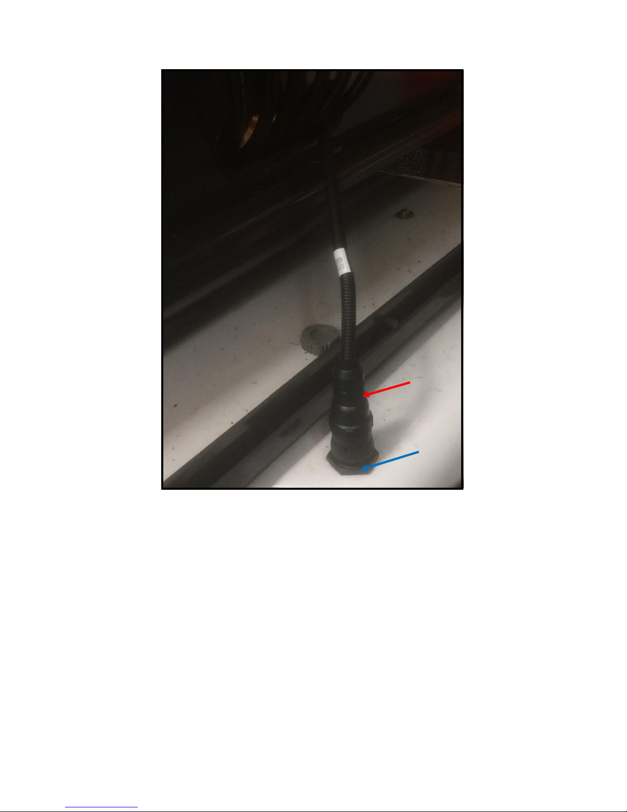
1. Open machine RH rear chassis panel to gain access to the PTO Needle Valve shown
above in Fig. 9.The needle valve is behing the splitter box
2. Screw needle valve completely out.
3. Check Charts above in Fig. 9 for adjustment data to suit the specific pump fitted to
the machine.
4. The needle valve needs to be setup to achieve approx. 40L/min to operate the Cityvac
attachment properly.
5. If the machine has a 35cc pump screw the needle valve in 6 ¾ turns (shown above).
6. If the machine has an 18cc pump screw the needle valve in 5 ¾ turns (shown above).
7. The machine will reach sufficient suction at 1250 RPM.
Once setup properly excessive acceleration will have no impact on the flowrate being sent
to the cityvac attachment.Figures above are guideline only and a flowmeter must be used
for accurate flow control.
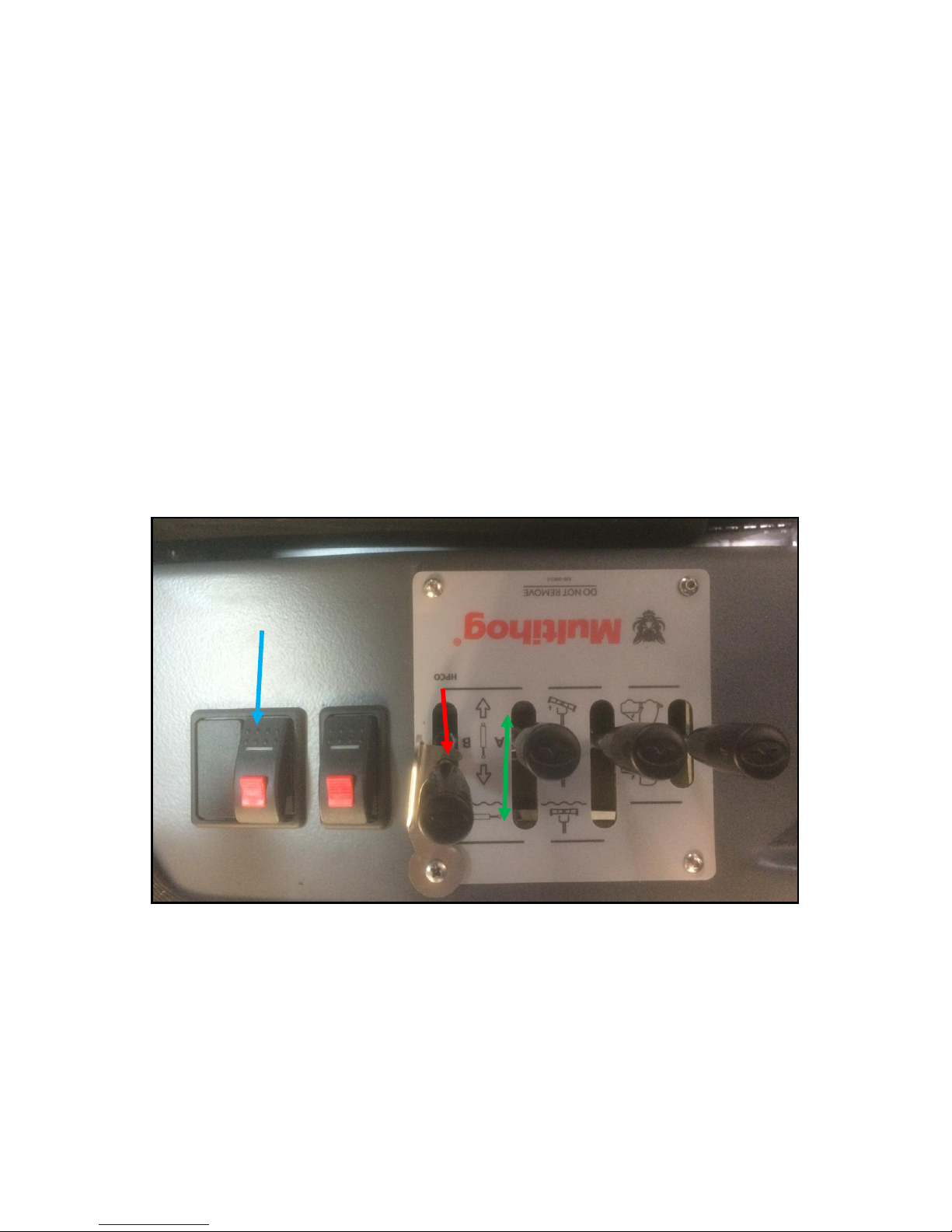
FIG. 10
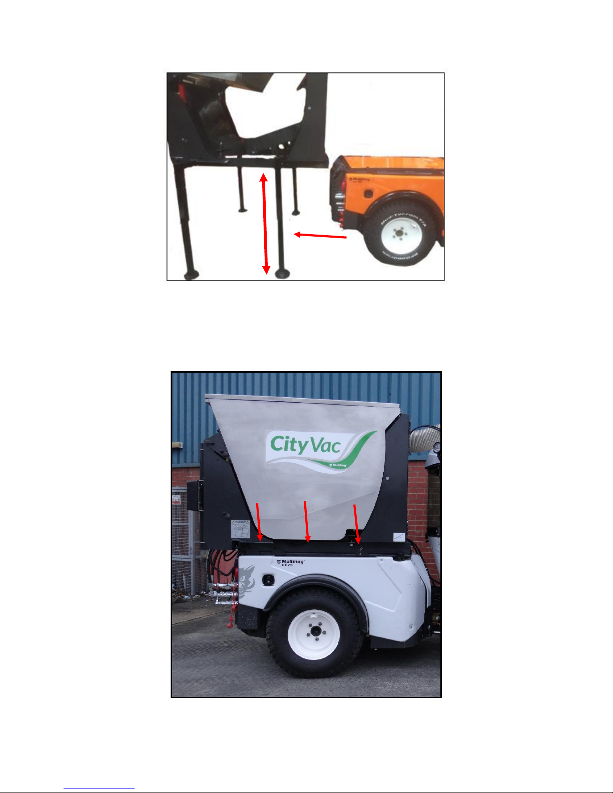
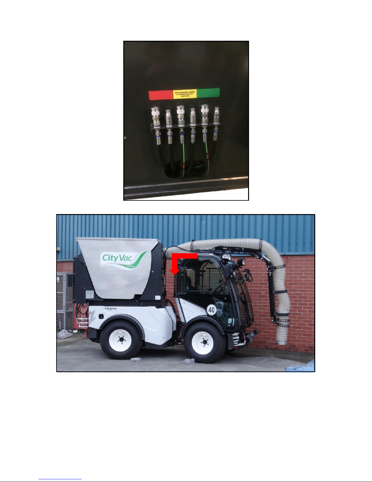
To operate the Cityvac follow the procedure outlined below.
1. (HPCO) Engage lever B outlined in red and lock in place to operate the high pressure
carry over and send oil supply to the valve block on the rear attachment. This
operates supplies oil to the trunk cylinders.
2. (FAN) Turn on the fan by pressure the PTO button highlighted in blue above.
3. (Tip Cyl.) To operate the Tipping Cylinders, use lever A highlighted in green above.