Multiple Awnings CARROUSEL Operating manual

MULTIPLE AWNINGS - 1701, de l’industrie - Beloeil ( uébec) - J3G 4S5
Tel : 450-446-4182 or 1-866-446-4182 - www.multipleawnings.com
Revision as of January 21 2009 Page 1 of 23
USER AND INSTALLATION MANUAL FOR
THE CARROUSEL AWNING
Warning:
PLEASE ENSURE SNOW AND ICE REMOVAL ON STRUCTURE
FOLLOWING A SNOW OR ICE STORM !
FAILURE TO FOLLOW THESE PROCEDURES COULD RESULT IN
INJURY !
•This user and installation guide is a complement to the installation
video. It is highly recommended that you carefully review these
instructions before installing your awning.
•Failure to do so could result in personal injury!

MULTIPLE AWNINGS - 1701, de l’industrie - Beloeil ( uébec) - J3G 4S5
Tel : 450-446-4182 or 1-866-446-4182 - www.multipleawnings.com
Revision as of January 21 2009 Page 2 of 23
INSTALLATION PROCEDURES FOR THE CARROUSEL AWNING
PAGE
TOOLS RE UIRED …………………………………………………………………..………………… 3
LIST OF COMPONENTS
Brackets and hardware ………………………………………………………………….. 4
Walls of structure and roof components …………………………………… 6
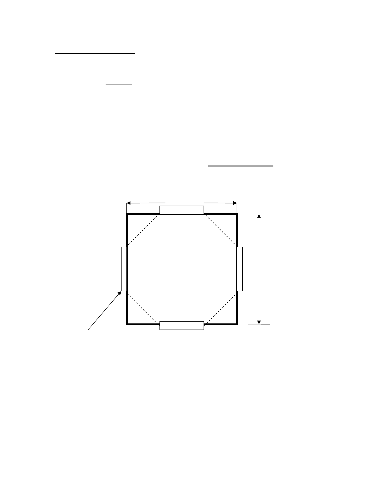
FLOOR PREPARATION ………………………………………………………………………………….. 8
ASSEMBLING THE WALLS…………………………………………………………………………… 9
Assembling the 7 large panels……………………………………………………………… 9
Building the 8th panel……………………………………………………………………………. 11
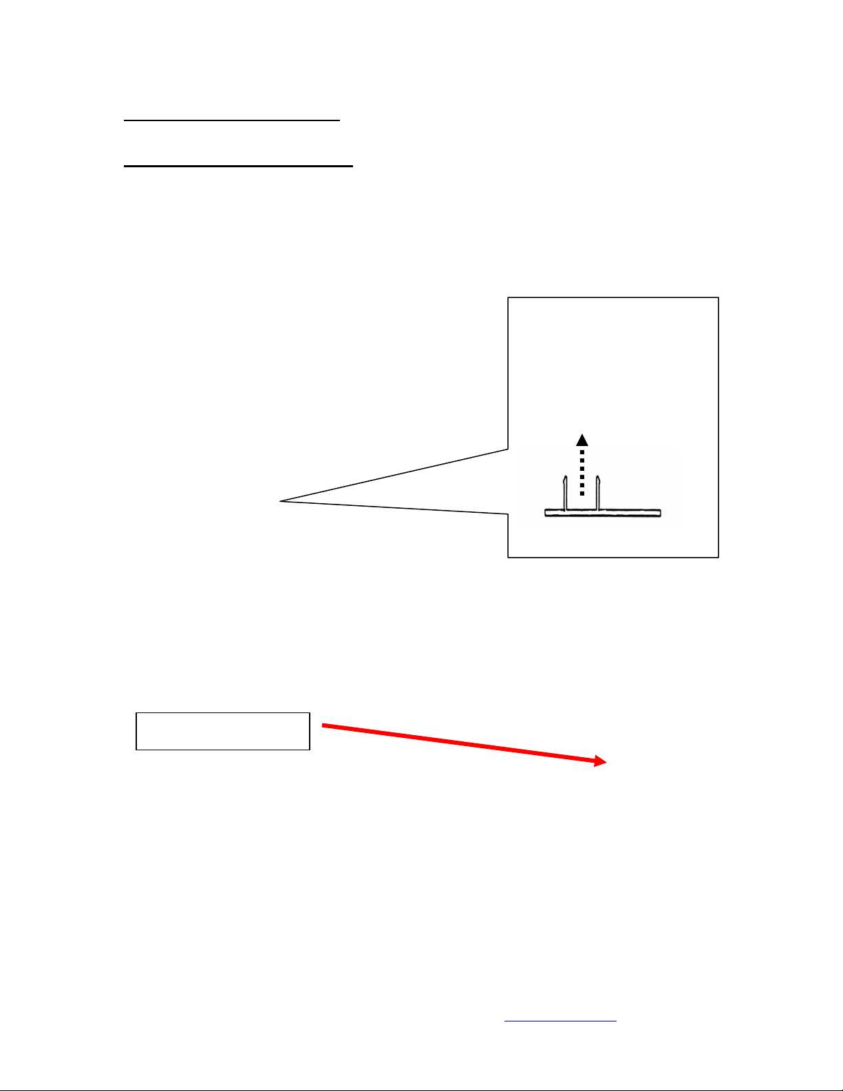
Anchoring the structure to the floor………………………………………………. 13
Installing exterior cappings ………………………………………………………………. 14
ASSEMBLING THE ROOF ……………………………………………………………………………… 15
INSTALLING THE VINYL ROOFING …………………………………………………………… 18
Unfolding the roof ……………………………………………………………………………….. 18
Tightening the vinyl roof using the Flash attachment system® … 19
THE DOOR INSTALLATION…………………………………………………………………………… 21

MULTIPLE AWNINGS - 1701, de l’industrie - Beloeil ( uébec) - J3G 4S5
Tel : 450-446-4182 or 1-866-446-4182 - www.multipleawnings.com
Revision as of January 21 2009 Page 3 of 23
TOOLS RE UIRED
1power drill
1drill bit 5/32’’ *
1 drill bit 3/16’’ for cement *
15/16’’ hex drill bit adaptor*
15/16’’ hex wrench *
1small pry bar
1square drill bit number 1
1square drill bit number 2 *
1 sharp knife (Exacto)
1pair of safety glasses
1metal file
1measuring tape
1chalk line
1rubber mallet
1pair of pliers
1caulking gun
4tubes of 100% silicone ( white or beige)
one 8 foot long ladder
one small 3 foot ladder
* tools included with shipment

MULTIPLE AWNINGS - 1701, de l’industrie - Beloeil ( uébec) - J3G 4S5
Tel : 450-446-4182 or 1-866-446-4182 - www.multipleawnings.com
Revision as of January 21 2009 Page 4 of 23
LIST OF COMPONENTS
Brackets and hardware:
5/16’’ self-tapping screw, ¾’’ long 100
Square roof cubes 8
V bracket for joining panels and anchoring to the floor 8
U bracket for fixing 4
#8 metal screws, square head, 1 ¼’’ long 40
22.5˚ bracket insert for joining upper panels together 8

MULTIPLE AWNINGS - 1701, de l’industrie - Beloeil ( uébec) - J3G 4S5
Tel : 450-446-4182 or 1-866-446-4182 - www.multipleawnings.com
Revision as of January 21 2009 Page 5 of 23
Template representing the leg of a panel 1
Roof crown 2
Cement screws 1 ¼’’ long 8
Door handle complete with screws and lock 1
#6 self taping screws for door hinges, 3/8’’ long 6
#8 pan socket metal screw for door assembly. ¾’’ long 6

MULTIPLE AWNINGS - 1701, de l’industrie - Beloeil ( uébec) - J3G 4S5
Tel : 450-446-4182 or 1-866-446-4182 - www.multipleawnings.com
Revision as of January 21 2009 Page 6 of 23
Door stopper 1
Walls of structure and roof components
Wall panels 78’’ x 56.5 ’’ 7
Side wall panels 78’’ x 10.75’’ 2
Door 1

MULTIPLE AWNINGS - 1701, de l’industrie - Beloeil ( uébec) - J3G 4S5
Tel : 450-446-4182 or 1-866-446-4182 - www.multipleawnings.com
Revision as of January 21 2009 Page 7 of 23
Upper door member 35” with its 2 outside cappings 1
Rafters 1.5’’ x 1.5’’ cube 8
2
1
1
–
Cornices
8
2 - Flash attachment systems 8
3
-
Simple interior
capping
20
4 – Exterior capping 8
3
4

MULTIPLE AWNINGS - 1701, de l’industrie - Beloeil ( uébec) - J3G 4S5
Tel : 450-446-4182 or 1-866-446-4182 - www.multipleawnings.com
Revision as of January 21 2009 Page 8 of 23
FLOOR PREPARATION
Before starting installation, make sure that the floor is level and structurally sound.
Note that the interior dimensions of the octagonal
CARROUSEL
are 136.5 inches.
The minimum overall size required for the platform is 142 inches, which includes an
extra inch all around the awning.
•Start by finding the center of the platform.
•Draw a square figure 136.5’’ x 136.5’’ in the center of the platform with a chalk
line ( see drawing below.)
•The doted lines represent the reference line for positioning the panels during
installation. Remember that these are interior dimensions of the
CARROUSEL
and the panels must rest on the outside of the doted line.
136.5’’
136.5’’
TOP VIEW OF THE FLOOR AREA
______ chalk line, CL : center line
panels
CL
CL

MULTIPLE AWNINGS - 1701, de l’industrie - Beloeil ( uébec) - J3G 4S5
Tel : 450-446-4182 or 1-866-446-4182 - www.multipleawnings.com
Revision as of January 21 2009 Page 9 of 23
ASSEMBLING THE WALLS
Assembling the 7 large panels
•Install the interior cappings on each panel with the use of a rubber mallet (this
step may have been done at the factory prior to shipment.) As a reference, the
screen is always facing outwards and the polymer windows facing inwards. There
are 2 interior cappings per panel. There are a total of 7 large panels and 2 small
side panels.
•Install the cornice on top of each panel with five 5/16’’ self-tapping screws. The
holes have been pre-drilled at the factory for your convenience. The cornice
must be flush and equidistant to each corner as seen in the picture below.
As an example :
Top view
Cornice must be flush

MULTIPLE AWNINGS - 1701, de l’industrie - Beloeil ( uébec) - J3G 4S5
Tel : 450-446-4182 or 1-866-446-4182 - www.multipleawnings.com
Revision as of January 21 2009 Page 10 of 23
•With the help of another person, place 2 panels upright, side by side on the
outskirts of the chalk line you drew on the floor. The angle of the cornices
should align perfectly.
•Install the Flash attachment system® on the cornice of each panel. To do so,
tilt the attachment system as shown so that it hitches on the lip of the cornice,
and then tilt it back straight.
•Slide a 22,5˚ bracket insert in the upper part of the Flash attachment system®
so that it joins both panels together.
•If the floor plan has been properly prepared, the panels should align perfectly.
The 22,5˚ bracket
insert will join both
panels together

MULTIPLE AWNINGS - 1701, de l’industrie - Beloeil ( uébec) - J3G 4S5
Tel : 450-446-4182 or 1-866-446-4182 - www.multipleawnings.com
Revision as of January 21 2009 Page 11 of 23
•With self-tapping 5/16’’ screws, fix the system as shown below. This will secure
both walls together.
Self-tapping 5/16’’ screws
•Repeat the above process until all 7 walls are attached together.
Building the 8th panel:
The 8th panel is composed of 2 side panels, a door and an upper door member
complete with its 2 outside cappings. To build this last panel:
•Lay both side panels with the polymer side facing upwards.
•Install a U bracket on the inside of each panel as shown on the picture below.
Use the template to ensure
that the U bracket is well
positioned

MULTIPLE AWNINGS - 1701, de l’industrie - Beloeil ( uébec) - J3G 4S5
Tel : 450-446-4182 or 1-866-446-4182 - www.multipleawnings.com
Revision as of January 21 2009 Page 12 of 23
•Once these 2 brackets are installed, slide in the upper door member in the U
brackets and fix it with self-tapping screws on both sides, then install the
cappings.
•Install the cornice on the top of the assembled panel as done with previous
panels and place the wall beside the other panels to complete the octagon.
•Install the Flash attachment system on the cornice, slide in the 22,5˚insert
to join the panels together. The walls of the CARROUSEL are now complete.
screw
screw

MULTIPLE AWNINGS - 1701, de l’industrie - Beloeil ( uébec) - J3G 4S5
Tel : 450-446-4182 or 1-866-446-4182 - www.multipleawnings.com
Revision as of January 21 2009 Page 13 of 23
Anchoring the structure to the floor
•Once the wall structure is complete and the panels have been secured together,
fix the structure to the floor.
•Make sure the walls are properly centered on the reference lines on the floor.
•Use the small V brackets provided and fasten the bottom of two panels
together with 5/16’’ self-tapping screws as shown on picture below.
•Once all panels are fixed together, the V brackets can be fixed to the floor.
Use the proper screws for the type of floor substrate you have.
Different floor types:
•WOOD FLOOR: use #8 square head screws 1 ¼ “ long.
•CEMENT FLOOR: you will need to pre-drill a 3/16” hole with an
impact drill and use cement screws 1 ¼” long.
•FIBERGLASS ON WOOD: make sure you use the length of screw
that is appropriate to your floor structure. Note that it is important
that you seal the hole with caulking when piercing the fiberglass or
else the fiberglass substrate may delaminate in the event of water
infiltration.

MULTIPLE AWNINGS - 1701, de l’industrie - Beloeil ( uébec) - J3G 4S5
Tel : 450-446-4182 or 1-866-446-4182 - www.multipleawnings.com
Revision as of January 21 2009 Page 14 of 23
Installing exterior cappings :
Once the structure is secured to the floor, the cappings can be installed. There are 8
exterior cappings that join the panels together.
•Place the capping as seen on drawing below. Note that on one of the sides, the
grooves is smaller. Make sure you start the alignment of the capping with the
opposite side. With a rubber mallet, hit the side of the capping forcefully until
the opposite end snaps into place.
•Start from the top of the structure and work your way down. If the walls have
been joined correctly, the cappings will snap in easily.
•Repeat the procedure until all 8 cappings are installed.
1
st
step
Insert one side of the exterior capping,
be sure that the screen is under the
capping before the second step
You may hit the capping
with the rubber mallet
where the arrow is
pointing. Be sure that
the screen of your
second panel is under
the capping.
2
nd
step Hit the capping on this side
Top view
Top view

MULTIPLE AWNINGS - 1701, de l’industrie - Beloeil ( uébec) - J3G 4S5
Tel : 450-446-4182 or 1-866-446-4182 - www.multipleawnings.com
Revision as of January 21 2009 Page 15 of 23
ASSEMBLING THE ROOF
•We have provided 8 small square cubes to be installed under the roof rafters to
hide the visible opening in the rafters and to be used as a support to these
rafters. Start to place 8 cubes in each corner, you will see the utility later.
•The rafters are now ready to be installed. Using #8 metal square head 1 ¼’’
long screws, fix the raters to the Flash attachment system®. Place the rafters
on the Flash attachment system® as seen on picture. The rafters must be
centered between the two cornices and must be slightly inwards to ensure no
shard edges will protrude. Pre-drill two 5/32’’ holes in the rafter, through the
Flash attachment system® and through the bracket inset.

MULTIPLE AWNINGS - 1701, de l’industrie - Beloeil ( uébec) - J3G 4S5
Tel : 450-446-4182 or 1-866-446-4182 - www.multipleawnings.com
Revision as of January 21 2009 Page 16 of 23
•Repeat these steps until all 8
rafters are in position. With
the help of small square cubes,
each rafter should be standing
up.
•You are now ready the fix
the roof crown. Insert
each rafter in the roof
crown and separate the two
crowns to be sure that
there is one to the top and
another to the bottom. Fix
it with #8 metal square
head 1 ¼’’ long screws.
Pay attention to the small square
cube, it must be placed under the
rafter like a support, it will enable
the rafter to stand up by itself.

MULTIPLE AWNINGS - 1701, de l’industrie - Beloeil ( uébec) - J3G 4S5
Tel : 450-446-4182 or 1-866-446-4182 - www.multipleawnings.com
Revision as of January 21 2009 Page 17 of 23
•The aluminum structure is now complete and ready to receive the vinyl roof.
You must file down
any rough corners to
prevent damage during
installation.
CAUTION:
It is important to file down any rough or cutting edges found on the Flash
attachment system® and on the rafters. If this is not done properly, the vinyl
roof may be damaged during installation or later on.

MULTIPLE AWNINGS - 1701, de l’industrie - Beloeil ( uébec) - J3G 4S5
Tel : 450-446-4182 or 1-866-446-4182 - www.multipleawnings.com
Revision as of January 21 2009 Page 18 of 23
INSTALLING THE VINYL ROOFING
Unfolding the roof:
•The vinyl roof has been specially folded to facilitate the installation so leave it
folded until further notice.
•With the help of someone inside the CARROUSEL, place the vinyl roof on top of
the roof structure and pull the pointy part of the vinyl roof up towards the
center of the awning i.e. on the roof crown.
•Unfold the vinyl roof until you get half of the roof covered. Make sure you
match the sewing seems with the rafters. No sewing seem should be visible from
inside the awning.
•Unfold the other half of the vinyl roof by flipping it over to the other side of
the structure making sure the corners are well in place and the sewing seems
are well aligned. Verifying this is mandatory before beginning the next step.
Pointy part unfolding

MULTIPLE AWNINGS - 1701, de l’industrie - Beloeil ( uébec) - J3G 4S5
Tel : 450-446-4182 or 1-866-446-4182 - www.multipleawnings.com
Revision as of January 21 2009 Page 19 of 23
Tightening the vinyl roof using the Flash attachment system®
•Once the vinyl roof is properly centered
and the sewing seems are well aligned
with the rafters, fold back partially
each corner of the vinyl roof over the
cornices as shown.
•The white Fabreen® strip sewn
on the vinyl can now be inserted
in the Flash attachment system®
so that tension can be put on the
vinyl. To do so, fold the PVC strip
in the grove of the Flash
attachment system® as shown
below. Follow this procedure until
all 8 sides are inserted.
•With a sharp knife, cut a 3 inch long slit
in the Fabreen® to access the bolts of
the tensioning system. There are 2
bolts per system, one on each
extremity.
the grove of
the Flash
atta hment
system®
the PVC strip
Cut over the
bolt to get it

MULTIPLE AWNINGS - 1701, de l’industrie - Beloeil ( uébec) - J3G 4S5
Tel : 450-446-4182 or 1-866-446-4182 - www.multipleawnings.com
Revision as of January 21 2009 Page 20 of 23
•You are now ready to start applying tension to the Flash attachment system®.
With a 5/16’’ ratchet key, tighten the 2 screws on each system. Make sure you
tighten both bolts so that the tension is distributed equally.
•It is important to alternate this tightening procedure on all 8 sides of the roof.
We recommend that you apply tension on opposite sides to ensure that the
tension is well balanced.
•Once you get the correct tension on the roof, fold down the corners of the vinyl
roof to complete the installation.
When the
Fabreen®
is cut
A 5/16” rat het key
to tight the s rews
Table of contents
Other Multiple Awnings Accessories manuals