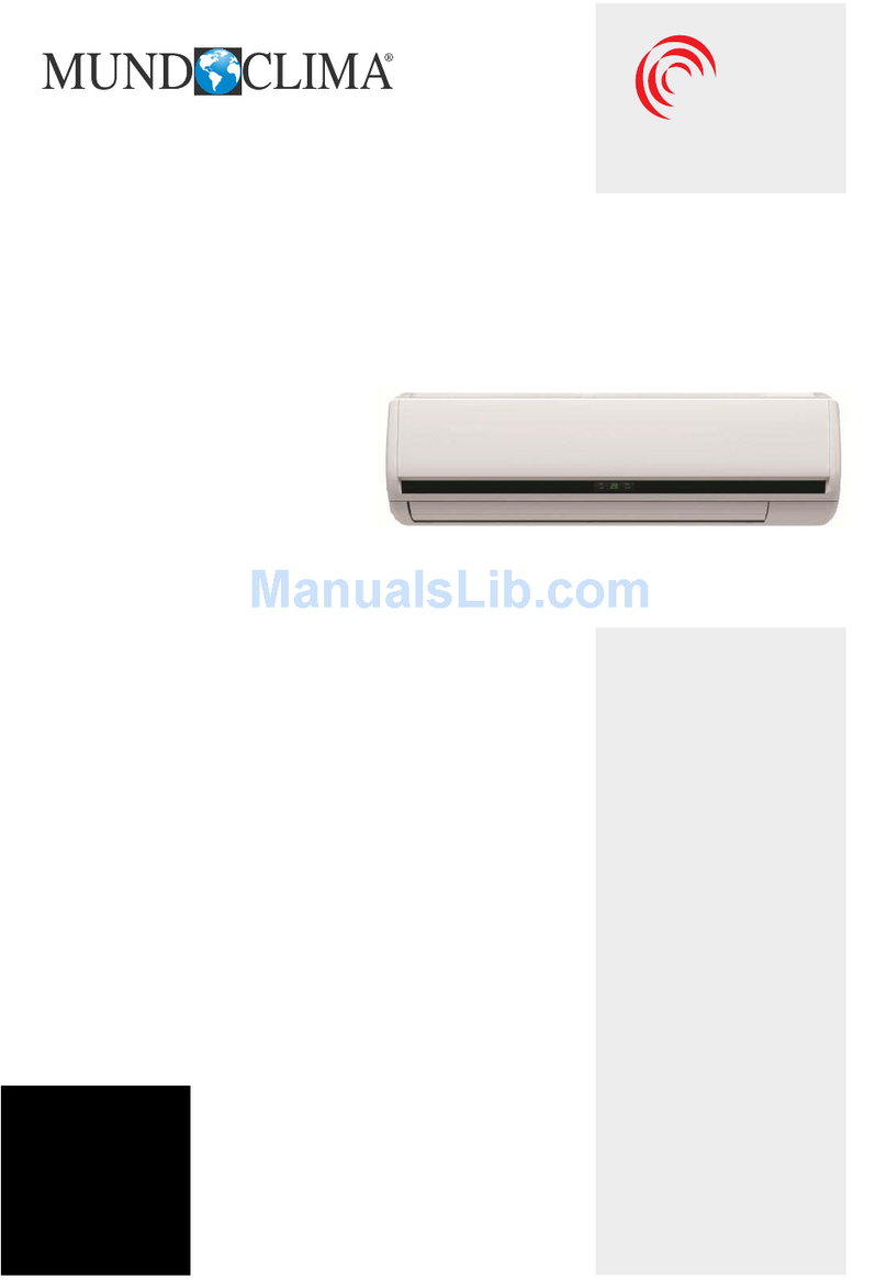
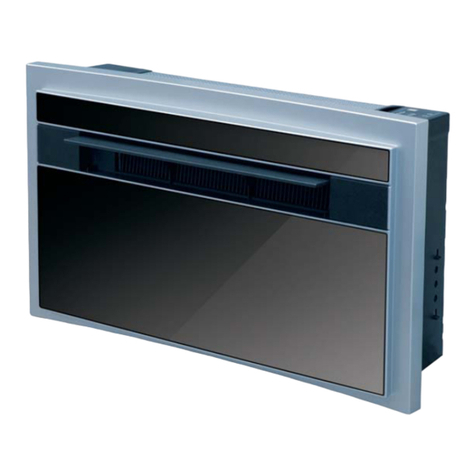
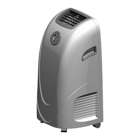
mundoclima CL23269 User manual
Other mundoclima Air Conditioner manuals

mundoclima
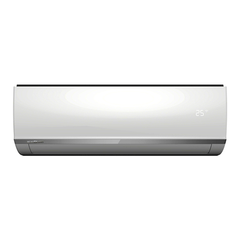
mundoclima MVD CL23130 User manual
mundoclima
mundoclima H6M SERIE User manual
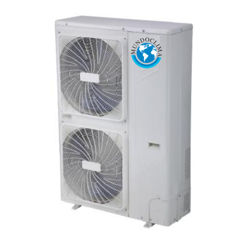
mundoclima
mundoclima AEROTHERM V17 Quick start guide
mundoclima
mundoclima CL23330 User manual
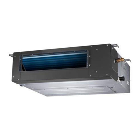
mundoclima
mundoclima MUCR-H6 Series Installation instructions
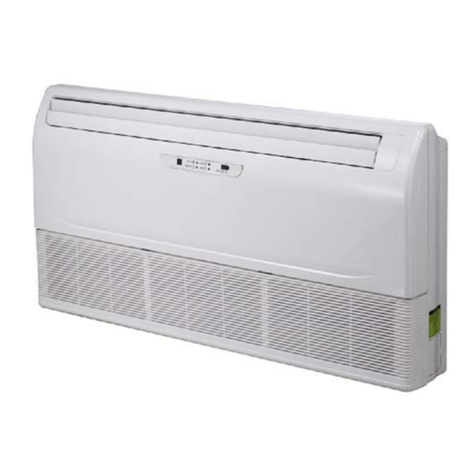
mundoclima
mundoclima MVD-36DLDN1 User manual
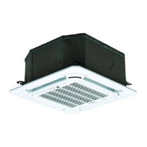
mundoclima
mundoclima MUCS-W7 User manual
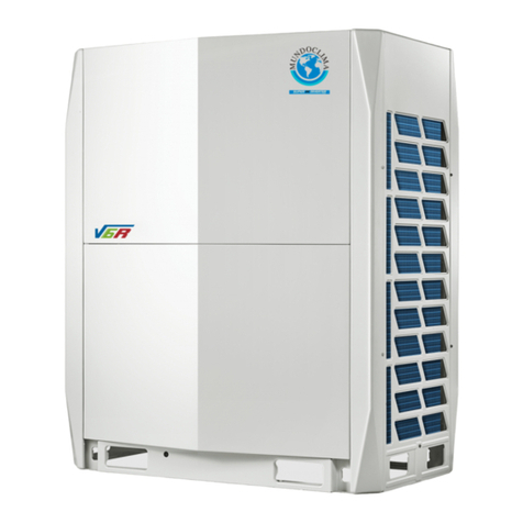
mundoclima
mundoclima MAXI MVD V6R Series User manual
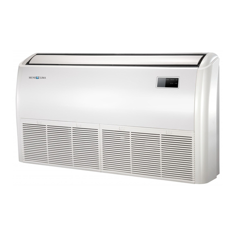
mundoclima
mundoclima MUSTR-H6 Installation instructions
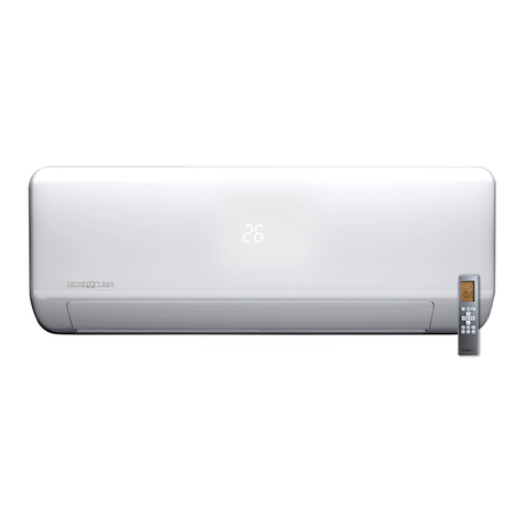
mundoclima
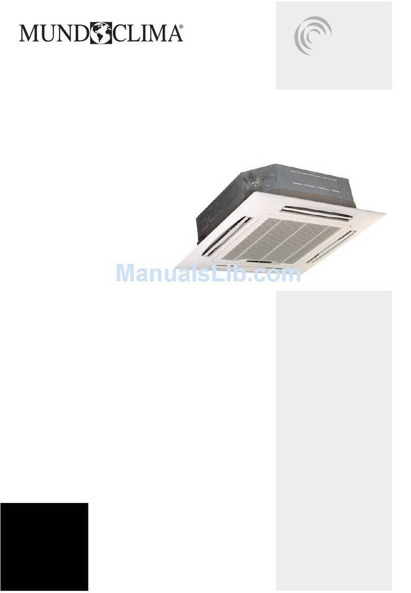
mundoclima MUPR-H10X Series Installation instructions
mundoclima
mundoclima CL23320 User manual

mundoclima
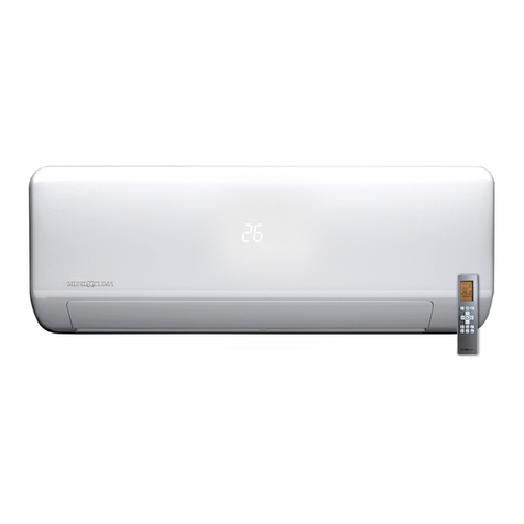
mundoclima WF105 Installation instructions
mundoclima
mundoclima H10X Series User manual

mundoclima
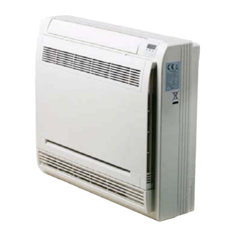
mundoclima MUP-W7 User manual
mundoclima
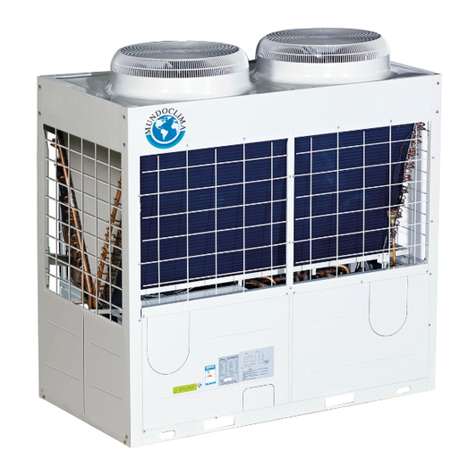
mundoclima MVD DC2 Series Installation instructions
mundoclima
mundoclima MUEN-H6 Series Operating instructions
mundoclima
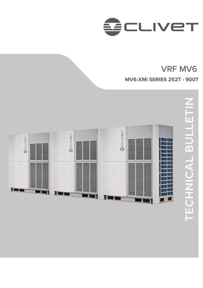
mundoclima MV6-XMi Series Service manual
mundoclima
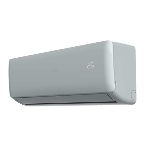
mundoclima H5A Serie User manual
mundoclima
mundoclima MUP-W7 Operating instructions
mundoclima
mundoclima MUPR-09-H11 Installation instructions
Popular Air Conditioner manuals by other brands

Fujitsu
Fujitsu ASYG 09 LLCA installation manual

York
York HVHC 07-12DS Installation & owner's manual

Carrier
Carrier Fan Coil 42B Installation, operation and maintenance manual

intensity
intensity IDUFCI60KC-3 installation manual

Frigidaire
Frigidaire FAC064K7A2 Factory parts catalog

Sanyo
Sanyo KS2432 instruction manual

Mitsubishi Electric
Mitsubishi Electric PUHZ-RP50VHA4 Service manual

Panasonic
Panasonic CS-S18HKQ Service manual

Panasonic
Panasonic CS-E15NKE3 operating instructions

Gree
Gree GWH18TC-K3DNA1B/I Service manual

Friedrich
Friedrich ZoneAire Compact P08SA owner's manual

Daikin
Daikin R32 Split Series installation manual

