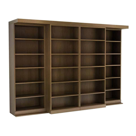
Murphy ELITE ABF-M User manual

$15.00
ELITE
Aluminum Bed Frame & Mechanism
Models ABF-M and ABF
INSTRUCTIONS
Available in:
●Single/Twin*
●Double/Full*
●Queen
●King
* Extra length available
Established in 1975
TOLL FREE 1-800-667-6336
PHONE: (604) 576-7880 • FAX: (604) 576-7867
Websites: murphybeds.com • spacebeds.com • wallbedco.com • tiltawaybeds.com

CONGRATULATIONS
on your purchase of Murphy Wall-Beds’
Elite patented aluminum bed frame, lift
mechanism, stiffener and folding leg
system, designed to International ISO
9002 standards to exceed both
residential and commercial
specifications.
Other Quality Products:
•Economical Supreme Steel Bed Frame &
Mechanism Systems
•Side-Tilt Models
•ETA Bed Cabinets & Side Cabinets
•Do-It-Yourself Mechanism Systems & Plans
•Extended legs
•Super Springs – Support 20% more weight
•Murphy Hidden Bed
•Murphy Bed Closet Hardware
Contents
Package Contents & Equipment Checklist 3
Hardware Identification Key 4
Bed Cabinet Assembly Instructions 6
Securing the Bed Cabinet 8
Installing Springs in Lift Mechanisms 9
Mounting Lift Mechanisms 10
Assembling the Bed Panel Unit 11
Installing the Bed Panel Unit 14
Attaching Handles & Legs 16
Installing Mattress & Mechanism Covers 17
Aluminum Bed Frame Cut List 18
The Murphy Wall-Bed Lifetime Guarantee
Retail Residential Term
Lifetime Guarantee on Hardware ●5 Year Structural Guarantee on Cabinetry
Commercial Term
Lifetime Guarantee on Hardware ●2 Year Structural Guarantee on Cabinetry
2
Murphy Wall-Beds has been proudly doing business since 1975 under the names Tilt-Away Beds of America®, Tilt-Away Beds of Canada® and
Murphy Wall-Beds of Canada®, which are all registered trademarks of Murphy Wall-Beds Hardware Inc. Copyright © by Murphy Wall-Beds Hardware
Inc. These instructions are issued for the exclusive use of the original customer who purchased this product under any of the trademarks or Internet
domains held by MURPHY WALL-BEDS HARDWARE INC. Using the component parts for or representing and selling this product as a ‘MURPHY
BED’ in Canada or ‘TILT-AWAY BED” world-wide may be interpreted as both trademark and copyright infringement. No part of this publication may be
reproduced, storedin or introduced into a retrievalsystem, or transmitted, in any formor by any means without prior written permission.

Contents of Mechanism & Aluminum Bed Frame Boxes
Bag #14
Qty. Item
2 L/R Panel Guards
2 ½" x ¾" Leg Stops
6 5/16" black Hole Plugs
Assembling Frames, Panel Guards & Leg Stops:
Qty. Item
4 1" x 1" x 1¾" 4-hole corner brackets
10 3/16″x ½" black flathead Phillips screws
4 3/16″x ½" black trusshead Phillips screws
2 3/16″x 1¼" black flathead Phillips screws
16 3/16″Nylock hexagon nuts
4 5/16" x ¾" hexhead machine bolts
2 Allen key sockethead bolts
6 5/16" Nylock hexagon nuts
Attaching Legs to Crossbar:
Qty. Item
2 ¼" x ¾" hexhead machine screws
2 ¼" x ½" (OD) star washers
Qty. Item
2 Lift Mechanisms, Left/Right (L/R)
18 Lift Mechanism Springs
2 Lift Mechanism Safety Cover Plates (L/R)
1 Foot Frame with gold label
1 Head Frame
2 Side Frames
1 Stiffener (not used in Single/Twin systems)
1 pr. Velcro Straps
1 13" Plastic Pipe
2 Legs, L/R, with the following attached:
1 - ¾" x 1¼" (OD) Lexan plastic washer
1 –
5/16" x 1½" (OD) flat washer
1 -
5/16" x 1½" (OD) flat washer
1 -
5/16" Nylock hexagon nut
1 Leg Crossbar with end-plugs attached
Bag #16
Attaching Side Panels to Top Stretcher:
Qty. Item
6 Confirmat screws
6 Confirmat screw caps
Attaching Kick, Headboard, Bottom Stretcher:
Qty. Item
10 1″x 1″x 1¾″assembly brackets
40 #8 x ¾″panhead screws
Bag #10
Qty. Item
1 Warning Label
Securing Cabinet to Wall:
Qty. Item
2 2" x 2" L brackets
6 #8 x 2" flathead wood screws
6 #8 x ¾" flathead wood screws
For Top Stretcher:
Qty. Item
3 ¼" rounded bumper buttons
For Leg Bumpers:
Qty. Item
2 3/8″flat bumper buttons
Mounting Mechanism to Side Panel:
Qty. Item
8 5/16" x 1¼" flathead slot machine screws
2 ¾" hexagon cam washers
2 5/16" x 7/8" (OD) flat washers
8 5/16" plain hexagon nuts
Attaching Mechanism Covers:
Qty. Item
4 4mm x ¼" flathead slot machine screws
Bag #15
Attaching Velcro Straps:
Qty. Item
2 3/16″x ¾″(OD) flat washers
Attaching Frames & Stiffener to Bed Panels:
Qty. Item
110 #8 x
5/8″panhead screws
3

Attaching Handles & Legs
NOTE: To give you flexibility in installing the recommended
handles, the Bed Face Panels are now drilled from the back side
to within 1/8″of the front of the panels. This gives correct position
for our stock handles, or you may drill custom holes.
HELPFUL HINT: When drilling through your panels, clamp a
scrap piece of plywood to the face side to prevent chipping or
damage of the finished, visible faces.
Before You Begin
Visit our website at
www.murphybeds.com to view
Video Clip #7, Attaching the Legs
& Mechanism Covers. These last
few steps will be much easier if
your assistant is on hand to hold
the Panel that opens.
1. Attach your personal choice of handles to the face of the Bed Panel Unit using the screws provided with the
handles. Keep in mind that the Unit has a 3″Stiffener joining the Panels, so don’t drill the holes within 2″of
the Unit’s center seam. To minimize the pull required to open the bed, locate the lowest part of the handles
not more than 36″from the top of the Unit.
2. Pull the panel unit open to a convenient working height. Remove the 5/16" Nylock hexagon nuts and the 5/16" x
1½"(OD) flat washers from the legs, leaving the thin black plastic washers in place. Insert the leg screws
through the frames, replace the washers and nuts, and tighten the nuts.
3. Pivot both legs upward and position the crossbar between the legs. Place a ¼" x ½"(OD) star washer on one
of the ¼" x ¾" hexhead machine screws, thread the screw through the leg hole and screw into the crossbar,
as in Figure 11. Do not over-tighten. Repeat the process on other side.
Leg stop in place.
Figure 11. Installing the Legs & Crossbar, right leg view.
4. Attach the two 3/8" flat Bumper Buttons to the surface of the Bed Panels where the legs, when folded up, will
contact the Panels. See Figure 11 for further detail. Gently close the bed.
IMPORTANT: To avoid damaging the front edge of the Top Stretcher, be sure to fold up the legs before
closing the bed.
16

Installing Mattress and Mechanism Covers
1. Have the mattress on hand. Open the bed, fold down the legs and hold the bed fully open by placing one foot
on the Crossbar. Put the mattress in place, ensuring that it lies completely within the Frame. The added
weight of the mattress should now hold the bed down.
Note: Using a thin coil or light-density foam mattress less than 9" thick may
require a reduction in the number of springs required to balance the bed.
There is a slight chance that you may feel the stiffener through the mattress.
Should this be the case, simply fill the spaces between the Stiffeners and the
Frames with ½″to ¾″Styrofoam or Foamboard, both of which are very light
and will not affect the balance of the bed.
2. Clip the black plastic Mechanism Covers on each Lift Mechanism so that the tabs hook into the indents on the
back plates. Secure with the four 4 mm x ¼" flathead slot machine screws.
3. Trim the Velcro straps so that they overlap a minimum of 12" and lightly singe the loose ends with a match to
seal the nylon. The bed will close fully made up with the straps holding the pillows in place. If you installed the
correct number of springs in the Lift Mechanisms, the bed should float at an angle of approximately 45º.
IMPORTANT! Before using the bed, allow at least 24 hours (from the time you attached the Frames
and Stiffener to the Bed Panels) for the adhesive tape to cure properly. Allow bed to remain down for
24 hours by placing extra weight on the bed to allow the springs to adjust to their established
p
lacement and tension.
17

Aluminum Bed Frame Cut List
Single Twin Bed (Mattress size 39" x 75" x 10" thickness)
Overall Cabinet Dimension: 44½"W x 80 1/16"H x 15 7/8" D
Protrusion from wall to foot bed: 84½"
# of pieces Description Width Length Material
1 BED PANEL 42
5/8" 77
5/16" ¾" Plycore
2 SIDE PANELS 15
7/8" 80
1/16" "
1 HEADBOARD 14
7/8" 43" "
1 TOP STRETCHER 14
7/8" 43" "
1 BOTTOM STRETCHER 6" 43" "
1 KICK 1
7/8" 43" "
Double/Full Bed (Mattress size 54" x 75" x 10" thickness)
Overall Cabinet Dimension: 59½"W x 80 1/16"H x 15 7/8" D
Protrusion from wall to foot bed: 84½"
# of pieces Description Width Length Material
2 BED PANEL 28 ¾" 77 5/16" ¾" Plycore
2 SIDE PANELS 15
7/8" 80
1/16" "
1 HEADBOARD 14
7/8" 58" "
1 TOP STRETCHER 14
7/8" 58" "
1 BOTTOM STRETCHER 6" 58" "
1 KICK 1
7/8" 58" "
Queen Bed (Mattress size 60" x 80" x 10" thickness)
Overall Cabinet Dimension: 65½"W x 851/16"H x 157/8" D
Protrusion from wall to foot bed: 89½"
# of pieces Description Width Length Material
2 BED PANEL 31 ¾" 82 5/16" ¾" Plycore
2 SIDE PANELS 15
7/8" 85
1/16" "
1 HEADBOARD 14
7/8" 64" "
1 TOP STRETCHER 14
7/8" 64" "
1 BOTTOM STRETCHER 6" 64" "
1 KICK 1
7/8" 64" "
King Bed (Mattress size 78" x 80" x 10" thickness)
Overall Cabinet Dimension: 83½"W x 851/16"H x 157/8" D
Protrusion from wall to foot bed: 89½"
# of pieces Description Width Length Material
2 BED PANEL 40 ¾" 82 5/16" ¾" Plycore
2 SIDE PANELS 15
7/8" 85
1/16" "
1 HEADBOARD 14
7/8" 82" "
1 TOP STRETCHER 14
7/8" 82" "
1 BOTTOM STRETCHER 6" 82" "
1 KICK 1
7/8" 82" "
Copyright © by Murphy Wall-Beds Hardware Inc.
18
This manual suits for next models
1
Table of contents
Other Murphy Indoor Furnishing manuals
Popular Indoor Furnishing manuals by other brands

Furniture of America
Furniture of America CM4265DK-E Assembly instructions

Meblik
Meblik XA.13 manual

Stander
Stander 8900 Series instructions

URBAN OUTFITTERS
URBAN OUTFITTERS MAIA CONSOLE Assembly instructions

Forte
Forte Bohol BHLB01 Assembling Instruction

Habitat
Habitat AFRICA AFRI-FC-04-A quick start guide