Bed Cabinet Assembly Instructions
1. Cut panels exactly as specified in the Cut List
located on page page 5(reg leg), page 20
(extended leg) and page 21(Long Leg) of these
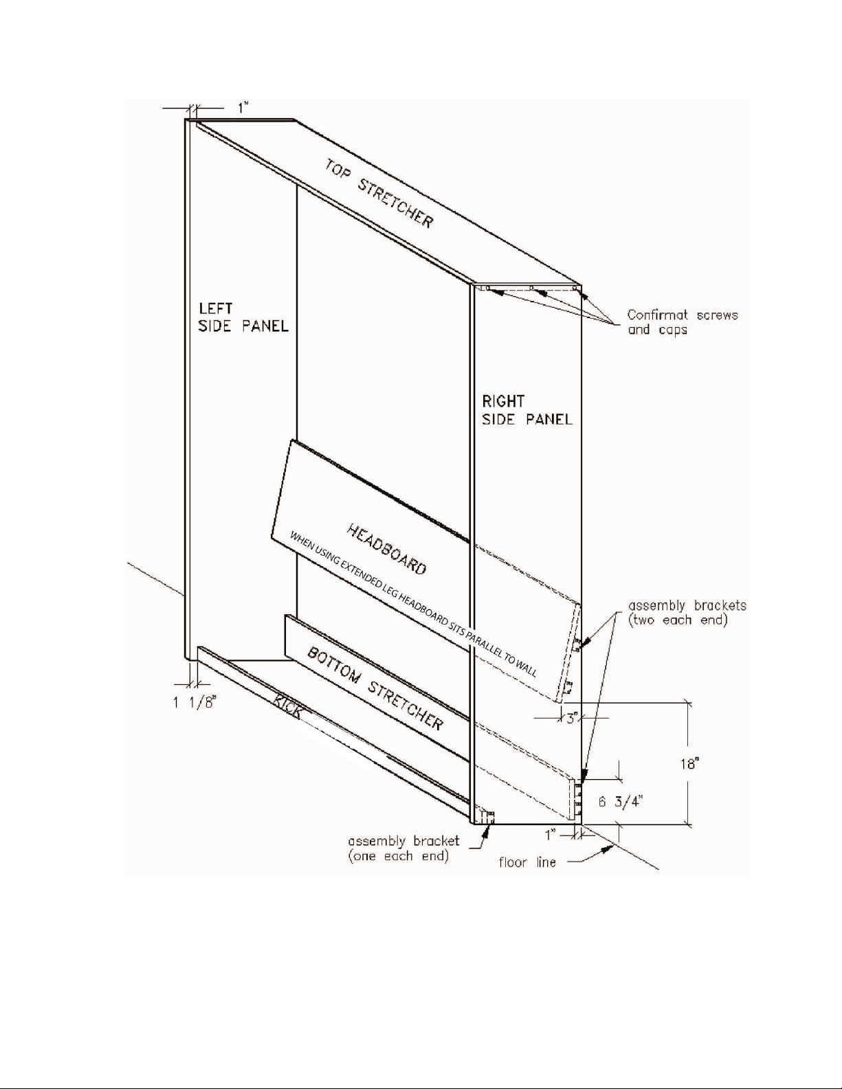
instructions. As you cut each piece, identify it using
a pencil, as indicated in Figure 1. Label the Bed
Panels (not shown in Figure 1) BED PANEL. You
will use these names throughout the instructions to
reference the particular items.
2. Clean and/or sand pieces. Tape the following
edges that will be exposed after construction:
TOP STRETCHER & SIDE PANELS –front
edges
HEADBOARD –both long edges
BOTTOM STRETCHER –top edge
KICK –both long edges (to prevent bowing)
FACE PANELS –all four sides
Helpful Hint: The simplest method is to use pre-
glued, iron-on tape appropriate for the construction
material you are using.
3. Make a small mark on the inside of each Side
Panel, 3″ from the back and 18″ from the bottom.
From this mark measure up and back 147/8″ to the
back edge of the Side Panels. Make another mark
and pencil a line to indicate the back of the
Headboard Position.
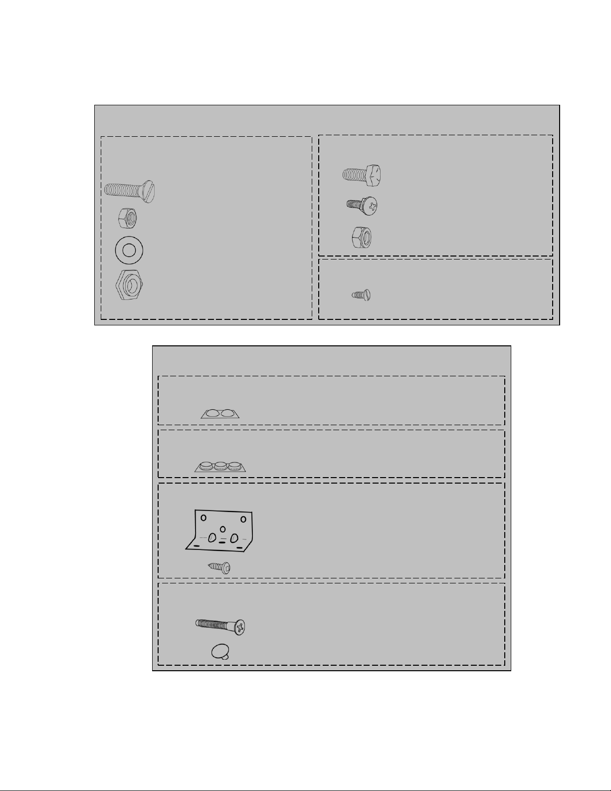
4. Attach 1″ x 1″ x 1¾″ assembly brackets to the
Headboard, Bottom Stretcher and Kick as per
Figure 1. Note that you must set the top brackets
of the Headboard low enough so they do not
protrude beyond the back of the cabinet. If you will
be notching out Side Panels to accommodate a
baseboard, attach the Bottom Stretcher. Brackets
to the front side of the notches.
5. Accurately mark the Lift Mechanism mounting
holes on the inside of each Side Panel. See
Figure 2 for the layout of these holes. When
drilling the holes, first drill a 1/16″ hole with a 5/16″
bit. Countersink (5/8″ diameter) each hole on the
outside of the panels, just deep enough for the
head of the 5/16″ x 1¼″ flathead slot machine screw
to sit flush with the surface. (You can sand and
paint the machine screws’ heads to match your
Cabinet finish.)
6. Align the back edges of the Top Stretcher and the
Side Panels and clamp with 72″ bar clamps. Using
a 3/16″ (5mm) bit, drill three Confirmat screw holes
per side to a depth of 2″. Keep the outer holes 1″
away from the front and back edges of the Top
Stretcher. Center the third hole between them. Un-
clamp and re-drill the Side Panel (shank) holes
using a 9/32″ (7mm) drill bit. Do not countersink
these holes. See Figure 3.
7. Prior to assembling the Bed Cabinet, you may
wish to apply your choice of finish to the individual
pieces.
8. You can now begin assembling the Bed Cabinet –
if possible, do this in the room where you will
install the Bed Cabinet. Refer to Figure 1 for
positioning and dimensions. Prop up one Side
Panel and the Top Stretcher on their back edges
and attach with Confirmat screws. Attach other
Side Panel. Press-fit the Confirmat caps.
Helpful Hint
Before you begin, you may wish to visit our website at
www.murphybeds.com to view the Quick Time
Video showing the assembly of an Elite Aluminum
Frame. Please note that your Supreme Steel Frame
does not require the adhesive tape on the frame and
stiffeners, and the Supreme Steel stiffeners are
attached side to side.
Please Note:
Be sure to use the section of the Bed Frame Cut List
that corresponds to the size of the bed that you are
constructing.
Do not glue the Bed Cabinet together.