Music Thing Modular SimpleEQ Manual

Music Thing Modular
SimpleEQ
Build Doc
(0805 version)
MTM SimpleEQ 0805 build doc v1.1 Page 1

Useful inks
The latest version of this doc and OM can always be found at http://thonk.co.uk/documents/eq/
A build thread on the Muffwiggler DIY forum can be found at this URL
Quickstart
If you're new to building with SMD components, skip to the detailed notes on the next page.
If you're an experienced SMD builder you'll probably want to skip the lengthy notes below, so
here's some things that will probably save you time when you're building this project.
•A detailed OM can be found on the last page of this document.
•The silk on the PC for diodes D1 & D2 does not show their polarity. The cathode for both
components is aligned towards the nearest edge of the PC , away from the power header.
There are pictures on page 16 that show this.
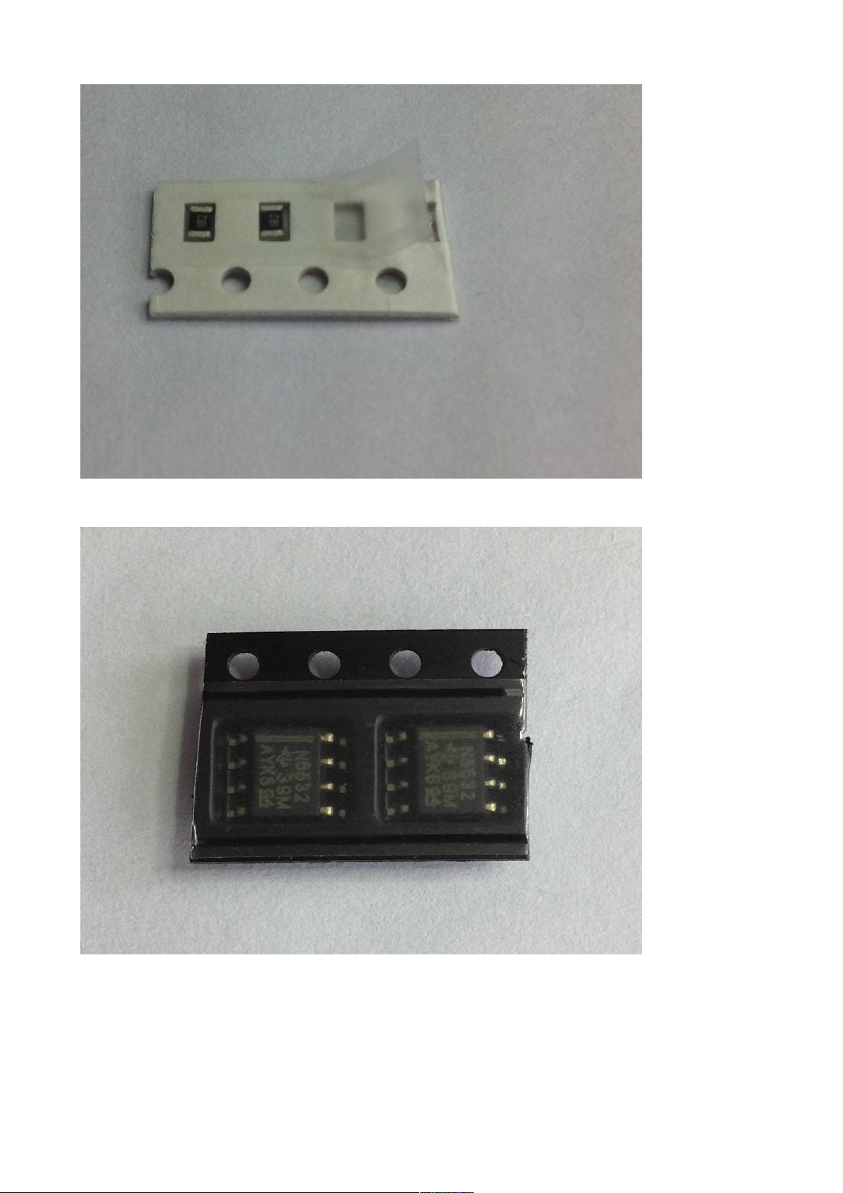
•The op-amps might not have pin 1 indicated by an adjacent dimple/dot in the package, or by
a semi-circular indentation at the end nearest pin 1/pin 8, as is common with through hole
ICs. SMD devices often have one of the longer sides with a sloped face, the other with a
vertical face. If you have such a device, pin 1 is the left-most pin of the side with the sloped
face when the device is pointing upwards. The silk screen on the PC shows both the
traditional circle next to pin 1 and also a line to indicate the orientation for devices with a
sloped face. Tthere are pictures on page 18 that show this.
•The suggested build order is to start with the components that have the lowest profile &
work upwards, so thats
◦resistors
◦non-polarised capacitors
◦diodes & PTC fuses
◦ICs
◦electrolytic capacitors
◦through hole components and panel
•It's suggested that you regularly stop to clean and inspect your work. It's much easier to re-
solder a joint when the board doesn't have the jacks and knobs fitted.
MTM SimpleEQ 0805 build doc v1.1 Page 2

Recommended Tools
To work with surface mount devices, such as in this kit, it's a good idea to have the following tools
to hand:
•Soldering iron with a small tip. A 1-2mm chisel or point tip is preferable.
•Fine gauge solder. Ideally 0.7mm or less.
•Solder wick. This is almost essential for removing excess solder, especially when soldering
the ICs.
•Flux pen. This isn't essential for a kit like this with only 2 x 8-pin IC's, but it does make
soldering some components much easier.
•Fine point tweezers. These are essential for handling surface mount components.
•Magnifying glass or jewellers Loupe. You'll need some method of inspecting solder joints.
Magnification of 10x is recommended.
•Soft haired brush and PC cleaner for removing flux. The type of cleaner will depend the on
the solder you use. Isopropyl alcohol usually works well.
MTM SimpleEQ 0805 build doc v1.1 Page 3

Introduction to working with Surface Mount
Components
This section isn't meant to be a definitive guide to working with surface mount technologies. You'll
find plenty of tutorials online for that. This is intended to provide some tips as to how to approach
building this kit.
Many surface mount components are supplied in tape packaging. For passive components such as
resistors and capacitors, the tape is usually made of cardboard, whilst semiconductors, such as ICs,
transistors, diodes etc will be in a anti-ESD plastic. Most tapes will have a layer of clear plastic film
over one side. To remove the device, the easiest way is to carefully peel away the plastic film with a
pair of tweezers or fine nosed pliers. Take care when you remove this film. These components are
small, and it's easy to lose them. It's a good idea to remove them from the packaging & place them
into a bowl or other similarly shaped container, then pick them from there as you place them onto
the PC .
MTM SimpleEQ 0805 build doc v1.1 Page 4
Illustration 1: SMD resistors supplied in tape

Install one component type & value at a time. Many of these components are not labelled with their
values, so don't mix them up. Finish one component type & value before proceeding to the next.
Don't rush. Regularly inspect your work with the magnifying glass or loupe. Clean your work as
MTM SimpleEQ 0805 build doc v1.1 Page 5
Illustration 2: SMD resistors in tape showing plastic cover partially peeled away
Illustration 3: SMD IC's in tape packaging

you go. You'll find it much easier to inspect your work with the solder flux residue removed.
There's many useful resources online for tutorials on working with surface mount devices. The
techniques here suggested here are one way to solder surface mount devices. As you become more
familiar with working with this technology, you may find other ways of working that you prefer.
So, to the kit ...
MTM SimpleEQ 0805 build doc v1.1 Page 6

The Build
Lets start with the resistors.
Find the component tape strip that's marked “10K”. As described above, open up the tape strip by
removing the clear film cover, tipping it's contents into the bowl. There will be 4 resistors. One side
will probably be a darker colour than the other. The darker side may be marked with it's value “103”
(10 x 103 or 10,000 or 10K). Whilst it doesn't matter which side of the component you have facing
upwards, it's usual to have the side with the value pointing upwards. As resistors are not polarised it
doesn't matter which end of the resistor is soldered to which pad on the PC .
efore we actually solder the first of the resistors, lets take some time to actually see how the
resistor will be located on the PC . Place the PC on a flat surface. Find the location of the first of
the 10K resistors, R1. It's over towards one side of the board. Notice that the PC has 2 pads for the
component, and white silk screening around the outside of the pads.
MTM SimpleEQ 0805 build doc v1.1 Page 7
Illustration 5: 1 K SMD resistor top view
showing the value “1 3”.
Illustration 4: SMD resistor bottom view
Illustration 6: SMD resistor pads and silk screen on
PCB (showing R6)

Pick up one of the resistors using the tweezers, & place the ends of the resistor centrally over the
two pads. Notice how much clearance you have around the outside of the resistor on the pads.
When you solder the resistor in place, you'll want to get similar clearance.
Using the tweezers carefully place the resistor back in the bowl.
Place the tip of your soldering iron on one of the PC pads for R1, & immediately apply a small
amount of solder to the pad. Remove the iron tip. You should have a small rounded blob of solder
on the pad.
If you think you've applied too much solder to the pad, you can remove this with solder wick. Place
the wick on top of the blob of solder, apply the tip of the soldering iron briefly. The wick will soak
up the solder. The wick will probably remove almost all the solder so you'll need to re-apply a small
amount.
MTM SimpleEQ 0805 build doc v1.1 Page 8
Illustration 7: SMD resistor located centrally
on pads

Take one of the resistors in the tweezers, ensuring the side of the resistor with the value marking is
pointing upwards. Re-apply the soldering iron tip to the pad with the solder on it, & quickly slide
one side of the resistor onto the pad, so that the edge of the resistor is lined up on the middle of the
pad, and the resistor is approximately covering equal parts of both pads, as you practiced
previously. Quickly remove the soldering iron tip.
If the resistor is not placed correctly, re-apply the tip of the soldering iron to the pad & the edge of
the resistor & use the tweezers to align the resistor. Remove the iron tip. Try to do this as quickly as
possible. It's much easier to move the resistor with just one pad soldered, so now is the time to get
it's positioning right.
Now solder the other pad. Place the soldering iron tip on the R1 pad that you didn't solder, resting
the end of the tip up against the side of the resistor, then immediately apply a small amount of
solder to the contact point of the soldering iron tip, the pad & the resistor. The solder will flow over
the pad & into the gap between the resistor & the pad. Remove the soldering iron tip. This action
should take no more than a couple of seconds. Don't worry if there's a large blob of solder over the
end of the resistor. Provided it's not touching the other pad, it should be fine.
The resistor should now be located on top of the pads in a similar position to how you practised
earlier.
MTM SimpleEQ 0805 build doc v1.1 Page 9
Illustration 8: resistor soldered to one pad

If you put too much solder on either pad, you can remove this using solder braid. Carefully place
the braid on top of the solder blob, & briefly apply the soldering iron so the braid soaks up the
solder. If the braid soaks up too much solder, re-apply a small amount of fresh solder.
Now install resistor R2 using the same procedure as you've just done for R1 - lob of solder on one
pad ; Install the resistor ; Solder the other pad.
Then repeat this for R3 & R4. After which the board should look something like this:
Now install the 2 x 2K2 resistors R8 & R11. Note the one used in the picture here doesn't have the
value written on the black side. Thats not a problem.
MTM SimpleEQ 0805 build doc v1.1 Page 10
Illustration 9: resistor soldered to both
pads

Now install the 2 x 220R resistors R13 & R14:
Now install the 22K resistor R6:
Now install the 2 x 6K8 resistors R9 & R12:
Now install the 2 x 1K8 resistors R5 & R10:
And finally the 9K1 resistor R7.
Now that all the resistors are installed, the board should look something like this:
It's a good idea now to clean up the board & then give it an inspection to check everything you've
installed looks OK.
To clean the board, use a soft haired brush soaked in a cleaner appropriate for your solder, as you
would do for through hole boards. Gently brush the components, to remove the flux. You may need
to apply more than one brush-full of cleaner.
Now use a magnifier glass or jewellers loupe to inspect your solder joints. Check that the contact
points on the resistors & the pads on the PC are covered in solder. Check that the solder doesn't
short on to other tracks or pads. Excess solder can be removed using solder wick as described
previously.
MTM SimpleEQ 0805 build doc v1.1 Page 11

Once you're happy with the placement of the resistors, it's time to progress on to the ceramic
capacitors. As with the resistors, these are non-polarised, meaning they can be oriented in either
direction on the PC . Unlike the resistors, you'll notice that these are not flat, but have a square
profile. With these it doesn't matter which face is pointing upwards, as you'll see they don't have a
value printed on any face.
Start with the 5 x 100nF capacitors designated C1, C7, C8, C11, C12. Use exactly the same
procedure to solder these capacitors as you used for the resistors. Again, you might want to do a dry
run & offer one of the capacitors up to it's pads before you start to solder, so you get an idea of how
the capacitor should be located on the pads.
MTM SimpleEQ 0805 build doc v1.1 Page 12
Illustration 1 : surface mount ceramic
capacitor
Illustration 11: ceramic capacitor aligned on PCB pads

Now install the 2 x 22pF capacitors C4 & C6
Now install the 2 x 33nF capacitors C3 & C5
Now install the 4.7nF capacitor C2
MTM SimpleEQ 0805 build doc v1.1 Page 13
Illustration 12: ceramic capacitor soldered on one side
Illustration 13: ceramic capacitor soldered on both sides

Next install the PTC fuses, F1 & F2, which are installed by the power header. Use the same
technique for these as for the resistors and the non-polarised capacitors. These devices are not
polarised, but they do need to be installed the right way up, as one side has much larger pads than
the other. The side with the larger pads is the one that needs to be placed on the PC . Try to avoid
overheating these devices as they can be damaged by excess heat.
MTM SimpleEQ 0805 build doc v1.1 Page 14
Illustration 15: PTC fuse bottom side. Install with this side on the
PCB.
Illustration 14: PTC fuse top side. Install with this face upwards.

MTM SimpleEQ 0805 build doc v1.1 Page 15
Illustration 16: PTC fuses F1 & F2 installed on the PCB

Next, install the two 1N5819 diodes, D1 & D2. Remove the diodes from the tape, & place them in
the bowl. You'll notice that unlike the resistors and capacitors you've installed already, these diodes
have a metal tab protruding outwards at an angle from the device. When you solder the diode onto
the PC , you want these metal tabs pointing downwards so that they're in contact with the pads on
the PC .
In addition, unlike the components you've installed up to now, these are polarised devices, meaning
they must be installed on the PC with the correct orientation. If you look at one closely, with the
tabs pointing downwards, you'll notice a line marked on the top of the package, with the line closer
to one of the tabs than the other. (The line may be faint, so the use of a magnifying glass or loupe
will help). The end of the diode marked with this line is known as the cathode. The PC silk screen
around the pads for each of the diodes should have a marking identifying which pad the cathode end
should be installed to. If this identification isn't present, the cathode end of both diodes should be
installed on the pad nearest the edge of the PC (see the picture below).
So, now you know which way the diode needs to be installed on the PC , solder them using the
same technique as the previous components. It's recommended that once you solder one end of the
diode, double check you have the cathode end by the edge of the PC , before committing to
soldering the other end.
MTM SimpleEQ 0805 build doc v1.1 Page 16
Illustration 17: Surface mount diode, showing line identifying cathode as
the left hand pin

Now take some time to clean the board as before & inspect your soldering on the diodes, capacitors
& fuses.
MTM SimpleEQ 0805 build doc v1.1 Page 17
Illustration 18: Diodes D1 & D2 installed, with line identifying cathode towards
the PCB edge

Next we'll do the two IC's, NE5532 dual op-amps. Remove one from the tape. Take some time to
inspect the device.
Similar to the diodes that you just installed, you'll notice that the IC legs are bent outwards and
downwards. You need to install the device with these legs in contact with the pads on the PC .
Unlike through hole IC's, many surface mount IC's don't have a dimple or crescent embossed into
the casing to identify the location of pin 1. Instead, they have a sloped face on the side with pin 1.
The other side has a vertical face. If you look at the silk screen for the two ICs on your PC , you'll
notice that it has both the usual dot adjacent to pin 1, but also a second line along one side. This
second line represents the sloped face side that the slope should be placed against.
MTM SimpleEQ 0805 build doc v1.1 Page 18
Illustration 19: Surface mount op-amp, NE5532
Illustration 2 : Surface mount op-amp showing sloped face on packaging.

Again, before you start soldering these devices, offer one up to it's destination on the PC .
Familiarise yourself with how the device should be orientated, also how the device's pins should sit
on the pads.
MTM SimpleEQ 0805 build doc v1.1 Page 19
Illustration 22: NE5532 op-amp located on the pads at IC1 prior to
soldering
Illustration 21: silk screen for IC1 showing the dot marking the location of
pin 1, and the second line for devices that have a sloping face on the
package

Now it's time to solder the first IC, IC1.
If you have a flux pen, the application of flux to the pads will help soldering the ICs. If you're going
to use one, apply some flux to the pads of both IC1 & IC2.
In a similar way to how you soldered the previous components, place a small blob of solder to one
of the outer pins of IC1.
Gently take one of the NE5532 ICs in the tweezers. Place it on the PC close to IC1 location,
ensuring that you know which side has pin 1. Orient the IC so that it's ready to slide into place.
Place the tip of the soldering iron on the outside edge of the soldered pad, so that the solder melts.
Quickly slide the IC into place, trying to ensure that the IC's other legs are sat squarely on the other
pads. Remove the soldering iron as quickly as you can to avoid overheating the IC. If the IC isn't
quite sat squarely on the pads, re-apply the soldering iron to the soldered pad, & gently nudge the
IC into place with the tweezers. Again, try to minimise the time that the IC is being heated up. If
you've used it, the stickiness of the flux will help hold the IC in place. Don't worry too much about
the soldering itself on this joint right now, we're really aiming to hold the device in place with this
joint right now. We can redo this later once the other pins are soldered.
MTM SimpleEQ 0805 build doc v1.1 Page 20
Table of contents