Muzak MCD-1000 User manual

MCD – 1000
SERVICE MANUAL

The Muzak MCD-1000 is a commercial quality CD player with a built-in
25 watt amplifier and equalizer module slot. It is designed for continuous
play of specially encoded 4 hour stereo or 8 hour mono discs.
table of contents
1SPECIFICATIONS
2MECHANISM REPLACEMENT PROCEDURE
5LASER DIODE TEST PROCEDURE
5LASER PICKUP REPLACEMENT PROCEDURE
9SPINDLE MOTOR REPLACEMENT PROCEDURE
11 MECHANISM INSTALLATION PROCEDURE
14 MAIN PCB REPLACEMENT PROCEDURE
16 CHASSIS ASSEMBLY DIAGRAM
17 MECHANISM ASSEMBLY DIAGRAM
18 BLOCK & SCHEMATIC DIAGRAMS
30 PARTS LISTS
To order parts call 800 331.3340. State that you are ordering MCD-1000 parts.
Please specify color when ordering front panel components.
ordering information

1
120 V AC, 50/60 Hz
55 W at rated output
25 W RMS at 4 ohms or 70 volts
0 dBV (1 volt), +/- 3 dB @ 0dB on disc
-6 dBV (0.5 volt), +/- 3 dB
0 dBV (50 k ohm)
< 1% (1 kHz)
>70 dB
Single disc, tray-type mechanism
Non-contact laser pickup
4 stereo tracks or 8 mono tracks
1 hour/track
CDi/BGM format (4 bit ADPCM)
Mode 2, Form 1
Mode 2, Form 2 (level B)
37.8 kHz
Momentary contact to ground
Front panel injection mold
16.53 in. W x 3.46 in. H x 12.72 in. D (420mmx88mmx323mm)
15.41 lbs. (7 kg)
32-113 deg. F (0-45 deg. C)
0-95% (no condensation)
Operation/Installation Manual, spare fuse, eject stick & warranty registration card
UL, C/UL, CE
12-months parts and labor from date of purchase
POWER SOURCE
POWER CONSUMPTION
OUTPUT POWER
STEREO LINE OUTPUT
MONO LINE OUTPUT
AMP IN
DISTORTION
SIGNAL/NOISE RATIO
DISC DRIVE
DISC READING
TRACK FORMAT
PLAYING TIME
SIGNAL FORMAT
DATA
AUDIO
SAMPLE RATE
REMOTE CONTROL
FINISH
DIMENSIONS
WEIGHT
TEMPERATURE
HUMIDITY
PARTS INCLUDED
SAFETY STANDARDS
WARRANTY
specifications

2
mechanism replacement procedure
Turn the door (1) upward and push the retained
portion of the door downward to release the
door from the retaining hinge of front panel.
Eject the tray (2) by inserting the eject stick (3)
attached as an accessory.
Detach the tray mask (4) by pulling the
center bottom out while lifting up.
Push tray in manually.
1
3
2
4

3
Insert a coin or similar object into the lower
edge slot of the bezel (5) and lever the bezel
forward with the coin to detach it.
Remove two screws (6) securing the
mechanism unit (7).
Pull the mechanism unit out forward.
5
6
7

4
Pull the connector (8) at the rear side of
the mechanism unit and then detach
the mechanism unit.
Remove the screws (9) and metal brackets (10)
on both sides.
Turn the mechanism unit over, remove
the screws (11) and the bottom plate (12).
Reverse the above procedure to reassemble.
8
9
10
12
11

5
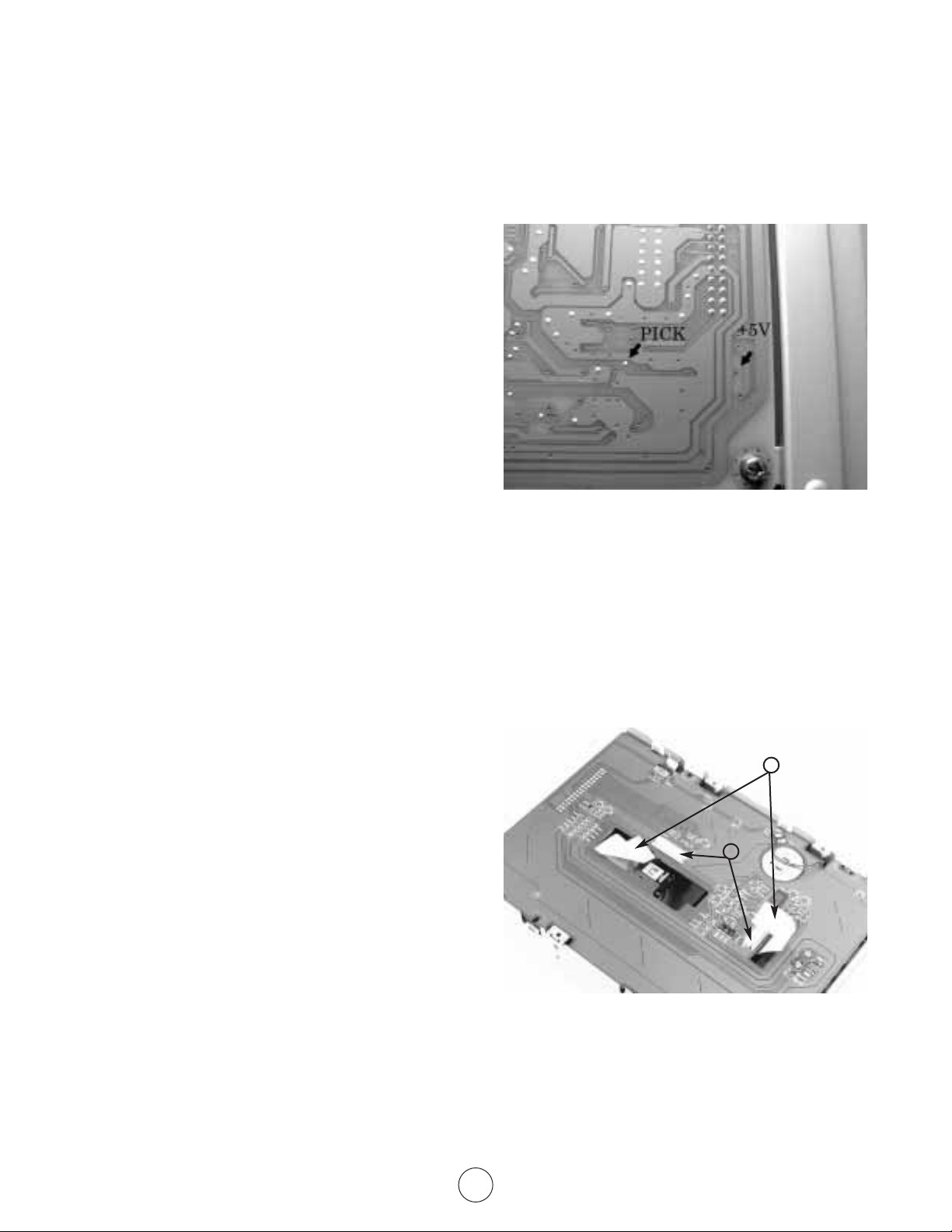
Measure the voltage across test points TP PICK
and TP +5 of the MAIN PCB to obtain the laser
diode current value in milliamps. When the
voltage exceeds 1.29 VDC (60 mA through
the parallel resistors R 201 and R 202), the
laser pickup must be replaced.
NOTE: This procedure only tests the laser diode.
There may be mechanical servo problems with
the laser pickup which can only be verified by
replacement of the laser pickup assembly.
Unlock two connector tabs (13) and disconnect
both flat flexible cables (FFC) (14).
CAUTION: Do not attempt to disconnect the
cables without unlocking the connector tabs or
damage may result.
laser diode test procedure
laser pickup replacement procedure
13
14

6
Turn the connect PCB (15) over while taking care
not to pull the DC motor wires (16).
Remove two glued screws (17) on the captive
guide shaft and one glued screw on the other
side of the laser pickup.
Remove the right shaft (18) and the two shaft
holders (19).
15
16
17
19
18
17

7
Remove the left shaft holder (19) in front of the
rack gear of the pickup.
Detach the pickup (20) from the shaft (18)
while holding the shaft.
Install the shaft (18) by putting it through
the new pickup (20).
19
20
18
20
18

8
Insert the FFC (21) with printed side up into the
pickup connector while taking care not to bend
the FFC.
Install the pickup (20) while inserting the
shaft (18) into the shaft holder (19) and
then attaching the other shaft holder.
NOTE: Apply one drop of light Sankol
mineral oil to each shaft if available.
Install the shaft (18) and shaft holder (19).
21
19
20
18
19
18

9
Tighten the three screws (17) to secure the pick-
up and make sure the pickup moves smoothly.
See above note regarding oil.
IMPORTANT NOTE: After replacement of the
laser pickup, it is necessary to remove the solder
bridge on the FFC. CAREFULLY remove the
solder bridge with a low wattage soldering iron
to break the short circuit.
Remove the three 2mm mounting screws (22).
Take note of the unused mounting hole (23).
spindle motor replacement procedure
17
17
22
23

10
Remove the FFC by loosening the connector
tabs. Detach the spindle motor (24) and the
plastic spacer (25). Lift the spacer with the
motor (the magnetic clamp will give some
resistance).
NOTE: Do not take tray from metal cover
or the magnetic clamp will fall out.
Insert FFC (26) into new spindle motor with
blue insulation toward the motor label.
Push connector tabs back to lock the cable.
Replace the three 2mm mounting screws (22).
NOTE: Do not place a screw in the unused
mounting hole (23) or balance problems
may result.
24
25
26
22
23

11
mechanism installation procedure after
replacement of pickup and spindle motor
Replace the connect PCB (15). Adjust the DC
motor wires (16) inside the wire slot. Take the
FFC’s (21, 26) out from each slot so that they
are not pinched under the PCB.
NOTE: If you have not already done so, carefully
remove the solder bridge on the laser pickup at
this time. See previous photo on page 9. If the
FFC’s are damaged, replace them with new ones.
Refit the mechanism bottom plate with
four screws (11).
Refit both metal side brackets (10) with two
screws each (9).
21
16
26
15
11
9
10

12
Insert the keyed ribbon cable (8) into the
mechanism connector (7).
Install the mechanism into the main chassis
with two screws (6).
Mount the bezel (5).
8
7
5
6

13
Eject the tray (2) with the eject stick (3).
Attach the tray mask (4) and manually
close the tray.
Mount the door (1).
2
1
3
4

14
main PCB replacement procedure
Remove the three screws (2) securing the top
cover (1).
Remove the top cover while lifting up toward
the rear panel as shown.
Disconnect the three cables (3) horizontally
connected (two on one side and one on the
other) to the main PCB (4).
2
1
3
4

15
Remove two screws (5) securing the main PCB
with the PCB guide (6).
Remove one screw (7) and one silver screw (8)
securing the main PCB to the rear panel (9).
Unplug the keyed connector (12) running to the
mechanism PCB while lifting the main PCB
upper front (11).
Reverse the above procedure to reassemble.
5
6
78
9
11
12

chassis assembly diagram
16

mechanism assembly diagram
17

18
block diagram
Other manuals for MCD-1000
1
Table of contents
Other Muzak CD Player manuals