MX Thermo Response QI Guide

Thermostatic Control
Instantaneous Electric Shower
Installation and User Instructions
IMPORTANT!
This Step-by-Step guide should be given to the customer
after installation and demonstration.
Thermo Response
QI

2
CONTENTS QI FEATURES
QI Features 2
Pack Contents 3
1. Shower Unit Familiarisation 4
2. Installation Check List 4
3. Important Safety Information 5
Installation
4. General Installation Layout Guide 7
5. Important Installation Information 8
6. Fixing the Shower to the Wall 8
7. Product Positioning Guide 9
8. Plumbing Connections 10
9. Electrical Connections 12
10. Changing the Operational Programmes 14
11. Fitting the Front Cover 15
12. Riser Rail Fitting Instructions 16
13. Commissioning the Shower 17
User Guide
14. Operating the Shower 19
15. How Your Shower Works 20
16. Routine Maintenance 21
17. Troubleshooting and FAQs 22
18. Troubleshooting Checklist for the Installer 24
19. Product Warranty 25
20. Service Policy 26
QI
QUICK INSTALLATION
a guide for installers
The MX range of Thermo Response QI shower
models have been specially designed for Quick
Installation. Both water and electrics can enter the
shower unit from 8 different positions. The unit is
wired internally to accept mains cable from both
the left and right hand sides of the back plate.
Removable corner sections allow for easy
plumbing connections. The screw mounting
hole positions are visible when the front cover
is removed. The top two fixing holes are vertical
key hole slots and the bottom fixing hole is a
horizontal slot to allow for alignment.
The inlet water filter is positioned so that it can
be removed quickly without taking the front cover
off for routine maintenance.
These instructions contain
all the necessary fitting and
operating instructions for
your electric shower. Care
taken during the installation
will provide a long, trouble
free life from your shower.
Thermo Response
Temperature
START/STOP
T
e
m
p
e
r
a
t
u
r
e
Flow
8 different entry points for maximum
installation flexibility

3
PACK CONTENTS
Please make sure ALL
components are included
before starting the
installation.
1. Shower Unit
2. Shower Handset
3. Riser Rail Tube
4. Riser Rail Brackets x2
5. Riser Rail Height Adjuster
6. Flexible Shower Hose
7. Soap Dish
8. Hose Retaining Ring
9. Screw Packs
10. Installation and User
Instructions plus
Guarantee Card
Thermo Response
Temperature
START/STOP
T
e
m
p
e
r
a
t
u
r
e
Flow
• 1.ShowerUnit
• 2.ShowerHandset
• 6.Flexible
Shower Hose
• 4.RiserRailBracket
• 3.RiserRailTube
• 5.RiserRail
Height Adjuster
• 7.SoapDish
• 8.HoseRetaining
Ring
• 9.ScrewPacks
• 10.FittingInstructions
& Guarantee Card
Instantaneous Electric Shower
Installation Instructions
IMPORTANT!
This Step-by-Step guide should be given to the customer
after installation and demonstration.
Thermo Response
QI

4
1. SHOWER UNIT FAMILIARISATION
Thermo Response
Temperature
START/STOP
T
e
m
p
e
r
a
t
u
r
e
Flow
2. INSTALLATION CHECK LIST
1. Check that the water supply will satisfy requirements .....................................
2. Check that water and cable entry points of the unit meet requirements ......
3. Check that the electric supply will satisfy requirements ..................................
4. Select a suitable position for the shower .............................................................
5. Plumbing installation ..............................................................................................
6. Electrical installation ...............................................................................................
7. Fit to the wall and connect the shower supplies ................................................
8. ONLY Commission the shower in the way described ......................................
9. Fitting the front cover and aligning the controls .................................................
10. Familiarise yourself with the user operating instructions ...............................
Tick off as you complete
Temperature buttons
Warmer (+) push button
Cooler (-) push button
“Secret ‘til Illuminated”
seven segment display
Flow Control knob
Start/Stop button
NOTE: the “Secret ‘til Illuminated” seven segment display shines
through the shower unit cover when the shower is operating to
indicate the water temperature or display error codes.

5
3. PLEASE READ THIS IMPORTANT SAFETY INFORMATION
Products manufactured by the MX Group are safe and without risk provided
they are installed, used and maintained in good working order in accordance
with our instructions and recommendations.
FOR THE USER:
WARNING: DO NOT operate shower if frozen, or suspected of being frozen.
It must thaw out before using.
DO NOT operate the unit if the showerhead or spray hose becomes
damaged.
DO NOT restrict flow out of shower by placing showerhead in direct contact
with your body or ther solid object.
WARNING: the outlet of the shower acts as a vent and must not be
connected to anything other than the flexible shower hose and handset
supplied or approved by the manufacturer.
DO NOT operate the shower if water ceases to flow during use or if water
has entered inside the unit because of an incorrectly fitted cover.
DO NOT place items such as soap, shampoo or other such bottles on top of
the unit as liquid could leak through the joint between the cover and back
plate and damage the sealing rubber.
The shower spray head and shower inlet filter MUST be cleaned regularly
to remove scale and debris. The frequency of the cleaning will vary
according to the local water quality. If the water outlet temperature
becomes hot and you are unable to obtain cooler water, immediately
check the shower handset and inlet filter for blockage. See section 16 for
cleaning instructions.
IMPORTANT: This appliance is not intended for use by persons (including
children) with reduced physical, sensory or mental capabilities, or lack of
experience and knowledge, unless they have been given supervision or
instruction concerning use of the appliance by a person responsible for
their safety. Children should be supervised to ensure they do not play with
the appliance.
!
!
!
!
!
!
!
!
!
!
!
!
!
!
!
!

6
FOR THE INSTALLER:
DEFAULT PLUMBING SETTING: The shower unit is supplied for right hand
mains water connection. To plumb the unit from the left of the shower back plate
you must remove the blanking cap by sliding off the metal retaining clip and refit
to the right hand side of the unit ensuring the metal retaining clip is refitted and
pushed firmly into the groove. Whilst leak testing the installation please ensure
that there are NO water leaks from this area.
IMPORTANT: To comply with water regulations, building regulations or any specific
local water company regulations and in accordance with BS EN 806 a double check
valve should be fitted where it is possible that the shower head may come into
contact with used water, for example in the bath or a shower tray.
IMPORTANT: Check that there are no hidden cables or pipes before drilling
holes for the wall plugs. Choose a flat piece of wall to avoid the possibility of
distorting the back plate and making the front cover a poor fit. Exercise great care
when using power tools near water. The use of a residual current device (RDC) is
recommended.
IMPORTANT: Before connecting the water supply to the shower
unit the water supply pipe should be flushed out to remove all debris. After
flushing the pipe work make the connection to shower inlet and ensure the
shower is positioned squarely on the wall and all fixing screws are tightened.
IT IS VERY IMPORTANT to ensure that the terminal block screws are FULLY
tightened and that no cable insulation is trapped under the screws. The earth
continuity conductor of the electrical installation must be effectively bonded to
earth on the fuse board.
IMPORTANT: Ensure that the flow control knob is turned to FULL flow and the
commissioning instructions are followed before switching the unit on. This will
make sure that the unit is full of water when first activated.
IMPORTANT: The shower unit MUST be full of water before the heat settings
are used.
PLEASE READ THIS IMPORTANT SAFETY INFORMATION (CONT.)

7
4. GENERAL INSTALLATION LAYOUT GUIDE
Plan your installation carefully. Check on the nearest
and most accessible rising main water supply, this
may be beneath the bath or in the loft, where it feeds
the water storage tank. Use only the cold rising
water main.
Avoid connecting the shower unit if possible where
it will be affected by water drawn off by another
appliance.
For example from the mains feed to the toilet as this
may cause a drop in pressure to a level that is too low
for the shower unit to work correctly.
A WRAS (Water Regulations Advice Scheme) listed
isolating valve must be fitted between the rising main
and the unit to comply with water regulations and to
allow for routine maintenance and servicing.
BATH
COLD WATER
MAINS SUPPLY
SEPARATE PERMANENTLY
CONNECTED SUPPLY
FROM CONSUMER UNIT
ISOLATING
STOP TAP
DOUBLE POLE
HEATER SWITCH
WALL MOUNTED
IN ACCORDANCE
WITH LOCAL
AUTHORITY
REGULATIONS
SHOWER
UNIT
BATHROOM
FLOOR
CEILING JOISTS
IMPORTANT
This appliance is not intended for use by persons (Including children) with reduced physical, sensory or
mental capabilities, or lack of experience and knowledge, unless they have been given supervision or
instruction concerning use of the appliance by a person responsible for their safety. Children should be
supervised to ensure that they do not play with the appliance.
!
!
!
!

8
5. IMPORTANT INSTALLATION INFORMATION
nShower installation must be carried out by a
suitably qualified person and be in accordance with
BS 7671 (IEE wiring regulations) building regulations,
water regulations and or any specific local water
company regulations in force and should be in
accordance with BS EN 806.
nThis shower unit is designed to be connected to a
15mm cold water mains supply.
nTo make sure the heating elements are activated
the shower must be connected to mains water supply
with a minimum running pressure of 100kPa (15lb/
sq in) – 1 Bar at a minimum flow rate of 8 litres per
minute. The maximum static pressure is 1000kPa
(150lb/sq in) 10 Bar.
NOTE: For 9.5kW units the minimum running
pressure must be obtained at 9 L/min.
For 10.5kW units the minimum running
pressure must be obtained at 11 L/min.
nThe shower unit must not be fitted where it may
be exposed to frost, for example in an outdoor area.
The shower must not be used if suspected of being
frozen. Frost damage is not covered by the guarantee.
nPlumbers jointing compound must not be used.
In instances of difficult joints use P.T.F.E. Tape.
The use of jointing compound will invalidate the
product guarantee.
nDO NOT solder fittings near the shower unit
as heat can travel along pipe work and damage
components.
nDO complete all plumbing connections before
making the electrical connections.
6. FIXING THE SHOWER TO THE WALL
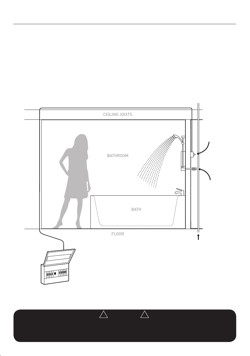
Position your shower on the wall so that it will NOT
be in the direct water spray from the shower handset
when fixed.
You may wish to consider mounting the unit so that
the shower handset could be used over a sink for
washing hair.
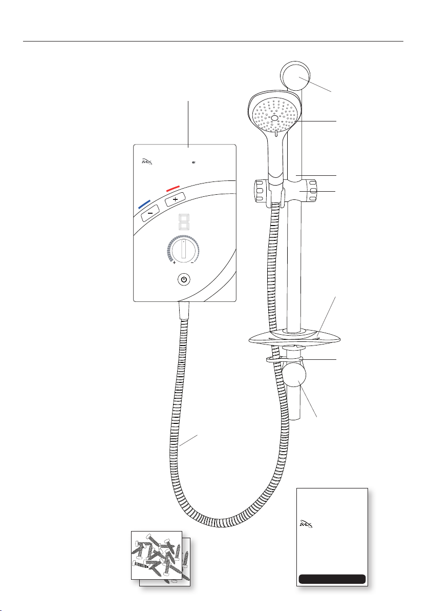
The shower unit should be positioned so that the
shower head cannot be immersed in the bath or
shower tray when hanging down. A shower hose
retainer is supplied with the accessories (see pages
3 and 9).
The unit can be mounted at a lower level if required
for less abled users and for use with a shower seat.
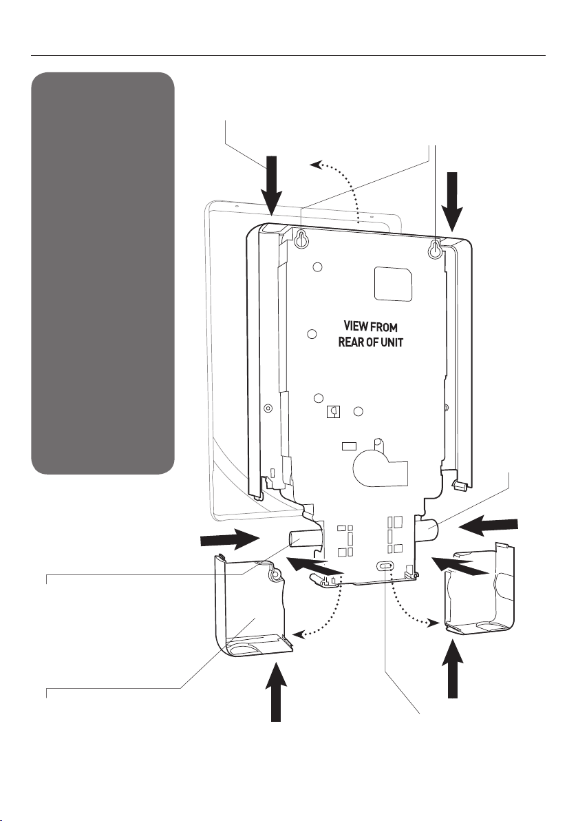
Remove the four front cover fixing screws and lift
the cover off complete with the warmer (+) and
cooler (-) push buttons and flow control knob in
place. Note the connector and lead attached to the
control PCB mounted on the shower back plate.
This will require connecting to inside of the front
cover before completing the installation.
Having decided on the water and cable entry points
and chosen a flat piece of wall hold the shower
vertically against the wall and mark the top two
fixing holes.
Carefully drill the two holes as marked using a sharp
5.5mm masonry drill after first making certain there
are no pipes or wires behind the proposed holes.
Insert the wall plugs and screws provided leaving the
screw head proud by approximately 5mm. The shower
can now be hung on these screws.
Make sure that the shower is positioned vertically now
mark and drill the lower slotted fixing hole. Then fix
the shower to the wall. Do not fully tighten the screws
at this stage.
The shower back plate has moulded knock out
sections which are clearly indicated to allow the
chosen service entry option to be removed prior to
final fix.

9
Thermo Response
Temperature
START/STOP
T
e
m
p
e
r
a
t
u
r
e
Flow
7. PRODUCT POSITIONING GUIDE
Shower unit can be mounted
either side of riser rail
Height of
showerhead
and shower
to suit user’s
requirements
Mains cold water supply
(either top, bottom, left,
right or rear entry
25mm minimum
Outline of bath or
shower tray
Spillover level
Spillover level
Soap dish
Hose retaining ring

10
8. PLUMBING CONNECTIONS
The 8arrows depict water
and electrical entry points
Location holes for
mounting are easily
marked off from inside
the unit
Bottom fixing position
Left hand
water entry
sealing cap
and clip
NOTE!
PLUMBING THE
SHOWER UNIT MUST
PRECEDE WIRING!
QI
QUICK INSTALLATION
As you can see from the
diagram right the shower
unit can be both plumbed
and wired from 8different
positions;
nTop right
nTop left
nBottom right
nBottom left
nRight side
nLeft side
nRear right
nRear left
Removable cover plates for left or
right and bottom inlets, accessible
once cover plate is removed.
Simply slide these into place
and secure with the fixing screw
before replacing the cover.
Water inlet, this can be switched
with the cap and fixing clip
opposite to change water
input direction.
See next page for instruction.

11
IMPORTANT
Before turning on the water supply to the shower unit the water supply pipe should be flushed out to remove
debris. After flushing the pipework ensure that the shower unit is positioned squarely on the wall and tighten
the screws. Tighten all plumbing connections and check the pipework for leaks.
IMPORTANT
To comply with water regulations, building regulations or any specific local water company regulations and
should be in accordance with BS EN 806. A double check valve must be fitted with all flexible
shower accessories where it is possible that the showerhead may come into contact with used water
i.e. In the bath or shower tray.
!
!
!
!
!
!
!
!
DEFAULT PLUMBING SETTING
The shower unit is supplied for right hand
installation. To plumb the unit on the left you must:
1. Remove the bottom left hand side cover plate.
2. Carefully pull the metal retaining clip out of the
blanking end cap with a pair of pliers.
3. Slide off the blanking cap.
4. Refit the blanking cap on to the inlet pipe on the
right hand side of the unit.
5. Re insert the metal fixing clip ensuring it is
pushed primly into place.
IMPORTANT: When leak testing the installation
you must ensure there are no leaks from this area.
PLUMBING CONNECTIONS (CONT.)
The shower back plate incorporates into the lower
right and left hand side of the back plate removable
trim sections to allow easy access when deciding on
and connecting to the water mains supply.
Remove the bottom right hand side cover plate giving
access to the inlet spigot.
IMPORTANT: Before connecting the mains water
supply to the shower, flush out the pipe work to
remove all swarf and system debris. This is achieved
by connecting a hose to the pipe work and turning on
the mains water supply at the isolating stop tap long
enough to clear the debris to waste.
Turn off the mains water supply at the isolating
stop tap.
Having decided on the direction of the water inlet
supply: Top (falling) Bottom (rising) or Rear Inlet, it
is necessary to remove the appropriate knock out
(thinned out plastic) cross section from the back
plate before commencing with the installation.
The connection to the unit is made using a 15 mm
copper, stainless or plastic pipe with a 15 mm
compression elbow or 15 mm push fit elbow.
IMPORTANT: Do not use excessive force when
making the connection to the unit.
Tighten the back plate fixing screws so the unit is
firmly fixed to the wall.
If rear entry pipe work is used we recommend the use
of a suitable sealant to seal around the incoming pipe
work to prevent water entering the wall.
Turn on the mains water supply and check for leaks.
At this stage no water can flow through the unit.
IMPORTANT: Remember to replace the lower inlet
covers before refitting the front cover

12
9. ELECTRICAL CONNECTIONS
The electrical installation must be in accordance with
the current BS 7671 (I.E.E. wiring regulations) and
part P of the building and / or local regulations.
The shower unit is designed for a single phase 50 Hz
a.c. electrical supply.
ELECTRICAL SPECIFICATIONS
IMPORTANT: The heating elements on the UK
models are manufactured to 240V specification and
will give a lower kW rating if the voltage supply is
below 240V.
The shower unit must be permanently connected
to the electrical supply, direct from the consumer
unit via a double pole linked switch with a minimum
contact gap of 3 mm. The switch must be readily
accessible and clearly identifiable and sited out of
reach of a person using the shower over a fixed
bath or shower tray, unless the switch is pull cord
operated. The wiring must be connected to the
switch without the use of a plug or socket outlet.
The supply cable size is determined by the kW rating
of the product (as detailed on the rating plate fixed
to the back plate) and the distance between the
shower and the consumer unit. The table below is
for guidance only but will help you choose the correct
cable for your installation. If you are in any doubt
consult an electrician.
The incoming cable should be hidden.
IMPORTANT: The shower unit is supplied with 2
separate sets of connecting terminal blocks mounted
on the shower back plate so that the shower can be
wired for left or right installations with minimum
effort. ONLY connect to one of the terminal blocks.
The diagram below shows the route of the cable into
the shower unit for connection to the terminal block.
(illustrated on left hand side)
IMPORTANT: Remove the appropriate lower cover
section to improve access for mains cable fitting.
Earth cable to terminal marked
Neutral cable to terminal marked N
Live cable to terminal marked L
IMPORTANT
Ensure that the terminal block screws are fully tightened and that no cable insulation is trapped under
screws. Ensure the cable clamp is used to secure the cable. The earth continuity conductor of the electrical
installation must be effectively connected to all exposed metal parts of other appliances and services in the
room in which the shower unit is installed to confirm
!
!
!
!
KW
RATING
NOMINAL
AT 240V
MINIMUM
RATING OF
ISOLATING
SWITCH
FUSE
RATING
MAX CABLE
RUN
6mm 10mm
7.5 31.25amps 40amps 40amps 29m 48m
8.0 33.33amps 40amps 40amps 27m 44m
8.5 35.41amps 40amps 40amps 23m 38m
9.5 39.58amps 40amps 40amps 21m 32m
10.5 43.75amps 45amps 45amps 18m 30m
N
E
Terminal
block
L
Nominal Power rating at 240V
8.5kW - (40A MCB rating)
9.5kW - (40A MCB rating)
10.5kW - (45A MCB rating)
Nominal Power rating at 230V
7.8kW - (40A MCB rating)
8.7kW - (40A MCB rating)
9.6kW - (45A MCB rating)

13
ELECTRICAL CONNECTIONS (CONT.)
The outer sheath of the supply cable must be striped
back to the minimum length as illustrated and the
earth conductor must have an earthing sleeve fitted.
Connect the cable to the terminal block. Ensure that
ALL the retaining screws are VERY tight and that NO
cable insulation is trapped under the screws. Loose
connections can result in cable overheating.
IMPORTANT: Failure to ensure that the retaining
screws are VERY tight could result in a failure of the
terminal block.
IMPORTANT: DO NOT switch on the electricity supply
until the shower cover has been fitted.
The diagram below shows a schematic wiring
diagram.
IMPORTANT: The use of connections within the unit
or other points in the shower circuit to supply power
to other equipment such as an extractor fan or pump
etc will invalidate the guarantee.
L
N
E
1
3
4
5
6
79
8
2
1. Heater body
2. Solenoid valve
3. Thermal cut-out
4. Power PCB
5. Triac PCB
6. Flow sensor
7. Inlet/outlet temperature sensor
8. Display/Control PCB
9. Start/Stop button PCB

14
10. CHANGING THE OPERATIONAL SHOWER PROGRAMMES
A four way DIP switch block is mounted on the main
power circuit board that allows the user to configure
certain shower functions. The settings can be
changed on installation by moving the control PCB
slider switches as described below.
The shower is supplied with:
•audiblefeedbackON(singlebleepsoundsonpush
button command)
•automatictimedSTOPfeaturesetatthemaximum
duration of 30 minutes.
NOTE: DIP switch is ON when slider switch in upper
position. DIP switch is OFF when slider switch is in
lower position.
Sound ON
slider switch 4 ON
Sound OFF
slider switch 4 OFF
Running Time 30 MINS
slider switch 1 OFF
slider switch 2 OFF
slider switch 3 OFF
Running Time 20 MINS
slider switch 1 ON
slider switch 2 OFF
slider switch 3 OFF
Running Time 10 MINS
slider switch 1 OFF
slider switch 2 ON
slider switch 3 OFF
Running Time 5 MINS
slider switch 1 OFF
slider switch 2 OFF
slider switch 3 ON
ON DIP
1 2 3 4
SOUND
SWITCH
RUNNING
TIME
DEFAULT SETTINGS
Sound: ON
Running time: 30 MINS
ON DIP
1 2 3 4
ON DIP
1 2 3 4
ON DIP
1 2 3 4
ON DIP
1 2 3 4
ON DIP
1 2 3 4
ON DIP
1 2 3 4
ON DIP
1 2 3 4
ON DIP
1 2 3 4
ON DIP
1 2 3 4
ON DIP
1 2 3 4
ON DIP
1 2 3 4
ON DIP
1 2 3 4

15
11. FITTING THE FRONT COVER
IMPORTANT: it is necessary to align the flow control
knob on the cover with its opposite control spindle
before the cover is fitted. In addition connect the flying
lead from the PCB to the rear of the front cover.
First turn the flow control knob anti-clockwise to the
mechanical stop position (maximum flow).
Then rotate the flow control spindle on the back plate
fully anti-clockwise to the mechanical stop position
(maximum flow).
Hold the front cover carefully and attach the flying
lead from the control PCB (ensuring that the lock
tags are aligned with the slots on the display PCB
connector) to the rear of the front cover as illustrated
making sure that the connector pins are fully engaged.
The cover can now be fitted. Please ensure that the
flow control knob engages with the spindle correctly
and the connector ribbon is not trapped between the
covers. The front cover can now be secured with the
four fixing screws provided.
Following the installation of the riser rail (see section
12), attach the flexible hose to the shower outlet
positioned centrally on the back plate making sure
that you use the seal washer provided. The shower is
now ready for commissioning.
STOP
STOP
Temperature
Flow
START/STOP
T
e
m
p
e
r
a
t
u
r
e
Thermo Response
QI
Temperature
Flow
START/STOP
T
e
m
p
e
r
a
t
u
r
e
Thermo Response
QI

16
12. RISER RAIL FITTING INSTRUCTIONS
1. Establish the height of the riser rail to suit
requirements, taking into account all users.
2. Remove caps and covers from brackets.
3. Mark the position of the lower bracket then drill and
plug the wall. If this is a replacement installation
locate the bottom hole.
4. Fit rail through lower bracket and clamp. Place the
remaining bracket on top of the rail making sure
the slot in the rail is located in the notch.
a. For a replacement riser fix the top bracket using
the existing hole.
b. For a new installation ensure the hole position
is vertically aligned and mark the wall. Unclamp
the lower bracket and remove the rail then drill
and plug the wall before fixing the top bracket
into position.
5. Slide the height adjuster onto the rail. Tighten to
the rail by turning the locking cap. Then fit the
soap dish – dampening the rail will make it easier
to slide on. Finally fit the hose retaining ring onto
the bottom of the rail below the soap dish.
6. Replace the rail assembly through the lower
bracket. Fit the rail into top bracket ensuring
the slot locates into the notch. Tighten the lower
bracket then refit the bracket caps.
NOTE: The adjustable height adjuster grips the conical
ends of the hose, not the handle of the showerhead.
CAUTION
Check there are no hidden cables or pipes before drilling holes for wall plugs.
Exercise great care when using power tools near water.
The use of a residual current device (RCD) is recommended.
!
!
!
!
TIPS
A piece of insulating or masking tape applied to
the wall before marking out the fixing holes will
help stop the drill from wandering, particularly on
tiled surfaces. When working near a basin or bath,
insert the plug in the waste fitting so that small
parts cannot be lost.
Take care not to drop accessories or tools into
basin or bath.
!
!

17
13. COMMISSIONING THE SHOWER
IMPORTANT: The MX Thermo Response thermostatic
control shower unit incorporates a commissioning
procedure detailed below. It is important that this
procedure is followed.
1. Make sure that the electricity supply has been
isolated at the double pole isolating switch.
2. Turn the Flow control fully anti-clockwise to the
maximum flow position.
3. Ensure that the water supply is fully on at the mains
stop cock and isolating service valve (if fitted)
4. Check that water is not leaking from the bottom of
the case.
5. Switch on the electrical supply at the double pole
switch or pull cord. The power on neon indicator
will light at the switch.
6. On the shower unit press and hold the plus and
minus temperature buttons for a minimum of 3
seconds. The unit will bleep once and COLD water
flows into the shower and through to the shower
handset. When the water is free flowing and all
the air has purged through the system press the
start /stop button and this will stop the water flow.
7. Set the Flow control to mid position.
8. Press the start /stop button, you will hear an
audible bleep and the water will flow freely within a
few seconds.
NOTE: If the commissioning procedure is not used
the heaters will have a 6 second delay before they are
energised to allow the water to fill the unit (this only
happens on the first start up operation).
IMPORTANT: If the button does not respond ensure
that the flying lead from the PCB has been connected
to the back of the front cover. Ensure front cover is
isolated at the mains supply before removing.
9. The “Secret ‘til Illuminated” seven segment
display will activate and display digit 0.
10. Press the warmer (+) button and the display will
change to show digit 1. This will be confirmed
by a single audible bleep (if not deselected on
installation). Keep pressing the warmer (+)
button repeatedly until the digit reaches 6 which
when stable will give an outlet temperature of
approximately 40°C. This could take up to 30
seconds if the shower is starting from cold.
11. Fine tune the flow control to give a good shower if
required.
IMPORTANT: If the flow control valve is set to a very
high flow and the unit cannot reach the temperature
selected the seven segment display will continue to
blink once every 3 seconds. This indicates that the
flow rate needs to be reduced until the digit stops
blinking and the shower has reached the requested
temperature. Alternatively a lower temperature could
be selected.
12. Press the start /stop button to switch the unit off.
A single bleep will sound and initiate the PHASED
SHUT DOWN operation, detailed next.
IMPORTANT
The shower unit must be full of water before heat settings are used.
IMPORTANT
Turn the Temperature control knob anti-clockwise until the valve is fully open before switching on the unit.
This will ensure a fast fill up of the unit when the shower is first switched on.
!
!
!
!
!
!
!
!

18
COMMISSIONING THE SHOWER (CONT.)
PHASED SHUT DOWN
The Phased Shut Down operation is activated when
the shower is stopped using the start /stop button.
It switches the heating elements OFF but allows the
water to run for approximately 6 seconds taking the
residual heat away from the elements and giving a
cool start up for the next user.
1. The seven segment display shows this operation by
counting down the horizontal bars 3 - 2 – 1 OFF
2. Switch off pull cord or wall mounted switch
IMPORTANT: When the shower is re-started it will
reach the temperature set by the last user as this has
been stored in the unit’s memory.
3. Finally we recommend that the shower head is
removed to make sure no debris has worked into it
and the inlet water filter is checked and cleaned of
any debris from the incoming pipe work. Clean and
re fit (see section 16 for cleaning instructions).
4. Make sure that the water supply is fully turned ON.
CAUTION
Always use the start /stop button to switch the shower OFF. If the pull cord or surface mounted isolator
is used to stop the shower without first pressing the start /stop button then you will by-pass the phased
shut down mechanism
!
!
!
!

19
14. OPERATING THE SHOWER
1. Switch on the electrical supply at the pull cord
or wall mounted switch. The power on neon will
illuminate indicating the switch is on.
2. Press the start /stop button for immediate water
flow. This is confirmed with a single audible bleep.
We recommend that you do not stand under the
spray from the shower handset when switching on.
3. Wait until the water has reached a stable warm
temperature.
4. The “Secret ‘til Illuminated” seven segment
display will activate and show through the front
cover displaying the last temperature selected
from the previous shower (the in built memory
is programmed to remember the last setting).
5. The shower outlet temperature will increase until
it reaches this pre determined temperature.
This could take up to 30 seconds if the shower is
starting from Cold.
NOTE: The seven segment numerical display
indicates the shower outlet temperature where 0 is
cold, digit 1 represents a nominal 30°C and digit 9
represents a nominal 47°C.
NOTE: The average showering temperature is 40°C.
This corresponds to digit 6 on the numerical display.
The outlet water temperature will stabilise and the
unit will control the temperature thermostatically
during the shower.
TO INCREASE THE TEMPERATURE
1. Press the warmer (+) button ONCE. The digit will
move, for example from 6 to 7 confirmed by a single
audible bleep. The water temperature will increase
by a nominal 2°C. Wait approximately 30 seconds
for the shower to increase the temperature to the
new setting.
2. Repeat this if necessary to achieve your ideal
temperature setting waiting each time for the
new temperature to be achieved.
IMPORTANT: For safety the maximum outlet
temperature of this shower is limited by the
thermostatic control to a nominal 47°C.
TO DECREASE THE TEMPERATURE
1. Press the cooler (-) button ONCE. The digit will
move, for example from 6 to 5 confirmed by a single
audible bleep. The water temperature will decrease
by a nominal 2°C. Wait approximately 30 seconds
for the shower to reduce the temperature to the
new setting.
2. Repeat this if necessary to achieve your ideal
temperature setting waiting each time for the
new temperature to be achieved.
FLOW CONTROL ADJUSTMENT
The flow control allows the water flow through the
shower to be reduced or increased. Once the flow
control has been set only occasional fine tuning will
be required
IMPORTANT: If a very high flow is set and the unit
cannot reach the temperature selected the seven
segment display will continue to blink at the rate of
once every 3 seconds. You will need to reduce the
flow rate in stages until the digit stops blinking and
the shower has reached the requested temperature
remembering to wait between each selection for the
shower to respond. Alternatively a lower temperature
could be selected via the cooler (-) push button.
IMPORTANT: Always use the start /stop button to
switch the shower OFF. If the pull cord or surface
mounted isolator is used to stop the shower without
first pressing the start /stop button then you will by-
pass the phased shut down mechanism.
Finally switch OFF at the pull cord or wall mounted
isolating switch.

20
15. HOW YOUR SHOWER WORKS
1. The cold incoming water is heated instantaneously
as it flows over the heaters in the heat exchanger
assembly.
2. At the start up the control will reach the outlet
temperature selected at the last use and stored in
the unit’s memory. This could take up to 30 seconds
if started from cold.
3. The seven segment display will illuminate and
indicate the set temperature. This will normally
correspond to digit 6 which indicates a nominal
outlet water temperature of 40°C.
4. When pressing the warmer (+) or cooler (-) push
buttons the water temperature set point is adjusted
automatically by the electronic control by a nominal
2°C and the seven segment display will move one
digit higher or lower.
5. Please note when making adjustments in
temperature the display will change immediately
by one digit and will continue to blink until the outlet
temperature has reached the new target. This could
take up to 30 seconds.
6. The amount of hot water available at the set
temperature is limited by the total power of the
heater.
7. Audible feedback to all push button command is
included. (unless deselected at installation)
8. The Water is turned on and off by the solenoid valve
built into the shower.
9. The water flow and inlet / outlet water
temperatures are monitored to provide information
to the control PCB at all times the shower
is operating.
10. A stabiliser built into the water flow valve
automatically compensates for small fluctuations
in water pressure that frequently occur in
households. There are three further controls that
cater for exceptional restrictions in water pressure
to prevent the shower from getting too hot.
a. If the water flow is less than 2L/min the power
to the elements is switched off but the solenoid
remains on allowing water to flow through the
unit. This is indicated by the display showing
the letters “L–P” (low pressure).
b. If the outlet water temperature reaches 55°C
then the heater elements and water solenoid
are switch off giving full shut down for ultimate
user protection. This is indicated by the display
showing the letters “o –t” (over temperature).
See page 22 for further details.
c. A two stage mechanical cut-out is mounted on
top of the heat exchanger independent of the
electronic controls. Stage 1 switches the power
off to the elements if it senses an excessive
temperature. The switch operates with an
audible click and will re set if cold water is run
through the shower. The shower display will
temporarily indicate the letters “o –t” (over
temperature) Stage two only operates if an
extreme temperature is sensed. The cut-out
will permanently switch off and will then have
to be replaced.
11. A pressure relief device is fitted to safeguard
against a build up of pressure in the heater. It
provides protection to the heater should there be
an excessive build up of pressure. If this device
operates then a replacement part will be required.
Table of contents
Other MX Plumbing Product manuals
Popular Plumbing Product manuals by other brands

Excellent
Excellent MAZO KAEX.3023 installation instructions

American Standard
American Standard One 2064.461 installation instructions

Grundfos
Grundfos Sololift2 D-2 Installation and operating instructions

BETTE
BETTE BETTEAQUA installation manual

Inta
Inta VR994CP quick start guide

HOLL'S
HOLL'S Hybrid Combi HL-HC04-RS Installation handbook

VIGO
VIGO Edison VG15464 manual

Hans Grohe
Hans Grohe Shower Select 15765000 Instructions for use/assembly instructions

Joycare
Joycare JC-350 instruction manual

Riobel
Riobel PB66C-EM installation guide

PolyJohn
PolyJohn HandStand 2 user manual

Hans Grohe
Hans Grohe Talis S 32841010 Instructions for use/assembly instructions