MyFlyDream MFD AAT User manual

MyFlyDream
Automatic Antenna Tracker
Manual
V 3.0
www.MyFlyDream.com

Notes
Thank you for purchasing the MyFlyDream Automatic Antenna Tracker (hereinafter
referred to as MFD AAT).
Please follow this manual to get familiar with the tracker and to operate it correctly.
The tracker is a precision mechanical and electronic device. Please read this
manual carefully to avoid damaging the device or hurting yourself and others.
The tracker is designed for use with RC-models only. Please use it in compliance
with applicable local laws. The reliability and accuracy of the tracking system
depend on a number of factors. A strong electromagnetic interference, bad GPS
status and other reasons may cause a bad tracking result. Please consider the risk
and take it yourself. Any loss or damage caused by the tracker system is not our
responsibility.
We reserve the right to continuously improve the product performance, so this
document is not necessarily in full compliance with the tracker you purchased. The
latest version of this document will be available at our website:
www.MyFlyDream.com
1.System Components
1. MyFlyDream Tracker
2. MyFlyDream TeleFlyOSD
3. MyFlyDream AATDriver
4. Cables connecting the AAT and your AV receiver
5. 7Pin Connector (for 12 channels version only)

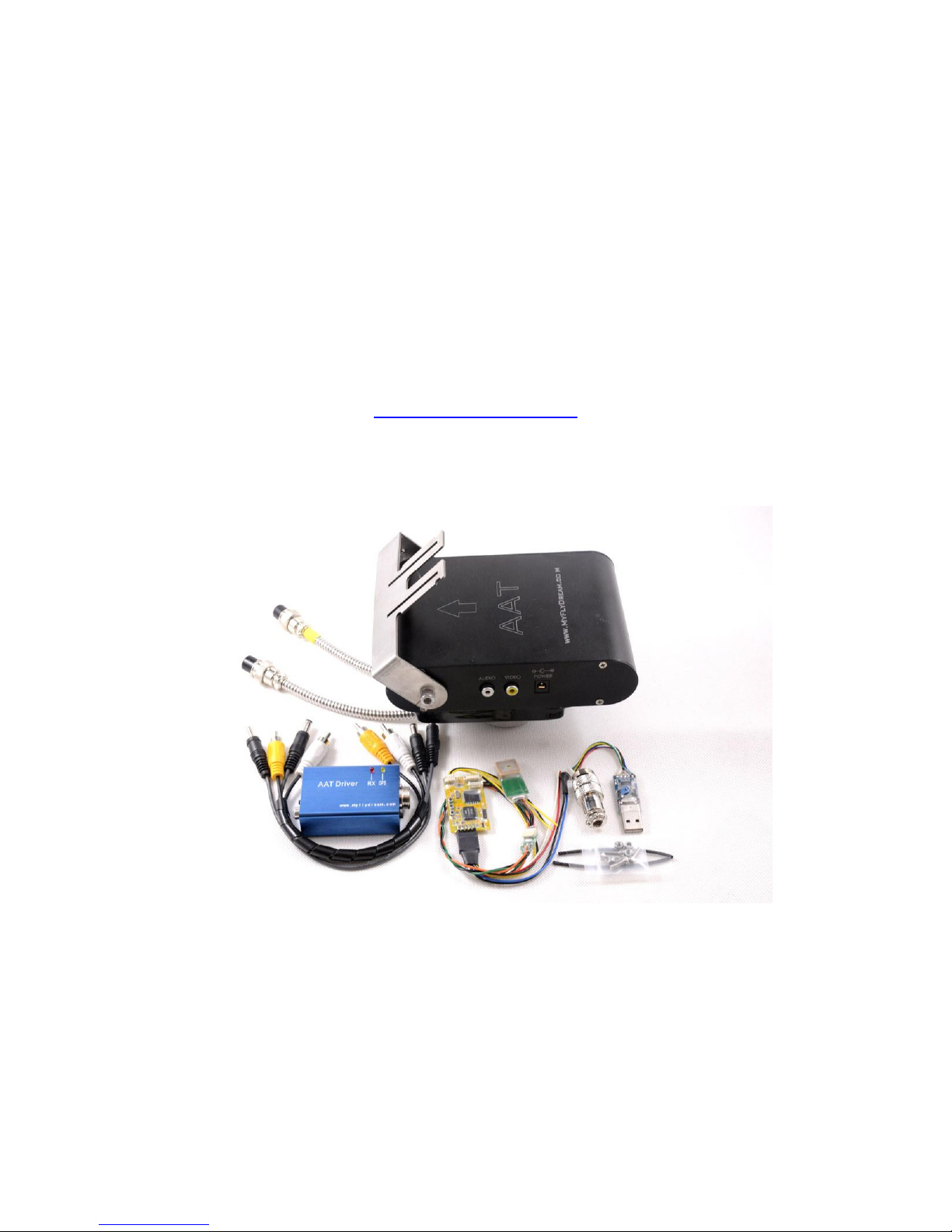
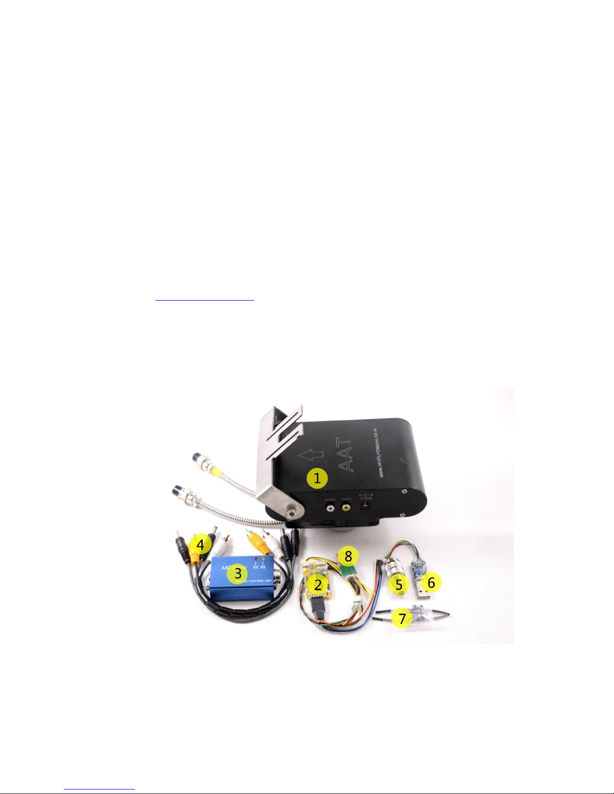
6. USB Programmer (for firmware update)
7. Heat shrinkable tubes and M3x8mm stainless steel screws/nuts
8. Connector between the AAT and your AV receiver
2.Working Principle
In FPV flight, in order to get a better quality of video signal reception, we often wish to
use high-gain antenna. But any high-gain antenna is accompanied by a narrow effective angle.
MFD AAT is designed to solve the difficulty to keep the directional antenna pointed at the
target to ensure the best possible reception and transmission during FPV flight.
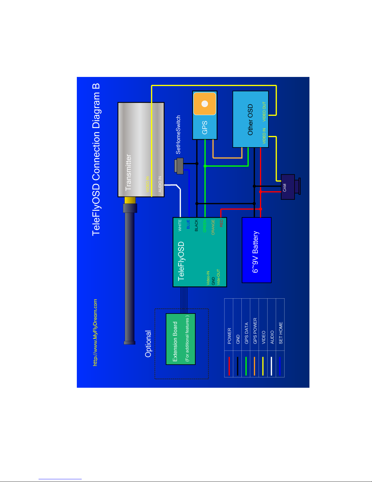
To form a complete system, you need to mount the TeleFlyOSD module on the plane. The
TeleFlyOSD reads data from the GPS on the plane, encodes and modulates the planes
coordinates and height information and transmits them back via a wireless audio channel
(usually the audio channel of the video transmission link is used).
The tracker forwards the audio signal received to the AATDriver. The AATDriver
demodulates and decodes the signal to obtain the plane position information. After
comparing with the original coordinates, it gets the current plane azimuth, distance and
height, etc. relative to the tracker. Then the AATDriver transmits the information to the
tracker that drives the internal servo to aim the directional antenna at the planes position.
3. Specifications
With a built-in high quality electrical slip ring, MFD AAT has a unrestrained, continuous
panning capability. There is also a built-in electronic compass which makes it as a
Plug-and-Play system without extra initialization.
Tracker:
Weight
905g
Size
165*107*40mm (Length*Wide*Height)
Input voltage
12V
Current consume(empty load)
100mA
Loading capacity
1KG
Tilt range
0~90 Degrees
Pan range
Unlimited (0~∞ Degrees)
Tilt speed
100 Degrees/s
Pan speed
200 Degrees/s
Spare signal channels
1~7

TeleFlyOSD:
Weight
(Not including the harness)
9g
Size
45 * 25 mm
Input voltage
7~20V (7~13V if connected with an
ExtensionBoard)
Current consume
100mA
AATDriver:
Weight
58g
Size
78*44*23mm (Length*Wide*Height)
Input voltage
12V
Current consume
100mA
Virtual GPS
Communication
baud rate
1200bps
*Virtual GPS:AATDriver can virtualize itself as a bluetooth
GPS module. It outputs the location information of the
plane with $GPGGA and $GPRMC command.
4. Connection and Set-up
1) Connecting TeleFlyOSD
Introduction to TeleFlyOSD

Part #
Name
1
Extension board port
2
OSD video signal port
3
UP button
4
SET button
5
DOWN button
6
Connecting pins
7
LED
8
Firmware upgrade socket
Wires color and function
Colour
Name
Remard
Red
Power
Power input
Black(3 wires)
GND
Ground
Blue
SetHome
Set the tracker position
Green
GPS Data
GPS Data
Orange
GPS Power
GPS Power supply(3.3V) *
White
Audio Out
Audio output to transmitter
Yellow
Video Out
OSD video output to transmitter
* Maximum current output: <200ma. Please make sure that your GPS current consumption
does not exceed these limits.
Connecting TeleFlyOSD
The TeleFlyOSD can either use a separate GPS or share a GPS with another
component (OSD, Autopilot).
Please refer to Connection Diagram A if a separate GPS is being used. In this

configuration, the TeleFlyOSD powers the GPS.
In the diagram, the operating voltage of GPS is assumed to be 3.3V. If your GPS needs
an operating voltage of 5V, refer to Appendix A.
Please refer to Connection Diagram B if a GPS is shared with another component
(OSD, Autopilot). In this example, the GPS and another OSD connect as usual for
power supply.
See Chapter 7 “OSD Functions” for specific OSD functions of TeleFlyOSD.

Connection Diagram A (power the GPS by TeleFlyOSD)

Connection Diagram B (share GPS with other OSD)

Selecting appropriate baudrate for TeleFlyOSD
Since the output data rate of different GPS may be different, it is necessary to set the
baudrate of the TeleFlyOSD communication port to match the GPS used. There is a
two-way DIP switch on the backside of the TeleFlyOSD module which is used to select
baudrates:
The arrow-indicated DIP switch in the figure has an ON mark above. There may be four
different baudrate combinations via setting of this switch:
DIP Status(1-2)
Communication Bardrate(bps)
OFF-OFF
115200
OFF-ON
38400 (Default)
ON-OFF
57600
ON-ON
9600
Power on after checking correct connection. The TeleFlyOSD LED will turn on. After
a few seconds, if the communication between TeleFlyOSD and GPS is working normally,
the LED will flash at half the GPS data update frequency. If the LED is lit continually,
check whether the GPS connection and baudrate setting are correct.

2). Mounting tracker and AATDriver
Please mount the antenna on the antenna handler of the tracker firmly. The image
transmission receiver is suggested to be mounted on the antenna handler to avoid
electronmagnetic interference. Antenna cables tend to be stiff, continual bending due to the
movement of the tracker might damage it. Specific mounting methods should be designed
according to the actual situation. The following picture is for reference only.
Connect the AATDriver to the tracker and mount the tracker on the tripod. Do not ever
try to hold the tracker in hand to test it to avoid damage to the device and yourself. Three
cables lead from the tracker: black 5.5mm power plug, yellow video plug and white audio
plug. Connect the three cables to the corresponding jacks on your video transmission
receiver. Please note that the 5.5mm power plug is directly connected to the power supply of
the AATDriver. For example, if the power supply voltage for the AATDriver is 12V, the power
plug output is 12V, too. If the interface specifications or power supply voltage do not match
your image transmission receiver, you need some additional hardware like a step-up or
step-down regulator to connect them.
Finally, connect your monitor to the yellow RCA terminal of the AATDriver to view the
video signal.

3).Preliminary system test
Power on the AATDriver with 12V DC. The red LED and yellow LED on the
AATDriver will flash for several times and then go out. Flashing 5 times means the
data output of the AATDriver is currently in MFD mode and flashing 2 times means
it is in VGPS mode. The meaning of the two modes will be explained in the following
chapter “Advanced Use”.
The tracker plays a “Beep” sound after power-on. The antenna handler turns to an
elevation of 30 degrees, and the red LED (offline indicator) on the tracker flashes
continually. That means the tracker is ready. The power indicator of the image
transmission receiver on the tracker should also turn on.
Press the TEST button on the AATDriver. The red LED on the AATDriver will turn on
to indicate it is in TEST mode. If the tracker works normally, you will see the tracker
turn as per the following parameters by pressing the TEST button in turn:
TEST sequence #
Azimuth
Tilt
1
0 (North)
0
2
90 (East)
30
3
180 (South)
0
4
270 (West)
60
5
(Quit test mode)
(Quit test mode)
It is recommended to conduct the above system test once before flight to ensure the
tracker and driver hardware and software work properly. But remember to exit test
mode before taking off, or the tracker will not start to track.
Power on the TeleFlyOSD and image transmission transmitter. The red LED on the
TeleFlyOSD should start to flash after turning on for a few seconds. If the video
transmitter/receiver channels match with each other and the data link is good, the
red RX LED on the AATDriver will flash continually. Every time a valid packet is
received, the Red LED flashes.
Press and hold the SetHome button on the TeleFlyOSD. If the communication is good,
the tracker will play a “Beep...” continuous sound for as long as you hold the button,
indicating that the “Home” position coordinates have been successfully set. On
releasing the button, if the GPS does not lock more than three satellites at the
moment, the tracker will play a rapid “Beep...Beep...Beep...” warning sound. If that
happens, give the gps some time to acquire more satellites and try again.
If the above test steps are passed through normally, it indicates the system
connection and configuration are correct and you can start conducting flight tests
outside.

5. How to use the AAT
Power on all equipments and use the test button on the AAT Driver to check the
tracker. Check to ensure the four pointing directions are basically correct and the
red RX LED on the AATDriver flashes continually.
It takes time for the GPS to search satellites. Wait for a while and check the GPS
status according to the flashing frequency of the yellow LED on the AAT Driver. The
higher the frequency, the better the GPS status. In the best condition, the yellow LED
will stay lit. Check to ensure a good GPS positioning status before the next step.
Place the plane as close as possible to the tracker and press the SetHome button on
the TeleFlyOSD module for about three seconds. The tracker will play a “Beep...”
sound, indicating the current position has been set as “Home”.At the same time, the
red LED on the tracker starts to flash, and the antenna should pitch up to a 30
degree angle. That means the tracker is in Stand-By for tracking.
You can manually spin the tracker towards the take-off direction while it is in the
standby mode to ensure the best angle of signal reception in the take-off phase,
because the tracker won’t start tracking unless the plane is 10 meters away.
Take off your plane now. Once the plane leaves the tracker 10 meters away, the red
LED on the tracker turns off and the tracker immediately starts tracking (the tracker
will not stop tracking even if the plane flies back to within 10 meters).
Notes:
Before take-off make sure the AATDriver is not in test mode (the red RX LED on
the AATDriver will stay lit in Test mode) and that the tracker is not in Offline
mode (the red Off-Line LED on the tracker will stay lit in Offline mode). In both
of these special conditions, the tracker will not track the target.
If the downlink is broken or the GPS is in a very bad status after SetHome, the
tracker will play the “Beep...Beep...” sound and the red LED blinks, warning you
that the tracking capability has been lost. In this situation, you can spin the
tracker by hand towards the proper direction if necessary (pitch angle will
maintain the angle before loss of signal). The system will automatically resume
tracking as soon as there is a valid signal again.

6. Advanced Usage
Setup and operation of the tracker
There are 3 LED indicators and buttons on the right side of the tracker. From left to right,
the buttons (LEDs) are:
Off-Line (Red)
North (Yellow)
Cal. (Green)
Common functions and operations of the tracker:
Function
How to operate
Remark
Enter/Quit offline
mode
Press the
Off-Line
button
In offline mode the tracker
stops tracking. You can
manually turn the tracker in the
direction you need.
You can press the "Off-Line" button
to enter the offline mode. The
red light will be on to indicate the
tracker is in offline mode. Press
the "Off-Line" button again to quit the
offline mode.
Hard iron
calibration
1.Enter offline mode
2.Then press the
Cal. button,
3.Quit offline mode.
Enter Offline Mode, Press
the "Cal." Button once, the green LED
will light after 2 seconds. The tracker
starts to rotate automatically to
calibrate itself.
Please wait until the green light is
off, which means the calibration is
done.
The tracker will stay in a random
direction after calibration.
Reset to factory
default
1.Enter offline mode,
2.Press the Cal. Button
3. Then press
the North button immediately
within 2 seconds
The green light of the tracker will
flash 5 times at the same time, which
indicates that the tracker resets to
the factory default settings and all
the calibration data is cleared.
CAUTION: If you don’t press North
button within 2 seconds after
pressing CAL. button,
the tracker will start to execute the
hard iron calibration.

Description of the tracker LED indicators:
Indicator
Status
Meaning
Off-Line
(Red Light)
Off
The tracker is tracking.
On
The tracker is in off-line mode.
Flashing
The tracker stands by. If you have set home
position, the tracker will start to track once
the target moves 10 meters away.
North
(Yellow Light)
Flashing
The tracker is executing the North calibration.
CAL.
(Green Light)
On
The tracker is executing the hard
iron calibration.
How to use the auxiliary channels of the tracker
There is 1 auxiliary channel available in a 6-channel tracker and 7 auxiliary channels are
available in the 12-channel version. Users can use these auxiliary channels to transmit their
own signals. For example, you put a data radio on the tracker, so maybe you need to connect
the TX, RX, Power and GND from the data radio to your ground device. Use the auxiliary
channels so that you can transmit the data without obstructing the tracker to rotate
continuously.
To use these auxiliary channels you need to remove the left side panel. These pictures
show how to remove the panel step by step:

After removing the left panel you will see there are 7 soldering pad on the PCB. They are
numbered from 1 to 7.
A 6 channels tracker has only a 6 pin plug. The Aux Channel 1 maps to PIN#3 of the
plug.
A 12 channels tracker has two plugs, one 6Pin, one 7Pin. The 6Pin plug is used to
connect to AATDriver. PIN#3 of the 6 pin plug is a null pin. The Aux Channel 1 to 7 map to
PIN#1 to PIN#7 of the 7pin plug.
CAUTION: The maximum current allowed for each channel is 2A. Don’t exceed this limit
or the slip ring will be damaged.
Setup and operation of the AATDriver
Common functions and operations of the AATDriver:
Function
How to operate
Remark
Toggle between MFD
mode and VGPS mode
Hold down
the HOME button to
power on
After powering on, the yellow LED or the
red LED of AATDriver will flash rapidly.
The flashing of the yellow LED indicates that
the current mode is VGPS mode, the flashing
red one indicates the MFD mode.
Power off and then power on again,
AATDriver will start working in the new
mode.
Every time you power on while pressing the
HOME button, AATDriver will toggle
between the two modes
Every time you power on without pressing

the HOME button, the yellow and the red
lights of AATDriver will blink several times.
2 times means the tracker is currently
in VGPS mode, 5 times in MFD mode.
Set the origin
coordinate for
tracking
Press the Home
button
The current location of the aircraft will be
recorded as the home coordinates. The
tracker needs a Home position set to track.
Description of the AATDriver LED indicators:
Data mode
LED Behaviour
Remark
RX
(Red Light)
Off
No data received.
On
It is currently in test mode.
Flashing
Downlink data is received successfully .
GPS
(Yellow Light)
Off
GPS lock has not been obtained.
On
GPS is in a perfect status. (10 or more
satellites are locked)
Flashing
Indicating GPS status. The faster the LED is
flashing, the more satellites are locked.
The relationship between the frequency and
the number of locked satellites is as follows:
0.5HZ: 1 ~ 3 satellites
1HZ: 4 ~ 5 satellites
2HZ: 6 ~ 7 satellites
5HZ: 8 ~ 9 satellites
AAT Calibration procedure
If you are not satisfied with the tracking precision, please calibrate the tracker follow
the next steps.
Step
How to operate
1. Reset to factory
default
◆Power on the tracker.
◆Press Off-line button to enter off-line mode.
◆Press Cal. button, then press North button within 2 seconds.
The tracker is reset to default now.
◆Press Off-line button to quit off-line mode.
2. Calibrating the
middle point of
the PAN servo
◆Press the “TEST” button on the AATDriver, The tracker will now
point to NORTH. (red led on AAT driver goes to solid red).
◆Now press the “HOME” button on the AATDriver once, the
tracker will “Beep”. Press the “HOME” button again and again, the
tracker will rotate faster and faster or slower and slower.
◆When the rotating stops, STOP pressing the “HOME” button.
You have found the “Middle-point” of the pan servo.
◆When you found the “Middle-point” position then press the
“TEST” button for 4 times until the “RED LED” on AATDriver goes

off. Pan servo calibration result is saved
NOTE:
If you press the “HOME” button too fast, you may accidently miss the
“middle-point”. Just press the “HOME” button again and again, this
procedure will loop again.
3. Hard Iron
Calibration
◆Press Off-line button to enter off-line mode.
◆Press Cal. button and wait.
◆The tracker will start to rotate for a while.
◆When the tracker stops rotating, press off-line button to quit
off-line mode. The calibration result is saved.
*TRIM Mode
Usually we don’t suggest to use this feature, but you can try it if you are still not satisfied
with the tracking performance. This feature is used to trim the tracker to left or right if the
tracker is not facing the plane correctly.
Procedure:
1. Hold the “CAL.” Button on the Tracker while powering on, after powering on release the
“CAL.” Button. You have now enabled TRIM mode.
2. During flight press “North” Or “CAL.”button to trim left or right until tracker is facing the
plane correctly.
Trimming is also possible in TEST mode. You can use TEST button to made the tracker face to
north, then user “NORTH”or “CAL.”button to trim it until it points to north exactly.
3. Enter Off-line mode then quit off-line mode to save the trim result.
Connect AATDriver to external devices
The AATDriver has a built-in Bluetooth module. Using Bluetooth you can connect your
laptop or mobile devices to the AATDriver to view and record the real-time flight data. The
Bluetooth password is set to “1234”.
The AATDriver has two data output modes: MFD mode and VGPS mode.
Data mode
Baudrate
Remark
MFD
1200bps
The AATDriver outputs data to
external device with 5HZ rate in MFD mode.
MFD protocol contains more information
about the plane than VGPS mode.
You can use the ground station software
provided by MyFlyDream to check the
data. Currently it runs on
the J2ME platform (need JSR82 support).
The android version is also coming soon.
VGPS
1200bps
The AATDriver outputs data in GPS format
(only $GPGGA and $GPRMC sentence, a subset
of the NMEA 0813protocol).
You can check the plane’s track and

coordinates with a variety of navigation or
GPS software.
VGPS mode has better compatibility with
most hardware and software.
View flight information with your iPad:
1. You must jailbreak your iPad to connect to the AATDriver.
2. Install the MotionX HD software.
3. Install the BTStack GPS software and connect to the AATDriver after it has been
detected (make sure the AATDriver is in VGPS mode). The connection password
is 1234. The BTStack GPS should be able to correctly read coordinates from the
AATDriver.
4. Press the “HOME” key on iPad and then run the MotionX HD to check and
record the flight path data of the plane.
The Android system has software similar to BTStackGPS to help connect
your cellphone to external Bluetooth GPS, e.g., BluetoothGps.
Here are some screenshots of the MotionX running on the iPad:
View flight information with the ground station software FDStation of the J2ME:
FDStation is a J2ME program. Your cellphone must be compatible with CLDC 1.1
and MIDP 2.0, and also support the Bluetooth API (JSR 82) to run it.
The FDStation software can be downloaded from:
http://www.myflydream.com/Help1.aspx
After installing and running the software, search for the AATDriver and use 1234 as
password to establish a connection.
Here are some screenshots of the FDStation software:

DataView :

PathView:
Keys definition of the FDStation software:
Left: Toggle between DataView and PathView
Right: Rotate the screen 90 degrees in DataView
Up/Down:
Scroll the screen in DataView mode
Zoom in/Zoom out in PathView mode
7. OSD Functions
The TeleFlyOSD provides OSD functions that can overlay the flight information on the
video picture. See “Connection Diagram A” in Chapter 4 for specific connection information.
The three pinouts of the OSD video signal interface (part No. 2) in the following picture
are defined as follows:
A (Video In)
B (GND)
C (Video Out)
Video input
(Connected to the camera)
Ground
Video output
(Connected to the AV Transmitter)
Table of contents
Other MyFlyDream GPS manuals