MYiR MYD-Y7Z010S User manual

MYD-Y7Z010/007S Development Board Hardware User Guide
MYIR Electronics Limited | sales@myirtech.com www.myirtech.com
MYD-Y7Z010/007S
Development board
Hardware User Guide
V1.0

MYD-Y7Z010/007S Development Board Hardware User Guide
MYIR Electronics Limited | sales@myirtech.com www.myirtech.com
Revision History
Revision Date
Revised Contents
Version
Revised By
Reviewed By
2018.1.3
First Edition
V1.0

MYD-Y7Z010/007S Development Board Hardware User Guide
Table of Contents
TABLE OF CONTENTS ........................................................................................................................................ 1
CHAPTER 1 OVERVIEW ..................................................................................................................................... 3
1.1 PRODUCT DESCRIPTION....................................................................................................................................... 3
1.2 PICTURE ........................................................................................................................................................... 3
CHAPTER 2 HARDWARE RESOURCE .................................................................................................................. 4
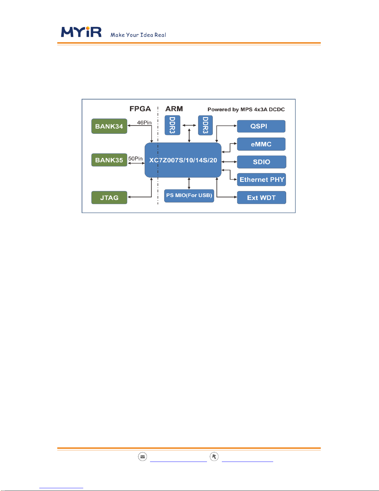
2.1 SOCBOARD RESOURCES...................................................................................................................................... 4
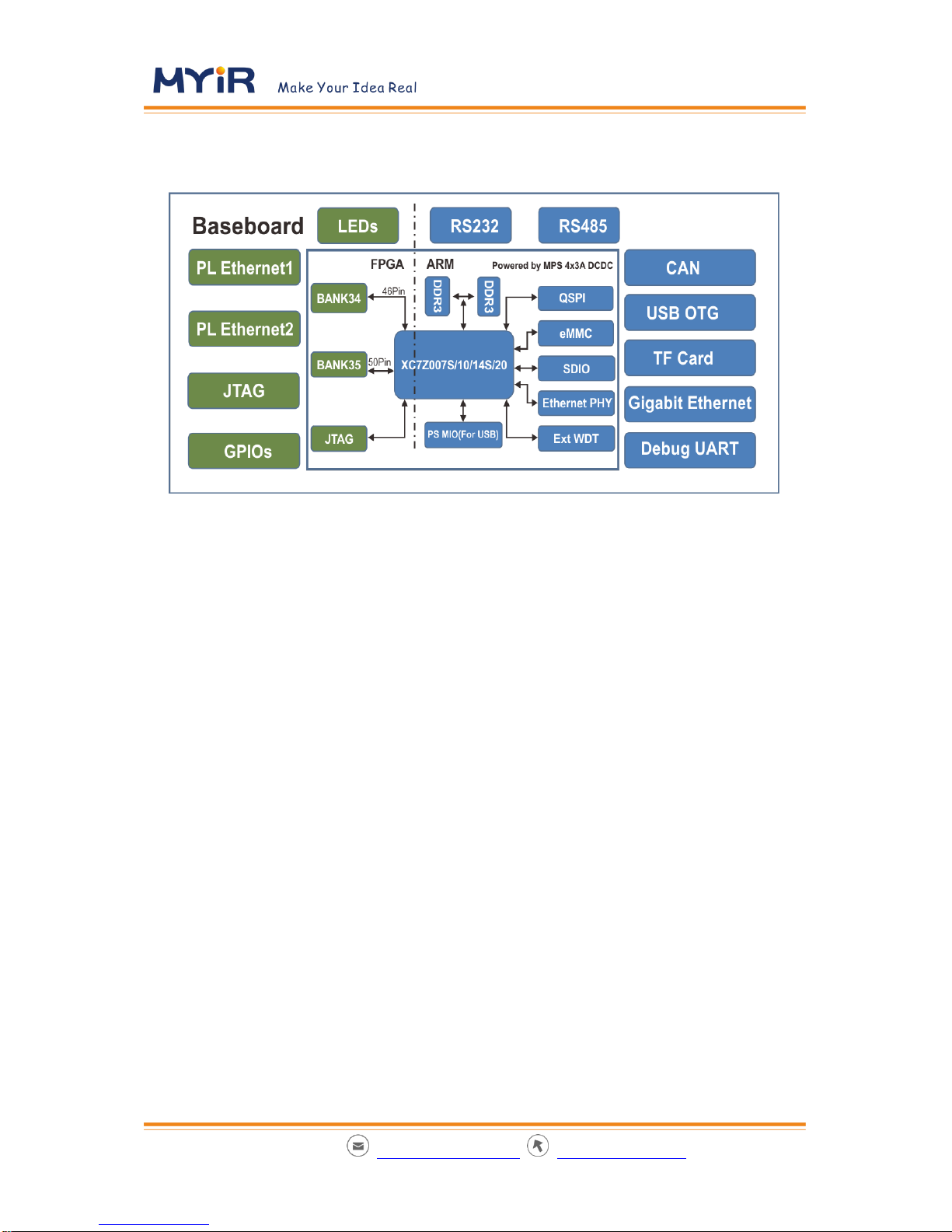
2.2 BASE BOARD RESOURCES..................................................................................................................................... 5
CHAPTER 3 HARDWARE INTRODUCTION .......................................................................................................... 6
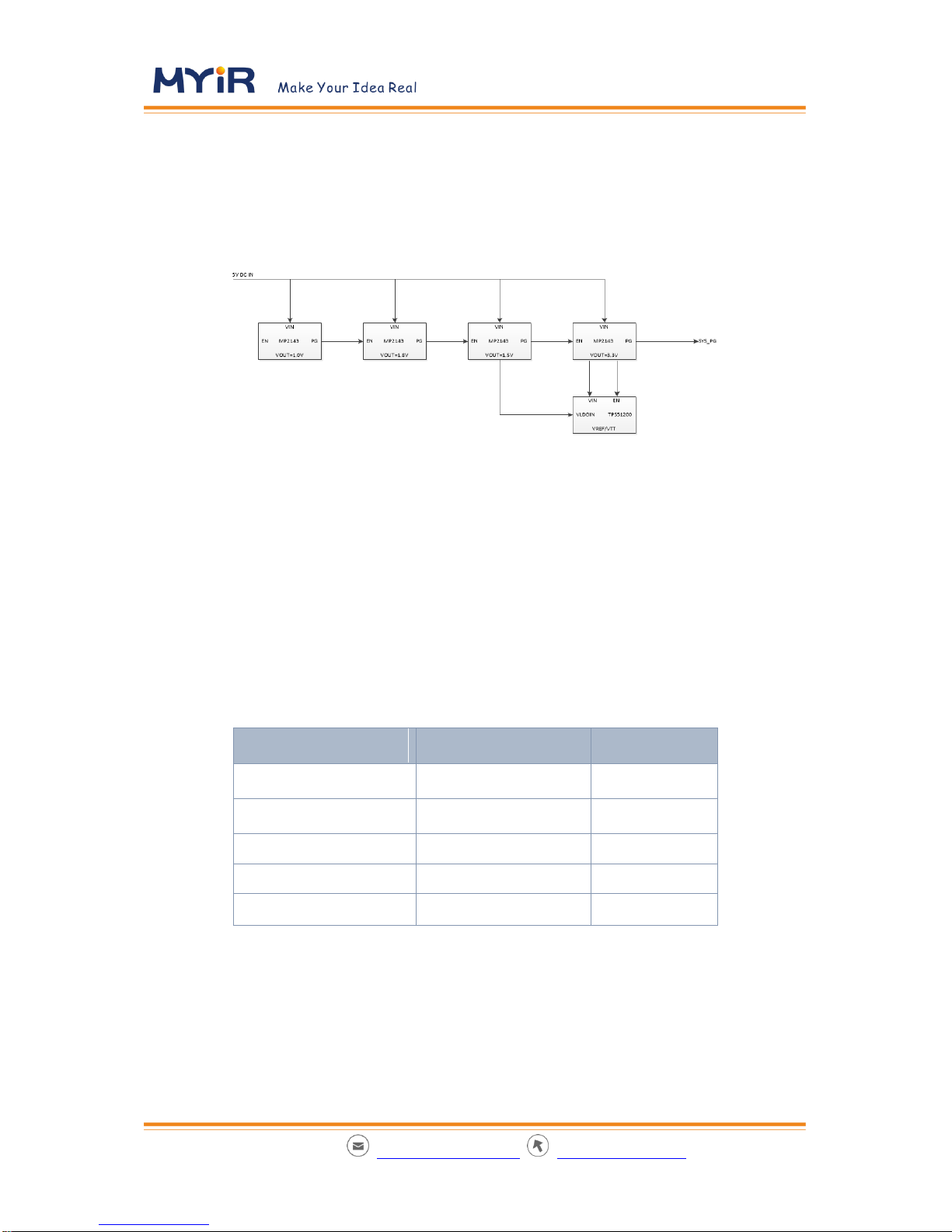
3.1 POWER ............................................................................................................................................................ 6
3.2 BOOT MODE SETTING......................................................................................................................................... 6
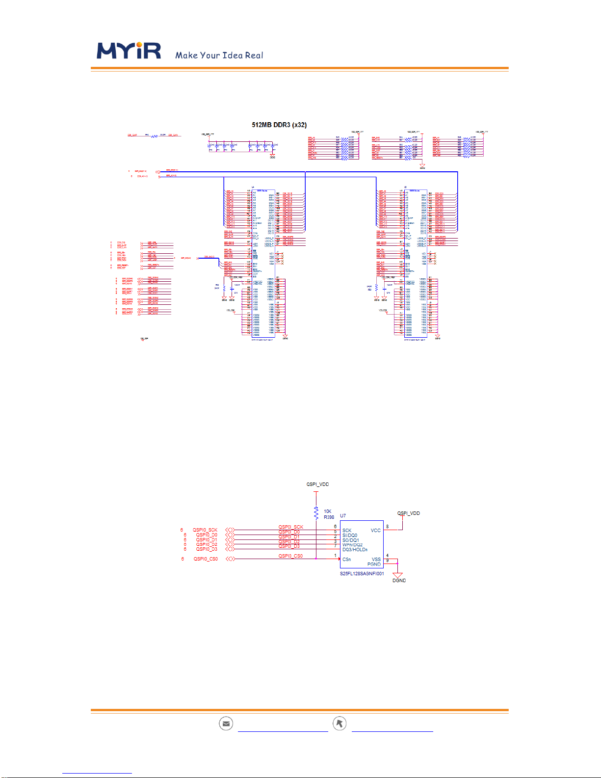
3.3 DDR ............................................................................................................................................................... 7
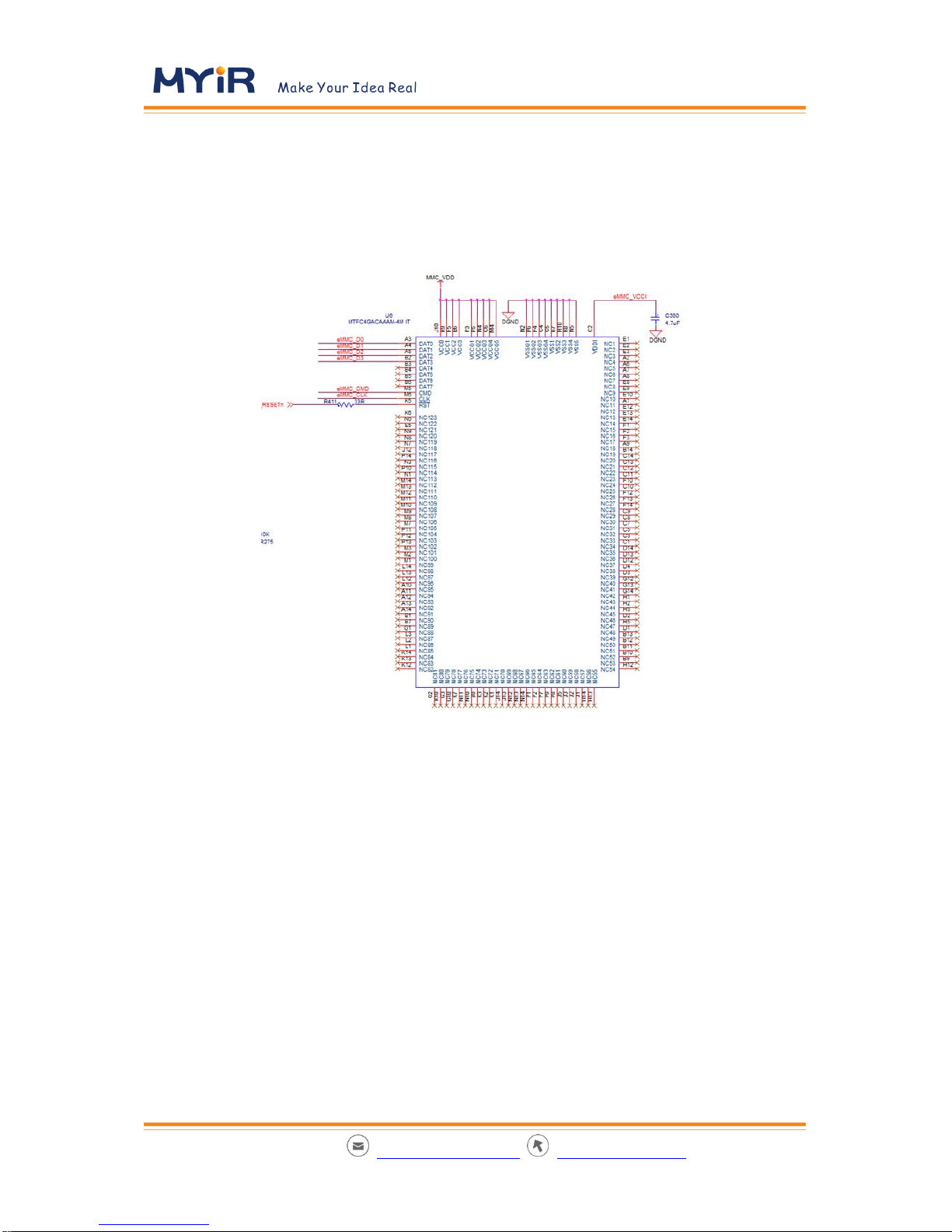
3.4 STORAGE .......................................................................................................................................................... 7
3.4.1 SPI Flash ................................................................................................................................................. 7
3.4.2 eMMC .................................................................................................................................................... 8
3.5 ETHERNET......................................................................................................................................................... 9
3.6 USB ................................................................................................................................................................ 9
3.7 WATCHDOG AND RESET….................................................................................................................................... 9
CHAPTER 4 HARDWARE.................................................................................................................................. 11
4.1 INTERFACE ...................................................................................................................................................... 11
4.2 PS INTERFACE.................................................................................................................................................. 11
4.2.1 Ethernet ............................................................................................................................................... 11
4.2.2 USB....................................................................................................................................................... 12
4.2.3 CAN/RS232/RS485 ............................................................................................................................... 12
4.2.4 Debug UART ......................................................................................................................................... 12
4.2.5 PressButton.......................................................................................................................................... 12
4.2.6 JTAG ..................................................................................................................................................... 12
4.2.7 TF card ................................................................................................................................................. 12
4.3 PL INTERFACE.................................................................................................................................................. 12
4.3.1 PL Ethernet........................................................................................................................................... 12
4.3.2 GPIO Port ............................................................................................................................................. 12
CHAPTER 5 SOFTWARE RESOURCE ................................................................................................................. 14
5.1 LINUX RESOURCES............................................................................................................................................ 14
5.2 LOGIC RESOURCES ............................................................................................................................................ 15
CHAPTER 6 MECHANICAL PARAMETERS ......................................................................................................... 16

MYD-Y7Z010/007S Development Board Hardware User Guide
APPENDIX I DISCLAIMER ................................................................................................................................ 17
APPENDIX II TECHNICAL SUPPORT AND WARRANTY ...................................................................................... 18
APPENDIX III CONTACT US .............................................................................................................................. 23

MYD-Y7Z010/007S Development Board Hardware User Guide
Chapter 1 Overview
1.1 Product Description
MYD-Y7Z010/007S is composed of the coreboard named MYC-Y7Z010/007S and the baseboard
named MYB-Y7Z010/007S. The coreboard (MYC-Y7Z010/007S) uses Xilinx Zynq-7000 series All
Programmable SoC 7Z007S/7Z010, which integrate single/dual core ARM Cortex-A9 and FPGA,
built on a state-of-the-art, high-performance, low-power (HPL), 28 nm, and high-k metal gate
(HKMG) process technology. Single/Dual core ARM Cortex-A9 provides high performance, and
ease of use, and FPGA offers flexibility and scalability of programming logic. MYD-Y7Z010/007S
can satisfy a variety of applications.
1.2 Picture

MYD-Y7Z010/007S Development Board Hardware User Guide
Chapter 2 Hardware Resource
2.1 SoC Board Resources
512MB DDR3 SDRAM
4GB eMMC
Qual SPI Flash 16MB
10/100/1000Mb/s Ethernet
External watchdog
One power LED (Red), One FPGA programming done LED (Green) and One user LED
(Green)

MYD-Y7Z010/007S Development Board Hardware User Guide
2.2 Base Board Resources
PS Unit
1 channel Gigabit Ethernet
1 channel USB 2.0
1 channel TF Card
1 channel CAN
1 channel RS232
1 channel RS485
1 channel JTAG
1 System Reset Key
PL Unit
2 channel Gigabit Ethernet
1 50Pins GPIO Port

MYD-Y7Z010/007S Development Board Hardware User Guide
Chapter 3 Hardware Introduction
3.1 Power
This figure shows the power sequence of power supplys on board. By Cascading Power Good
signal to Enable signal, the system powers in sequence: 1.0V-> 1.8V-> 1.5V-> 3.3V. The 3.3V is
enabled last, and then the power module produces a reset signal to SoC.After the reset signal is
deasserted, system starts to run.
3.2 Boot Mode Setting
The core board boots in QSPI mode by default. Users can set the Jumpers (Boot_JP1 and
Boot_JP2) to boot in SD card mode or JTAG mode.
Name
BOOT_JP1
BOOT_JP2
SOM Pin
C19
C20
SoC Pin
PS_MIO4
PS_MIO5
JTAG Boot mode
L
L
QSPI Boot
L
H
SD Card Boot
H
H
Table 5-1

MYD-Y7Z010/007S Development Board Hardware User Guide
3.3 DDR
The Core Board uses two 128Mx16 DDR3 chips, total 512MB by default, and the maximum
memory size supported is up to 1GB. The DDR controller is 32bit data bus, resides in PS BANK
502.
3.4 Storage
3.4.1 SPI Flash

MYD-Y7Z010/007S Development Board Hardware User Guide
The Core Board uses a 16MB Quad-SPI Flash W25Q128FVEIG, can be used to boot SoC,
initialize PS and configure PL. The interface is PS_SPI0, resides in PS BANK500 MIO[1-6].
3.4.2 eMMC
The Core Board uses a 4GB emmc chip, which can be used to store system files or other data,
and can be used as secondary boot device to boot system together with QSPI flash. The interface
is PS_SDIO1, resides in PS BANK500 MIO[10-15].

MYD-Y7Z010/007S Development Board Hardware User Guide
MYIR Electronics Limited | sales@myirtech.com www.myirtech.com 9/ 23
3.5 Ethernet
The Giga bit Ethernet Port is implemented by connecting PS MAC0 to external Ethernet PHY chip
KSZ9031RN. PS MAC0 resides in PS BANK501 MIO[16-27].
3.6 USB
By using an external USB Phy USB3320 on baseboard, the PS USB1 controller can implement
USB 2.0 OTG. The PS USB1 controller interface resides in PS BANK501 MIO[28-39].
3.7 Watchdog and Reset…
External watchdog chip is CAT823TTDI-GT3, and the feed pin WDT is connected to GPIO

MYD-Y7Z010/007S Development Board Hardware User Guide
MYIR Electronics Limited | sales@myirtech.com www.myirtech.com 10 / 23
PS_MIO0. External watchdog can be disabled by disconnecting the WDT pin.

MYD-Y7Z010/007S Development Board Hardware User Guide
MYIR Electronics Limited | sales@myirtech.com www.myirtech.com 11 / 23
Chapter 4 Hardware
4.1 Interface
Num
Description
J1
Power Port
J4,J11
Ethernet Port(1 PS Ethernet + 2 PL Ethernet)
J5
DB9 Female Port(RS232/RS485/CAN)
J6
JTAG Port
J7
50Pin 2.54mm-Pin-pitch Port
J8
3.3V UART Debug Port
J9
USB Port
J10
TF Card
D31
Combination LED
SW1
Boot setting Switch
S1
System Reset Key
4.2 PS Interface
4.2.1 Ethernet
1 Channel 10/100/1000Mbps Ethernet is implemented in the PS. Four pairs of Gigabit differential
signals coming out of PHY chip connected to the J4 on baseboard. J4 is a RJ45 block with a
transformer integrated.

MYD-Y7Z010/007S Development Board Hardware User Guide
MYIR Electronics Limited | sales@myirtech.com www.myirtech.com 12 / 23
4.2.2 USB
1 Channel USB 2.0 high speed interface is implemented by using a USB PHY USB3320C on
baseboard, and the Port is J9.
4.2.3 CAN/RS232/RS485
1 CAN, 1 RS232, and 1 RS485 are routed out through DB9 J5.
4.2.4 Debug UART
1 Channel 3.3V UART Port J5 is used as debug serial port.
4.2.5 PressButton
1 PressButton is located on baseboard used for system reset.
4.2.6 JTAG
1 14Pins JTAG Port is used for PS/PL debug.
4.2.7 TF card
1 TF card is used for data storage and can be also used as boot device.
4.3 PL Interface
4.3.1 PL Ethernet
2 another ethernt ports are expanded from PL, can be used for real-time industrial ethernet
communication.
4.3.2 GPIO Port
1 50Pins GPIO Port is located on baseboard for customized applications..

MYD-Y7Z010/007S Development Board Hardware User Guide
MYIR Electronics Limited | sales@myirtech.com www.myirtech.com 13 / 23

MYD-Y7Z010/007S Development Board Hardware User Guide
MYIR Electronics Limited | sales@myirtech.com www.myirtech.com 14 / 23
Chapter 5 Software Resource
5.1 Linux Resources
Category
Name
Remark
Code
Tool
chains
gcc 4.6.1
gcc version 4.6.1
(Sourcery CodeBench Lite 2011.09-50)
Boot
loader
BOOT.BIN
First bootstrap Include FSBL and u-boot
Yes
Linux
Kernel
Linux 3.15.0
Linux kernel customized for MYD-Y7Z010/007S
hardware
Yes
Driver
USB Host
USB Host driver
Yes
PS MIO Ethernet
Gigabit Ethernet driver
Yes
PS EMIO Ethernet
driver for vivado reference design we offered
Yes
PL AXI Ethernet
driver for vivado reference design we offered
Yes
MMC/SD/TF
MMC/SD/TF Card driver
Yes
CAN
CAN driver
Yes
LCD Controller
LCD screen driver for our vivado display
reference design
Yes
HDMI
driver for SII902X and our vivado display
reference
Yes
Button
Button driver
Yes
UART
Serial driver
Yes
LED
LED driver
Yes
GPIO
GPIO driver
Yes
QSPI
QSPI Flash W25Q128FW driver
Yes
Capacitive Touch
FT5X0XCapacitive Touch driver
Yes
XADC
XADC driver
Yes
File
system
Ramdisk
Ramdisk image
Yes
Rootfs
Made by buildroot
Yes
Table 5-1

MYD-Y7Z010/007S Development Board Hardware User Guide
MYIR Electronics Limited | sales@myirtech.com www.myirtech.com 15 / 23
5.2 Logic Resources
Type
Name
Remark
Logic
Peripherals
HDMI
All IP cores used in the reference design is offered
by Xilinx.
LCD
All IP cores used in the reference design is offered
by Xilinx.
Two
1000M
Ehernet
extension
All IP cores used in the reference design is offered
by Xilinx.
Table 5-2

MYD-Y7Z010/007S Development Board Hardware User Guide
MYIR Electronics Limited | sales@myirtech.com www.myirtech.com 16 / 23
Chapter 6 Mechanical parameters
Operating Temperature:
-40~+85 Celsius, Industrial grade( compliancewith CE, FCC, CCC)
Humidity: 20%~90%
Power Supply:
Core Board : 5V
MYD-Y7Z010/007S : 12V
Footprint: 180 Pin / 1.27mm pin-pitch
PCB:
Base Board: 4 Layer, Immersion Gold, Lead free
Core Board: 10 Layer, Immersion Gold, Lead free
Dimensions:
Base Board: 153mm x 80 mm
Core Board: 75mm x 50 mm

MYD-Y7Z010/007S Development Board Hardware User Guide
MYIR Electronics Limited | sales@myirtech.com www.myirtech.com 17 / 23
Appendix I Disclaimer
This User Manual (the "Manual") is proprietary to MYIR Electronics Limited. ("MYIR") and no
ownership rights are hereby transferred. No part of the Manual shall be used, reproduced,
translated, converted, adapted, stored in a retrieval system, communicated or transmitted by any
means, for any commercial purpose, including without limitation, sale, resale, license, rental or
lease, without the prior express written consent of MYIR.
MYIR does not make any representations, warranties or guarantees, express or implied, as to the
accuracy or completeness of the Manual. Users must be aware that updates and amendments
will be made from time to time to the Manual. It is the user's responsibility to determine whether
there have been any such updates or amendments. Neither MYIR nor any of its directors, officers,
employees or agents shall be liable in contract, tort or in any other manner whatsoever to any
person for any loss, damage, injury, liability, cost or expense of any nature, including without
limitation incidental, special, direct or consequential damages arising out of or in connection with
the use of the Manual.

MYD-Y7Z010/007S Development Board Hardware User Guide
MYIR Electronics Limited | sales@myirtech.com www.myirtech.com 18 / 23
Appendix II Technical Support and Warranty
MYIR Electronics Limited (“MYIR”) is a global provider of ARM hardware and software tools,
design solutions for embedded applications. We support our customers in a wide range of
services to accelerate your time to market.
MYIR is an ARM Connected Community Member and work closely with ARM and many
semiconductor vendors. We sell products ranging from board level products such as development
boards, single board computers and CPU modules to help with your evaluation, prototype, and
system integration or creating your own applications. Our products are used widely in industrial
control, medical devices, consumer electronic, telecommunication systems, Human Machine
Interface (HMI) and more other embedded applications. MYIR has an experienced team and
provides custom design services based on ARM processors to help customers make your idea a
reality.
The contents below introduce to customers the warranty and technical support services provided
by MYIR as well as the matters needing attention in using MYIR’s products.
Service Guarantee
MYIR regards the product quality as the life of an enterprise. We strictly check and control the
core board design, the procurement of components, production control, product testing,
packaging, shipping and other aspects and strive to provide products with best quality to
customers. We believe that only quality products and excellent services can ensure the long-term
cooperation and mutual benefit.
Price
MYIR insists on providing customers with the most valuable products. We do not pursue excess
profits which we think only for short-time cooperation. Instead, we hope to establish long-term
This manual suits for next models
1
Table of contents
Other MYiR Motherboard manuals