Myriad Design Altoids Piezo DI Instructions for use

Page 1 of 6
Myriad Design – Altoids Piezo DI – Construction Guide
V2 December, 2014
1. The package should include the follo ing items. If any of the items are missing from the package,
please contact sales@stompville.co.uk :
Designation Description Marking
PCB Altoids1 Piezo DI - printed circuit
board
APDV4DS06
R1, R5, R6 1/8W resistor - 10k See Note 2
R2 1/8W resistor - 10M
R3 1/8W resistor - 4k7
R4 1/8W resistor - 1M0
R7, R8 1/8W resistor - 33R
R9, R10 1/8W resistor - 1k0
R11 1/4W resistor - 10R
R12 1/8W resistor - 180k
R13 1/8W resistor - 120k
R14 1/8W resistor - 220k
R15 1/8W resistor - 150k
R16 1/8W resistor - 3k6
C1, C6 22p ceramic 22
C2 470p ceramic 470
C3 47n polyester box 47n or .047
C4, C5, C9, C12,
C13
100n polyester box 100n or .1
C7, C8 47u 50V electrolytic
C10, C10, C11,
C11
100u 50V electrolytic
C14 10n ceramic 10n or 103
D1, D2, D3, D4 1N4148 diode 1N4148
D5 BZX55C33V BZX55C33
Q1, Q2 PF5102 JFET matched pair PF5102
U1 LM833 dual op-amp LM833
U2 TC54VN2902EZB voltage detector 54VN2902
LED1 3mm red LED
- Battery Clip
J1, J2 1/4” stereo jack socket CL11155
SW1 push-on push-off s itch
- 8-pin DIL socket
- green ire
- card ith self-adhesive tape/foam
- self adhesive foam pad
- M3 x 6 pozi pan machine scre
- M3 brass nut
- label for underside of Altoids tin
- template dra ing for cutting holes
- quick start guide
1 Altoids is a trademark of the Wrigley Company. Their rights are hereby ackno ledged.
2 Some resistors may be 4-band and some 5-band. See: http://stompville.co.uk/ResistorColourCodes.pdf
2. It is assumed that you have some experience of soldering and building of simple kits and are
confident to build or modify effects pedals. If not, there are many relevant tutorials and videos on

Page 2 of 6
the internet. Please spend some time familiarising yourself ith construction and soldering
techniques.
3. Note that Q1, Q2, D1~ D5, U1 and U2 are electrostatic sensitive devices and should be handled
ith care. If you have an ESD protective ristband, use that. If not, ear clothes made of natural
materials (e.g. cotton), regularly touch your finger to an earthed (grounded) metal object (such as a
radiator) and do not handle the sensitive devices any more than you have to. In particular, don’t
remove them from the electrostatic protective package until you are ready to fit them to the board.
4. Solder the items to the PCB according to the silk-screen legend, checking and ensuring that you
insert each component in the correct orientation.

Page 3 of 6
5. Note that if you are not using an Altoids tin as an enclosure and you ish to have a volume control
on the output, then omit LK3 and fit a potentiometer (not supplied) to the VR1 connections. The
clock ise end of the potentiometer is marked on the PCB “CW”.
6. Note that LK2 is fitted after the battery clip has been soldered in - and serves to act as a strain
relief.
7. Note that the LED must be connected the correct ay round. The shorter lead of the LED is the
cathode and is sho n by the flat side of the PCB legend. If you have cut the leads of the LED and lost
track of hich as the shorter lead, look ‘inside’ the LED – the cathode is the larger of the t o
internal structures (note that this is not a universal rule).
8. There is no compelling reason to cut the green earth ire short and you ill find it easier to solder
the ire to the enclosure if you leave the green ire fairly long.
9. You may ish to test the board before installing it in the enclosure. The input and output sockets
are clearly marked on the board. The battery is not connected to the circuit until there is a plug in the
input socket. Connect the input to an instrument ith a piezo transducer (or indeed any instrument,
including electro-acoustic guitar, electric guitar, bass guitar, or even a keyboard, etc). Connect the
output to a mixing desk ith phantom po er. With the s itch in the ‘out’ position, the unit ill be
phantom po ered. With the s itch in the ‘in’ position, the unit ill be battery po ered.
Enclosure
10. Carefully remove the lid of the Altoids tin by bending back the hinge tabs. Cut out the template
and stick it on to the tin ensuring that the template is centred. Cut out the holes for the s itch, LED
and Jack sockets. Take care cutting the larger holes as a normal 10mm HSS Drill bit ill likely tear
the thin metal. The use of a stepped sheet-metal drill (Google: step drill) or a Q-max chassis punch
(Google: q-max 10mm) is recommended. Refit the lid and drill a 3mm hole half ay along the lid-
flange at the front for the scre .

Page 4 of 6
11. Remove the lid again and scre the nut and scre through the tin. Solder the nut to the case.
Note that a 25W soldering iron ith a 3mm or larger tip is adequate.
12. Remove the bro n cover tape from the underside of the cardboard insulator and carefully fit it to
the bottom of the tin. The foam pad should be at the end opposite to the holes. There is no need to
remove the backing paper from the top of the foam pad – if you stick the battery do n to the pad, it
ill be useless hen you change the battery.
13. Carefully solder the end of the green ire to the inside of the tin. Note that the accompanying
photo sho s a black ire in lieu of the green ire supplied.
14. If you have not already done so, carefully clip all the protruding pins on the rear of the circuit
board. In particular, the pins on the sockets should be trimmed back as short as possible. You can use
the supplied sticky foam pad to stick the board do n (as sho n in the photograph belo ), but long-
term experience is that you ill be better off gluing the board in place ith a little hot-glue, silicone
or instant-grab adhesive.
15. Fit the lid and bend the tabs back in place to ensure the lid stays on at the hinge side. Fit the
battery, allo ing the battery ire to fall across the top of the battery. Close the lid and fit the scre .
Lightly shake the unit; the battery should not rattle around.
16. Carefully apply the sticker to the underside of the tin.

Page 5 of 6

Page 6 of 6
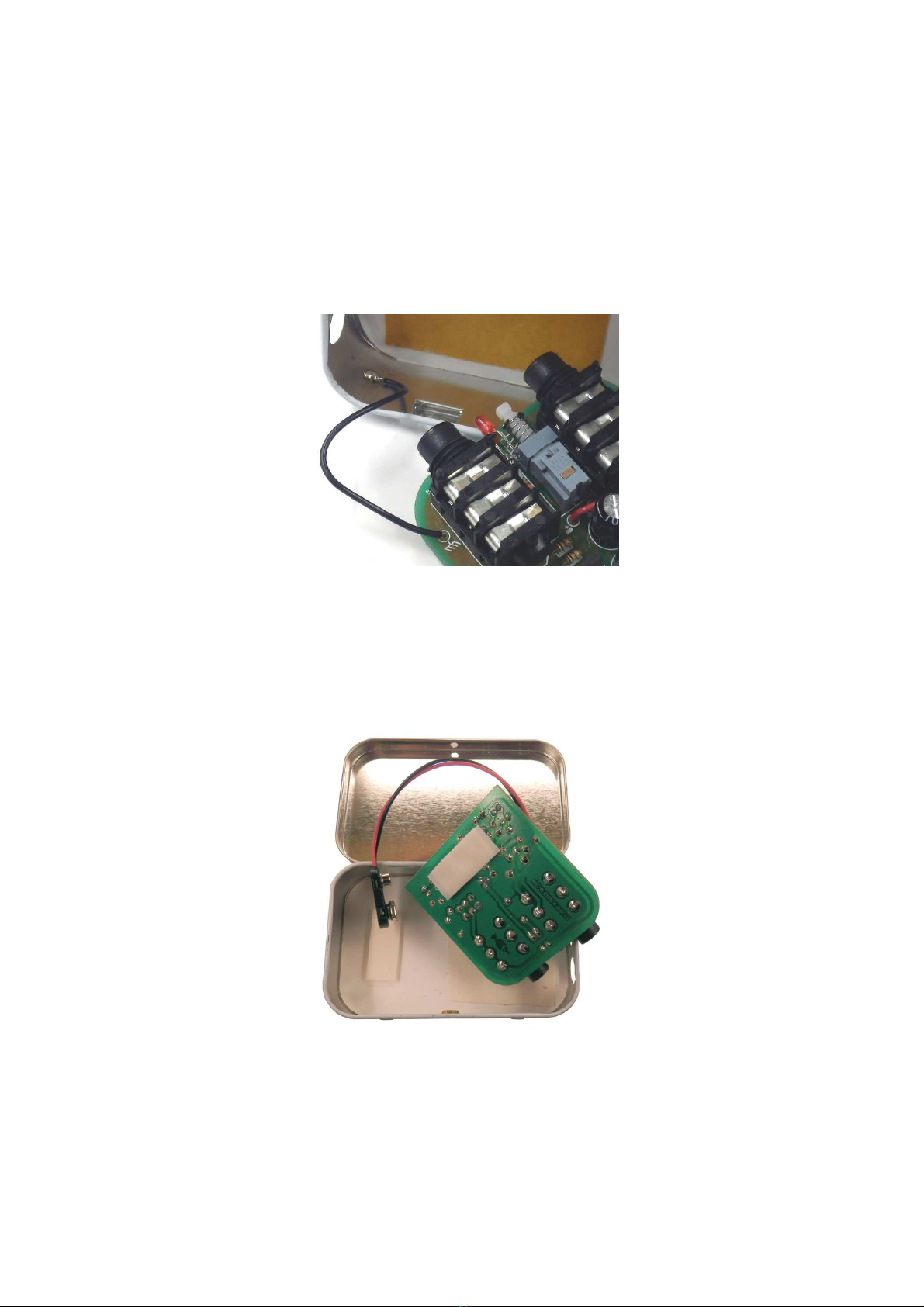
17. Note: the reason a stereo jack socket as used on the input side is so that the unit may be
s itched off hen the input cable is removed.
18. Note: the po er consumption of the unit is a fe milliamps. This means that a fresh alkaline
battery ill last a fe eeks to a fe months of moderate use. Try to po er the unit from a phantom-
po ered mixing desk if possible.
19. You ill need to make/buy a special output lead for this unit. I suggest a length of about 2 metres
ith a stereo ¼” jack plug one end and a 3-pin male XLR the other end. Connect the tip to pin 2, the
ring to pin 3 and the sleeve to pin 1. You should then tell the sound guy that you need a microphone
lead ith phantom po er for your preamp DI. Keep the short custom lead ith the unit so you
al ays have it herever you go to gig. Alternatively, you can make the lead as long as you like (i.e. to
go straight to the mixing desk), or make a very short adapter lead, but if you make the lead too short,
the eight of the cable ith t o XLRs dangling off your back pocket (assuming that’s here you stash
your unit hen in use) can be a little annoying.
Using the Preamp DI
20. The preamp has very high input impedance. This makes it suitable for passive piezo pickups
hich may be built-into or added on to stringed or percussion instruments. Generally speaking the
cable bet een the pickup and the instrument should be as short as practical - if you are a violin player
you should consider having a lead from your pickup just long enough to comfortably reach the
preamp if the preamp is in the back pocket of your jeans or in a pouch slung over the shoulder. The
output cable can then be as long as it needs to be to reach the mixing desk or mixer-amp.
21. The preamp may also be used ith other types of pickup. For example, you can use it to DI an
electro-acoustic guitar or even a keyboard. In fact you can think of it as a general purpose instrument
D.I. ith the caveat that the DI needs ideally to have a short lead to the instrument.
22. You should disconnect the input cable hen the preamp is not in use as this ill disconnect the
battery and conserve battery life (this is obviously not important for phantom po er use). When the
battery voltage drops (from 9V) to about 7.3V the LED ill illuminate. As the consumption is fairly
high (several mA) you should replace the battery (or s itch to phantom po er) as soon as you notice
the light coming on. Note that the lo battery light ill come on even if you are on phantom po er,
so you may not need to orry. If you’re al ays going to be on phantom po er, you can omit the
battery altogether.
Copyright 2012-14 Myriad Design. All rights reserved.
Disclaimer.
The information contained herein is provided in good faith. Myriad Design has no control over the
standard of construction of this kit, nor any control over the ay the design is implemented or
integrated into a system. Therefore, Myriad Design offers no actual or implied arranty of fitness for
purpose and Myriad Design ill accept no liability for consequential loss or damage. This design is
not authorised for use in any safety-critical system. Your statutory rights are not affected.
Myriad Design · United Kingdom
.stompville.co.uk sales@stompville.co.uk

Table of contents
Other Myriad Design Amplifier manuals