N-Vision Optics ATLAS User manual

N-Vision Optics LLC
____________________________________________________________________________
220 Reservoir Street, Suite 26, Needham, MA 02494
781-505-8360
OPERATOR’S MANUAL
Thermal Binocular
ATLAS
Revision 2.39 March 2017
© 2017 Copyright N-Vision Optics LLC All rights reserved

TABLE OF CONTENTS
TABLE OF CONTENTS............................................................................................................. 1
LIST OF FIGURES .................................................................................................................... 2
LIST OF TABLES....................................................................................................................... 2
General Information................................................................................................................... 3
Scope..................................................................................................................................... 3
Models.................................................................................................................................... 3
Introduction............................................................................................................................. 3
Safety Summary..................................................................................................................... 4
Warnings ................................................................................................................................ 4
Unit Overview ............................................................................................................................ 5
Features ................................................................................................................................. 5
Key Specifications .................................................................................................................. 6
ATLAS Components .................................................................................................................. 7
Standard Kit............................................................................................................................ 8
Operation................................................................................................................................... 8
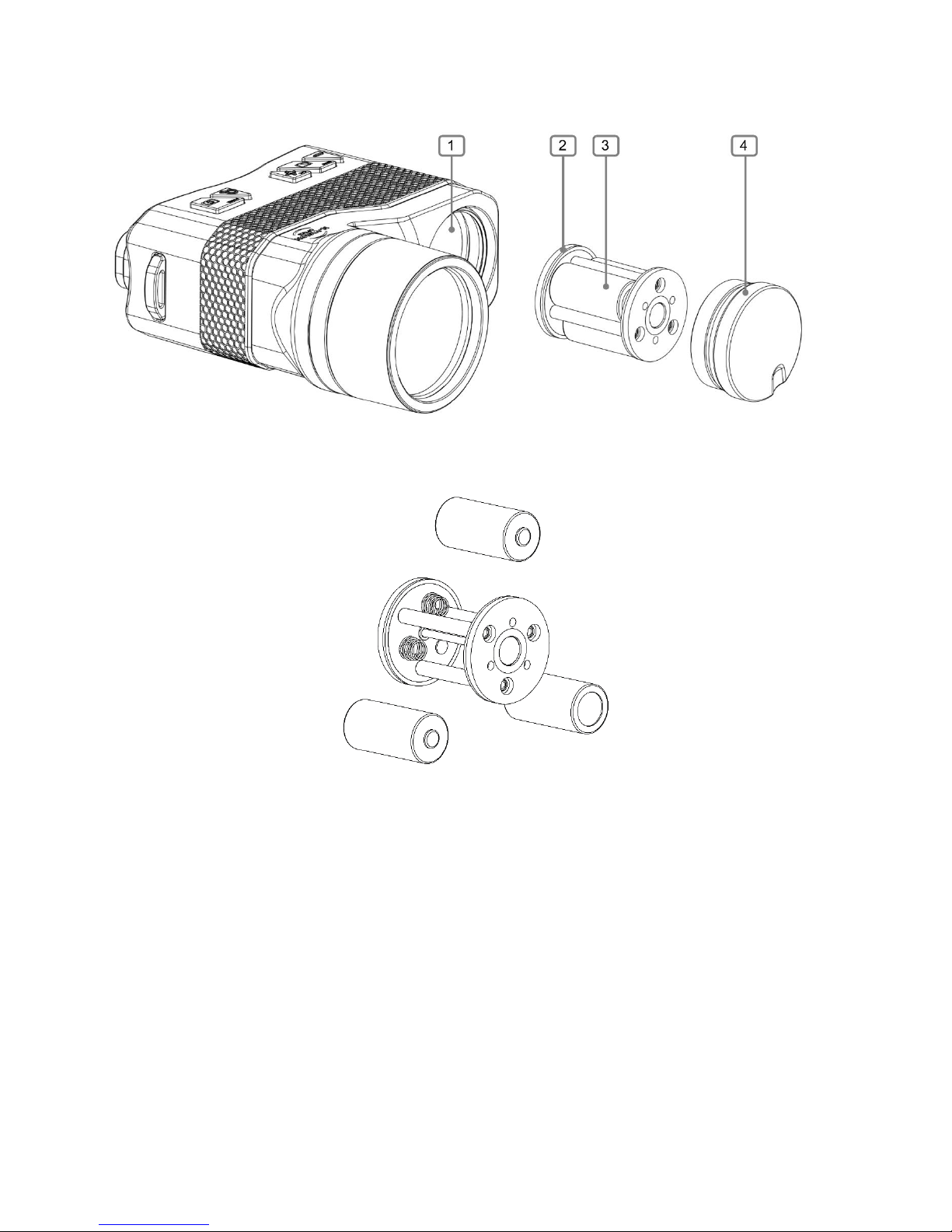
Installing Batteries .................................................................................................................. 8
Switching the Unit ON and OFF.............................................................................................10
Thermal Calibration ...............................................................................................................10
Focusing................................................................................................................................10
Diopter Adjustment................................................................................................................11
Operating Modes and Menus.................................................................................................11
ATLAS Control Switches...........................................................................................................12
Normal Mode Description..........................................................................................................13
Taking Photos........................................................................................................................13
Zoom.....................................................................................................................................13
Polarity ..................................................................................................................................14
Contrast Enhancement (CE) Adjustment ...............................................................................14
Menu Mode Description............................................................................................................14
Navigation in Menu Mode......................................................................................................15
Main Menu.............................................................................................................................15
System Settings Menu...........................................................................................................16
Video Settings Menu..............................................................................................................16
System Info Menu..................................................................................................................17
Gallery...................................................................................................................................18
Maintenance Instructions..........................................................................................................18
Introduction............................................................................................................................18
Preparing for Maintenance.....................................................................................................18
Cleaning the ATLAS ..............................................................................................................18
Cleaning the Optics ...............................................................................................................18
Checking for Damage and Corrosion.....................................................................................18
Description of Additional Functions...........................................................................................19
Electrical Interface.................................................................................................................19
Troubleshooting........................................................................................................................21

LIST OF FIGURES
Figure 1. ATLAS Thermal Binocular.......................................................................................... 3
Figure 2. ATLAS Thermal Binocular.......................................................................................... 5
Figure 3. ATLAS Front View...................................................................................................... 7
Figure 4. ATLAS Rear View...................................................................................................... 7
Figure 5. ATLAS with Removed Battery Cartridge .................................................................... 9
Figure 6. Inserting Batteries Into Batteries Cartridge................................................................. 9
Figure 7. ATLAS Control Switches...........................................................................................10
Figure 8. ATLAS Control Switches...........................................................................................12
Figure 9. ATLAS Electrical Connector......................................................................................19
Figure 10 Optional ATLAS Cable.............................................................................................19
LIST OF TABLES
Table 1. Key Specifications....................................................................................................... 6
Table 2 Functionality of Switches in Different Modes ...............................................................12
Table 3 6-Pin Electrical Connector...........................................................................................20
Table 4 Troubleshooting Instructions .......................................................................................21

General Information
You must familiarize yourself with the entire manual before operating the equipment. Read the
complete manual and follow all WARNINGS and NOTES. Study this manual carefully and
understand all related safety precautions.
Scope
This manual provides the user with information related to operations, maintenance, and
troubleshooting of the thermal binoculars ATLAS.
Models
Figures 1 represents the thermal binocular ATLAS.
Figure 1. ATLAS Thermal Binocular
Introduction
ATLAS is an uncooled universal thermal binocular detecting the long IR part of the spectrum (7.5
- 13.5 μm) and designed to meet the demands of security professionals, nature enthusiasts,
sailors, hunters, and sportsmen alike. ATLAS offers unsurpassed performance when used for
search and rescue operations, surveillance, perimeter control, and vehicle identification in
addition to a wide variety of other applications.
The rugged and lightweight ATLAS combines an engineered plastic housing with optics that will
satisfy the most stringent and demanding requirements. Regardless of ambient light conditions,
smoke or haze, ATLAS detects even the slightest temperature differences of everything in the
field of view and provides the user with clear “white hot”, “black hot”, colored or “edge-detected”

images of what would otherwise be invisible to the naked eye.
Safety Summary
ATLAS is a precision electro-optical instrument and must be handled carefully at all
times to prevent damage.
To protect ATLAS from unnecessary damage and degradation of performance never
point the unit at extremely hot objects, such as the bright sun or a hot, burning fire.
Do not scratch the lens surfaces.
Be careful not to touch the lens surfaces. To remove contamination or fingerprints use
lens paper to carefully clean the surface of the objective lens.
Do not carry batteries in pockets containing metal objects such as keys, coins, sharp
tools, etc. Those objects can damage batteries and short-circuit them. Shorted batteries may
become very hot and could potentially cause bodily harm.
Warnings
THE THERMAL IMAGING SENSOR USED WITHIN THE ATLAS IS VERY SENSITIVE TO
EXPOSURE TO EXTREMELY HIGH LEVELS OF RADIANT FLUX (HEAT).
NEVER EXPOSE ATLAS, EITHER TURNED ON OR OFF, DIRECTLY TO THE SUN OR ANY
OTHER SOURCE OF HEAT THAT THE HUMAN EYE CANNOT TOLERATE. EXPOSURE TO
THE HIGH LEVEL OF RADIATION MAY DAMAGE THE ATLAS THERMAL SENSOR.
KEEP THE OBJECTIVE LENS COVER CLOSED AT ALL TIMES WHEN THE ATLAS IS NOT
IN USE.
INADVERTENT SUN DAMAGE IS NOT CONSIDERED A DEFECT IN MATERIAL OR
WORKMANSHIP, AND IS NOT COVERED IN THE PRODUCT WARRANTY.

Unit Overview
Figures 2 below shows the ATLAS thermal binocular.
Figure 2. ATLAS Thermal Binocular
Features
Long range observation regardless of available ambient light
Black Hot/White Hot polarity selection
Color Pallet
Edge Detect mode
Digital 2x and 4x zoom
High resolution throughout the entire field of view
Nitrogen purged in order to prevent internal fogging and extend service life
State of the art impact-resistant rubberized engineered plastics housing

Key Specifications
Key specifications are presented below in Table 1. Model specific characteristics can be found
on product specification sheets or by contacting N-Vision Optics.
Table 1. Key Specifications
Sensor type
Uncooled vanadium oxide (VOx)
microbolometer
Detector resolution
640 x 480
Spectral response, µm
7.5 - 13.5
Detector pitch, µm
12
Refresh rate, Hz
60 or 9 (International Model)
Start-up time, sec
< 5
Objective lens
50mm F1.2
FOV, degree
9 Horizontal, 7 Vertical
Focus
Manual
Detection, man size target, m
2250 (60% Detection Probability)
Recognition, man size target, m
820 (60% Recognition Probability)
Identification, man size target, m
430 (60% Identification Probability)
Analog output
NTSC or PAL
Output resolution, NTSC
640 x 480
Output resolution, PAL
768 x 574
Power, internal
Three CR123 (DL123) batteries
Power, external
USB
Display
Color
Display resolution
800 x 600
Diopter adjustment, diopters
Fixed 0-diopters
Size (L x W x H) cm / in
14.8 / 5.8 x 12.4 / 4.8 x 61 / 2.4
Weight, grams / oz
575 / 20
Surface finish
Black
Operating temperature range, ºC
-40 to +50
Storage temperature range, ºC
-40 to +71
Internal Memory
60 Images

ATLAS Components
Figure 3. ATLAS Front View
Figure 4. ATLAS Rear View

Refer to Figures 3 and 4 to identify key components.
1. Objective Lens
2. Objective Lens Focusing Ring
3. ATLAS Housing
4. Power/Photo Switch
5. Zoom Switch
6. Contrast Enhancement (CE)+ / Cal Switch
7. Polarity/Menu/Select Switch
8. Contrast Enhancement (CE) - Switch
9. Battery Compartment Cover
10. Neck Strap Lug
11. Neck Strap Lug (not shown)
12. Eye Pieces
13. No-Slip Surface
Standard Kit
Standard ATLAS kit includes unit, carrying/storage case, lens cleaning paper, user manual,
battery cartridge, three (3) CR123 (DL123) size batteries.
Operation
Refer to Figures 3 and 4 to identify components.
Installing Batteries
WARNINGS:
DO NOT MIX OLD AND NEW BATTERIES. DO NOT MIX BRANDS OF BATTERIES. DO NOT
MIX DISPOSABLE AND RECHARGEABLE BATTERIES.
INSPECT BATTERIES FOR BULGING PRIOR TO USE. IF THE BATTERY SHOWS SIGNS OF
BULGING, DO NOT USE.
DO NOT DAMAGE, PUNCTURE, SHORT CIRCUIT, ATTEMPT TO RECHARGE OR
OTHERWISE TAMPER WITH BATTERIES. TURN OFF THE ATLAS IF THE BATTERY
COMPARTMENT BECOMES TOO HOT. IF POSSIBLE, WAIT UNTIL IT COOLS DOWN
BEFORE REMOVING BATTERIES.
ALWAYS REMOVE BATTERIES WHEN STORING OR SHIPPING THE ATLAS.
THE USE OF REPUTABLE BRAND NAME, HIGH QUALITY BATTERIES IS RECOMMENDED.
BATTERIES OF LESSER QUALITY MAY HAVE SIGNIFICANTLY SHORTER LIFE.

Figure 5. ATLAS with Removed Battery Cartridge
Figure 6. Inserting Batteries Into Batteries Cartridge
Refer to Figures 5 and 6 to identify components related to the battery compartment.
NOTE: Batteries in the ATLAS are placed in the Battery Cartridge (2). Battery Cartridge can be
inserted in the Battery Compartment either side forward.
Unscrew the Battery Compartment Cover (4) that is holding the Batteries Cartridge. Pull Battery
Cartridge (2) from the Battery Compartment Cover (4). Install three CR123 batteries (3) as shown
on Figure 6 into the Battery Cartridge (2). Inspect the rubber O-ring of the Battery Compartment
Cover (4) for damage. Replace if necessary. Slide Battery Cartridge (2) with installed batteries
into the Battery Compartment Cover (4). Screw Battery Compartment Cover (4) with Battery
Cartridge (2) holding batteries back into the Battery Compartment (1).

Figure 7. ATLAS Control Switches
For the following sections refer to the Figure 7 above.
Switching the Unit ON and OFF
To switch ATLAS on, press and hold Power/Photo switch (1) for three seconds. In order to turn
the unit off, press and hold Power/Photo switch (1) for approximately two seconds.
Thermal Calibration
ATLAS requires calibration before each use (after powering unit up), if image becomes sub-
optimal, or after significant change in ambient temperature. To calibrate the system, press and
hold the CE+ / Cal Switch (3) for approximately two seconds.
ATLAS supports two calibration modes Blade and Scene. Desired calibration mode is
selectable via the System Settings Menu (see below). At the factory, calibration mode is set to
Blade. In Blade mode, calibration at startup is performed automatically without any user input
by briefly closing the shutter located between image sensor and objective lens. The calibration
in Blade mode occurs automatically when system determines that calibration is necessary but
user can force calibration by pressing and holding CE+ / Cal Switch (3) for approximately two
seconds.
NOTE: Blade calibration, while very convenient and automatic, does not take into effect the
influence of the objective lens. In most cases it is not necessary, but if it appears that Blade
calibration does not produce sufficient results it may be necessary to switch ATLAS to Scene
calibration mode.
Scene calibration mode does not occur automatically and requires user to perform it manually.
To do Scene calibration (if enabled in System Settings Menu) press and hold the CE+ / Cal
Switch (3) for approximately two seconds while the objective lens is completely covered with
objective lens cover, a hand, etc.
Focusing
To focus objective lens on the object of interest, rotate Objective Lens Focusing Ring (2) on

Figure 3 until image is sharp.
Diopter Adjustment
NOTE: The Ocular (eyepiece) lens of the ATLAS is a fixed focus lens and does not require any
adjustments. It is set to zero diopters and can be used while wearing prescription eyewear or
contact lenses.
Operating Modes and Menus
ATLAS binocular has the following operating modes:
Normal Mode
Normal Mode is used for observation with ATLAS. When the user powers up the ATLAS
thermal binocular, Normal Mode is the default setting for the system.
Menu Mode
Menu Mode allows the user to conduct system configuration (choice of reticle, color, brightness,
etc.) and review some of the system’s parameters (part number and software version).
USB Mode
ATLAS will enter USB Mode when it is connected to the USB port of a Personal Computer (PC)
with an optional USB cable. When ATLAS is connected to the USB port of a PC, its core
electronics power up automatically, but the rest of the system remains off and there is no image
displayed through eyepieces. In this mode it is possible, using appropriate software on the PC,
to download images to the PC from the ATLAS unit and delete them from the ATLAS memory.
NOTE: It is possible to power up ATLAS using power from the computer’s USB port and start
the ATLAS in Normal Mode. In order to prevent ATLAS from going into USB Mode and,
instead, power up in Normal Mode, press down and hold Power button while connecting ATLAS
to the USB port. In this case it is still possible to download images to PC and delete them from
the ATLAS but image is visible through the eyepieces and device can be operated as normal.

ATLAS Control Switches
Figure 8. ATLAS Control Switches
Table 2 below provides descriptions of the switch functionality in different modes. Refer to
Figure 12 above to identify the switches.
Table 2 Functionality of Switches in Different Modes
Normal Mode
Individual Functions
Switch
Function
(Marking)
Description
1
Power / Photo
(POWER)
Powers unit up if pressed and held for three seconds.
Powers unit down if pressed and held for two
seconds.
Takes picture if pressed and released quickly. This
only works if Enable Photo in Normal Mode is set to
YES in Settings.
2
Digital Zoom
(Magnifying
Glass)
Cycles digital zoom settings (1X, 2X, 4X).
3
CE+ / Cal Switch
(+)
Increases the Contrast Enhancement (CE) level of
the image if pressed and released.
Performs calibration if pressed and held down for 3
seconds
4
Black/White Hot,
Color/
Edge Detection /
Menu (MENU)
Changes White Hot/Black Hot, Color mode, Edge
Detection mode if pressed and released. NOTE:
Color mode and Edge Detection mode can be
enabled or disabled in Video Settings Menu.
Enters Menu Mode if pressed and held down for 3
seconds.
5
CE- (-)
Decreases the Contrast Enhancement (CE) level of

the image if pressed and released.
Menu Mode
Switch
Function
Description
Switch 1
Not Used
Switch 2
Not Used
Switch 3
Move
Move to the previous menu item
Switch 4
Select/Save
Select menu item to move to submenu or upper level
menu or make item changeable. Save changed menu
item.
Switch 5
Move
Move to the next menu item
Photo Mode
Switch 1
Takes picture
Pressing and releasing Switch (1) will take a picture
and save it to internal memory. Saved pictures later
can be downloaded to a computer using the USB
Mode.
Note about taking pictures: If Enable Photo is set to Yes in the SYSTEM SETTINGS
MENU, pressing and releasing Switch (1) in the Normal Mode will take picture and save it
to internal memory. It is recommended to set Enable Photo to No in order to prevent
accidental picture taking in Normal Mode.
USB Mode
No switches are active in USB Mode unless Switch (1) was pressed and held down while
unit was connected to the USB port of a PC. If Switch (1) was pressed and held down
while unit was being connected to the USB port of a PC, all switches will function as in
Normal Mode.
Normal Mode Description
Normal Mode is used for observation with ATLAS. When the user powers up ATLAS, it always
starts in Normal Mode.For controls available in Normal Mode see Table 2 above.
The following functions are supported in Normal Mode:
Taking Photos
Pressing and quickly releasing Power / Photo switch captures the image and saves it in the
ATLAS memory. Saved pictures can be later viewed under Gallery in Menu Mode. Images can
be downloaded later to a PC using the optional USB cable and software. Image Capture
function is turned off by default. It can be enabled under the System Settings Menu in Menu
Mode.
Zoom
The ATLAS features digital zoom (E-Zoom). E-Zoom is activated by pressing the switch marked
with a magnifying glass symbol (Switch (2)). E-Zoom is used to magnify the center area of the
image.The E-Zoom sequence allows the user to selectmultiple e-zoom factors. When thesystem
is turned on, ATLAS will display images without any digital magnification. When the E-Zoom
switch is pressed, ATLAS will sequence through 2X then 4X zoom then return to 1X. An indicator
in the lower left corner of the display shows the current zoom setting.

Polarity
Black/White Hot, Color and Edge Detect modes
Pressing and releasing Switch (4) (marked MENU and corresponding icon) cycles through Black
Hot, White Hot, Color and Edge Detect modes (in sequence).
Black Hot mode displays the heat sources as black. The cooler objects are displayed as
increasingly lighter shades of gray while the coldest objects are displayed as white.
White Hot mode displays the heat sources as white. The cooler objects are displayed as darker
shades of gray while the coldest objects are displayed as black.
NOTE: If preferred, Color mode and Edge Detect modes can be turned on and off under Video
Settings Menu in Menu Mode.
Color mode assigns different colors to different temperatures and displays areas with different
colors depending on their temperatures.
Edge Detect mode darkens areas of the image that are algorithmically not important and outlines
objects that produce distinctive heat signature. This helps users stay focused for longer periods
of time and quickly identify object of interest when it becomes visible.
Contrast Enhancement (CE) Adjustment
CE adjustment allows the user to increase or decrease algorithmic contrast adjustment of the
image. CE adjustment changes parameters in a complicated gain and contrast adjustment logic
that are tailored to make object(s) of interest appear as clear as possible.
NOTE 1: Different CE Adjustment settings maybe required for different observation conditions.
NOTE 2: CE Adjustment can be required when switching between radically different scenes,
switching polarity of the image, etc.
Menu Mode Description
Refer to Figure 8.
Menu Mode allows user to conduct system configuration (choose brightness, contrast, enabled
functionality, etc.) and review some of the system’s parameters (part number and software
revision). To enter the Menu Mode press and hold Switch (4) (MENU) for approximately three
seconds.

Navigation in Menu Mode
To move up between menu items press Switch (3) (+).
To move down between menu items press Switch (5) (-).
NOTE: The triangular indicator on the left of a menu item shows which menu item is current.
Selecting a menu item: press Switch (4) (MENU). Selecting a menu option makes it possible to
change its value or leads to immediate transition to upper or lower level menu.
NOTE: The triangular indicator on the left of a menu item switches color to red when the option
is selected. When the indicator is red the corresponding setting can be changed.
Changing a menu item (if changeable): Use Switch (3) (+) to increase its value or Switch (5) (-)
to decrease it.
To save the changed menu item press Switch (4) (MENU).
Main Menu
System Settings
Under this submenu, a user can change type of calibration, choose format of the output video
signal (PAL or NTSC), turn analog video output off, and enable or disable taking pictures.
Video Settings
This submenu allows user to change display brightness and contrast, set contrast enhancement
(CE) lever and image sharpness, turn on or off colorization and edge detection functionality.
System Info
In the System Info submenu a user can access the following information: software revision and
model of the unit. There are no user modifiable parameters in this submenu.
Gallery
Gallery submenu allows user to review images that were saved to ATLAS memory.
Save and Exit
Selecting Save and Exit in the Main Menu brings the user back to the Normal Mode.

System Settings Menu
Calibration Type
This allows selection of Blade or Scene-type calibration.
NOTE 1: When Blade calibration is selected, the calibration is performed at startup
automatically without any user input by briefly closing the internal shutter located between the
image sensor and objective lens. When in Blade mode, calibration occurs automatically when
the system determines that calibration is necessary but user can manually calibration the
ATLAS by pressing and holding Switch (3) (CAL) for approximately three seconds.
NOTE 2: Blade calibration while very convenient and automatic, does not take into effect
influence of the objective lens. In most cases, it is not necessary but if it appears that Blade
calibration does not produce sufficient results it may be necessary to switch ATLAS to Scene
calibration mode.
NOTE 3: Scene calibration mode does not occur automatically and requires user to perform it
manually. To do Scene calibration press and hold the Switch (3) (CAL) for approximately three
seconds while the objective lens is completely covered with objective lens cover, a hand, etc.
Video Output
This menu item allows user to configure analog video output format by choosing between PAL
and NTSC or turn it off completely.
NOTE: Setting Video Out to OFF when no external monitor is connected will reduce total power
consumption and will preserve the battery life.
Enable Photo
If Enable Photo is set to Yes, pressing and releasing Switch (1) in Normal Mode will take photo
and save it in the ATLAS memory. If Enable Photo is set to No this functionality is disabled.
Save and Exit
Selecting Save and Exit in Settings Menu brings the user back to the Main Menu.
Video Settings Menu
Brightness
Adjusts display brightness between 1 and 8.
Contrast
Adjusts display contrast between 1 and 8.

NOTE: Brightness and contrast settings are closely related. In order to achieve the best
possible viewing experience it may be necessary to try different combinations of brightness and
contrast settings.
CE Level
Changes Contrast Enhancement level between 0 and 12.
NOTE: The contrast enhancement level represents a tradeoff between image dynamic range
and contrast. Higher enhancement level makes smaller emittance differences more discernable
but reduces the visible dynamic range.
Sharpness
Changes image Sharpness between 0 and 4.
NOTE: Live imagery can be enhanced by either sharpening or introducing slight blurring. 0:
Introduces slight imagery blurring. 1: Leaves imagery as is. 2 –4: Introduces progressive level
of sharpening.
Colorization
Turns on (Yes) or off (No) color enhanced imagery when switching polarity with Switch (4)
(MENU / Polarity) in Normal Mode.
NOTE: Instead of an image ranging between black and white to represent different infrared
emittance levels, there is a “false color” option to instead have an imagery that ranges from blue
to red. In all settings, blue represents black and red represents white.
Edge Detection
Turns on (Yes) or off (No) Edge Detection mode when switching polarity with Switch (4) (MENU
/ Polarity) in Normal Mode.
NOTE: In Edge Detection mode the ATLAS outlines regions of the image with similar infrared
emittance named “edge”. The Edge Detection mode does not allow switching between White-
Hot and Black-Hot modes, and displays the majority of the image as black and outlines similar
emittance regions in white.
Save and Exit
Selecting Save and Exit in Video Settings Menu brings the user back to the Main Menu.
System Info Menu
The System Info Menu does not have any user adjustable setting. It allows the user to review
system information: unit’s Software Revision and Model.
Exit

Exit in the System Info Menu brings the user back to the Main Menu.
Gallery
When in the Gallery, user can review images that were saved in the ATLAS internal memory.
The following commands are available.
To see the next image press Switch (3) (CAL / +)
To see the previous image press switch 5 (-)
To exit from the Gallery to the Main Menu press Switch (4) (MENU / Polarity)
Maintenance Instructions
Introduction
The ATLAS binocular is designed to be used in diverse environments and rugged conditions. It
is recommended that regular and simple maintenance is performed for optimal system
performance.
Preparing for Maintenance
Before performing any maintenance or cleaning of the system, remove all power sources from
ATLAS including batteries and/or external power supplies.
Cleaning the ATLAS
When necessary, use a moistened clean cloth to wipe the outside of the unit, EXCEPT FOR THE
OPTICAL SURFACES. Be sure to wipe away excess dirt and dust that may restrict the
performance or damage moving and mating parts. If needed, the use of a highly diluted detergent
solution is permissible. Dry with a soft clean cloth, or allow unit to air-dry before storing it.
Cleaning the Optics
When cleaning the lens is required, first blow any loose dirt or grit away from the surface of the
lens. Use the supplied lens tissue, lightly moistened with water or lens cleaning fluid and lightly
wipe the optical surfaces, using a circular motion. Discard each lens tissue after one use to avoid
transferringgrit or foreign matter onto the lens surface. If the lens remains dirty, use a cotton swab
lightly moistened with lens cleaning fluid to remove the foreign matter from the lens. Dry with a
clean, unused lens tissue.
Checking for Damage and Corrosion
As a general guideline, conduct an inspection of the ATLAS, accessories, and the caseafter every
use. Look for heavy wear and cracks in rubber or plastic. Inspect for moisture or corrosion in the
battery compartment. Check for scratches, condensation, and foreign matter on optical surfaces.

Description of Additional Functions
Electrical Interface
ATLAS is equipped with a 6-pin electricalconnector (HiroseElectric Co Ltd 6 Positions Connector
p/n HR30-6R-6P(71)) that is located on the bottom of the housing and is covered by a rubber
push-in dust cup. The purpose of this connector is to provide the user with the ability to:
Power the ATLAS from external USB power source
Conduct observation using remote monitor
Record video input from the ATLAS
Download images from the ATLAS to PC
Figure 9. ATLAS Electrical Connector
Details for Electrical Connector pinout are provided in Table 3.
Per customer request, N-Vision Optics can provide the customer with electrical cables of different
lengths and functionality. The customer may also make his/her own cable using the information
from Table 4 and description below.
Figure 10 Optional ATLAS Cable
Table of contents
Popular Binoculars manuals by other brands

Leica
Leica TRINOVID instructions

Pulsar
Pulsar EDGE GS 1x20 instruction manual

Olympus
Olympus Tracker 10-30x25 ZOOM PC I instruction manual

Harbor Freight Tools
Harbor Freight Tools 92580 Operation instructions

SPI Infrared
SPI Infrared T7 Operation manual

Sony
Sony DEV-3 Digital Recording Binoculars quick start guide