N1C LR Series User manual

LR-Series Lithium-
Iron Phosphate
Battery Module
(N1C.L4850EBM2U, N1C.L48100EBM3U)
Version: 1.1
User Manual

Table of Contents
1. Safety Precautions .......................................................................... 1
1.1 Before Connecting .................................................................... 2
1.2 In Use ........................................................................................ 2
2. Introduction.................................................................................... 3
2.1 Features .................................................................................... 3
2.2 Package Contents...................................................................... 4
2.3 Dimensions ............................................................................... 4
2.4 Specifications............................................................................ 5
2.5 Product Indicator & Setting ...................................................... 6
3. Safe handling of lithium batteries guide....................................... 11
3.1 Product handling guidelines ................................................... 11
3.2 Explanation of symbol ............................................................ 11
4. Installation .................................................................................... 12
4.1Installation Environment......................................................... 12
4.2 Installation .............................................................................. 13
5. Start-Up/Shut-Off the Battery Module......................................... 17
5.1 Start up the battery module................................................ 17
5.2 Shut-off the battery module................................................ 17
6. Trouble Shooting........................................................................... 18

1
Thank you for purchasing N1C.L4850EBM2U, N1C.L48100EBM3U Lithium
battery module. Please read this manual before you install the battery.
Follow the instruction carefully during the installation process. To receive full
warranty benefits and information register your product at https://lithium-
ion-ups.com/warrantyregistration/
1. Safety Precautions
Reminder
1). It is very important and necessary to read the user manual carefully
before installing or using the battery. Failure to do so or to follow any of
the instructions or warnings in this document can result in electrical
shock, serious injury, or death, or can damage the battery, potentially
rendering it inoperable.
2) If the battery is stored for a long time, it is required to charge them every
six months, and the SOC should be no less than 90%;
3) Battery needs to be recharged within 12 hours, after fully discharged;
4) Do not expose cable outside;
5) All the battery terminals must be disconnected for maintenance;
6) Please contact the supplier within 24 hours if there is something
abnormal.
7) Do not use cleaning solvents to clean the battery;
8) Do not expose battery to flammable or harsh chemicals or vapors;
9) Do not paint any part of the battery, include any internal or external
components;
10) Do not connect the battery with PV solar wiring directly;
11) The warranty claims are excluded for direct or indirect damage due to
the items above.
12) Any foreign object is prohibited to insert into any part of the battery.

2
Warning
1.1 Before Connecting
1) After unpacking, please check the product and packing list first, if the
product is damaged or missing parts, please contact the local retailer;
2) Before installation, be sure to cut off the grid power and make sure the
battery is in the turned-off mode;
2) Wiring must be correct. Do NOT misconnect the positive and negative
cables, and ensure no short circuit with the external device.
4) It is prohibited to connect the battery and AC power directly.
5) The embedded BMS in the battery is designed for 48VDC, please DO NOT
connect the battery in series.
6) Battery system must be well-grounded and the resistance must be less
than 1Ω.
7) Please ensure the electrical parameters of the battery system are
compatible with related equipment.
8) Keep the battery away from water and fire.
1.2 In Use
1) If the battery system needs to be moved or repaired, the power must be
cut off and the battery is completely shutdown
2) It is prohibited to connect the battery with a different type of battery
3) It is prohibited to put the batteries working with faulty or incompatible
inverter;
4) It is prohibited to disassemble the battery (QC tab removed or damaged);
5) In case of fire, only dry powder fire extinguisher can be used, liquid fire
extinguishers are prohibited.
6) Please do not open, repair, or disassembly the battery except staff
authorized. We do not undertake any consequences or related

3
responsibility which because of violation of safety operation or violating of
design, production, and equipment safety standards.
2. Introduction
N1C.L4850EBM2U, N1C.L48100EBM3U Lithium iron phosphate battery
modules are new energy storage products. It is designed to integrate with
reliable power modules such as UPS, solar inverter, and so on.
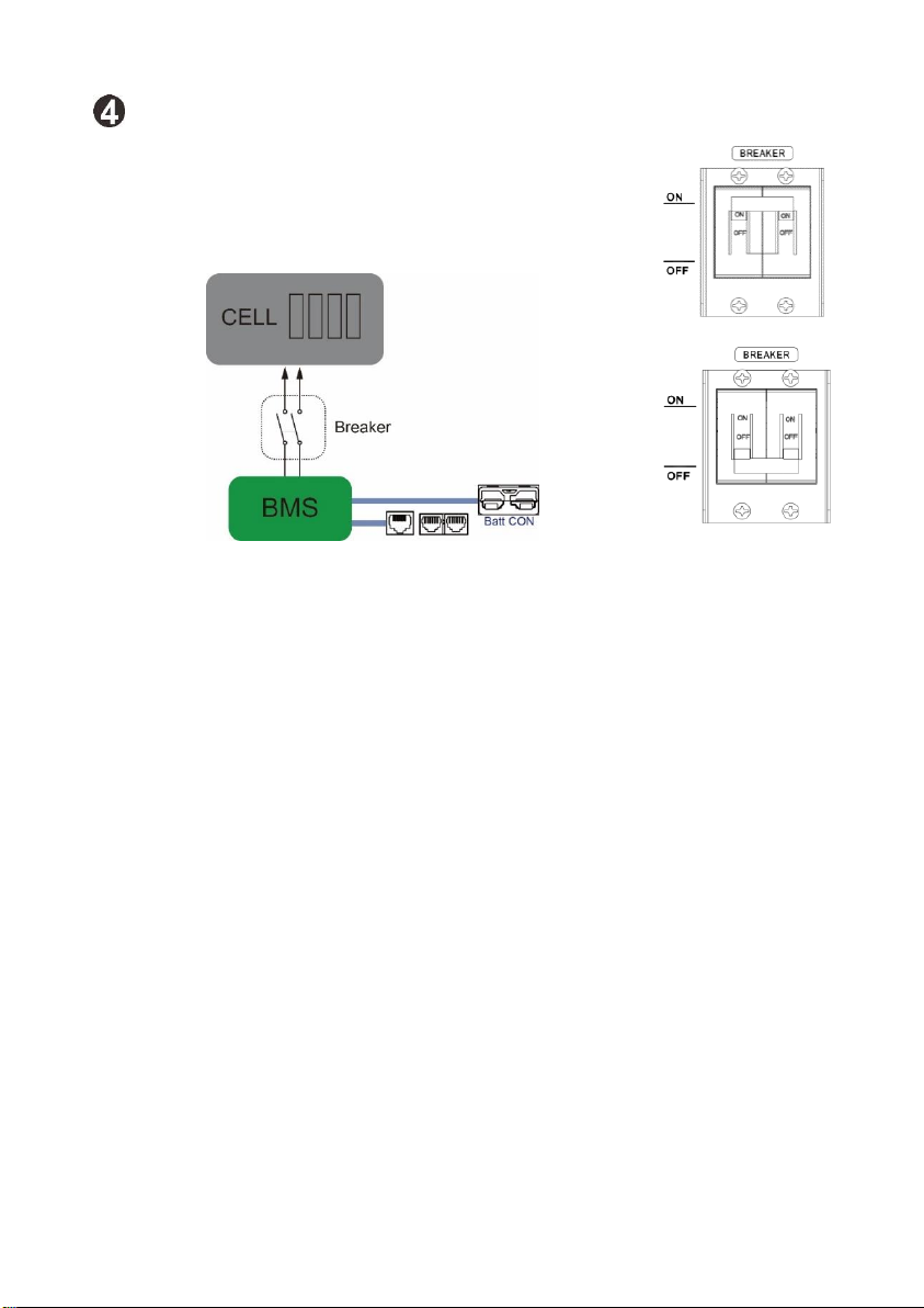
Both N1C.L4850EBM2U, N1C.L48100EBM3U are built-in smart BMS battery
management system, which can manage and monitor cells’information
including voltage, temperature, current, etc. Moreover, BMS can balance
cells charging and discharging to extend cycle life. These two battery
modules can be used alone or in parallel, to expand capacity for different
requirements.
2.1 Features
Non-Toxic, non-polluting, and friendly to the environment.
LiFeO4 cell material, safety performance, and long cycle life.
Smart BMS protection functions: over-discharge, high temperature,
over-charge, over-current.
Flexible configuration, multiple battery modules can be operating in
parallel for expanding capacity and power.
Working temperature range is from 0°C to 50°C with excellent
discharge performance and cycle life.
Small size and lightweight: up to the standard of the 19-inch embedded
designed module are comfortable for installation and maintenance.

4
2.2 Package Contents
The packaging is recyclable, save it for reuse or dispose of it properly
Module(x1) Manual(x1) Quick Installation Guide(x1)
Ear Kit(x1) Screws(x8) Battery cable(x1) RJ45 cable (x1) RJ11 cable(x1)
Signal cable (x1) *Optional: Battery cable (x 1) Rail Slide Kit
*Can be purchased separately.
2.3 Dimensions
N1C.L4850EBM2U N1C.L48100EBM3U

5
2.4 Specifications
Model
N1C.L4850EBM2U
N1C.L48100EBM3U
Nominal Voltage
48 VDC
48 VDC
Total Capacity
50 Ah
100 Ah
Nominal Capacity (Wh)
2400 Wh
4800 Wh
Full Charge Voltage (FC)
52.5 V
52.5 V
Full Discharge Voltage
(FD)
34.5 V
34.5 V
Max. Continuous
DischargeCurrent
75 A
75 A
Max. Peak
DischargeCurrent
100 A
100 A
Max. Current on
BatteryConnector
75A
75A
Protection
BMS, Breaker
Max. Charge Voltage
52.5 V ± 0.1 V
Max. Charge Current
50 A (1C)
Standard Charge Method
0.2C CC (Constant Current) chare to FC,CV
(Constant Voltage) charge till chargecurrent
decline to <0.05C
Inner Resistance
< 20m ohm
Storage Temperature
-20℃~25℃<18 months Max. 80%RH
25℃~45℃<3 months Max. 80%RH
45℃~60℃<1 month Max. 80%RH
20°C± 5 °C is the recommended storagetemperature
Dimension (D x W x H)
616 x 488 x 86 mm
24.25 x 19.21 x 3.39 in
616 x 488 x 129 mm
24.25 x 19.21 x 5.08 in
Net Weight
28.1 kg
61.95 lb
48.1 kg
106.04 lb
Operation Temperature
Charge : 0ºC ~ 50 ºC
Discharge : 0ºC ~ 50 ºC
Communication
RS485 (RJ45), extension port (RJ11)
Certifications
UL1973, UN38.3, IEC 62619
Design Life
>10 years @ 25 ºC
Lifecycle
> 2000 @ 25 ºC

6
2.5 Product Indicator & Setting
N1C.L4850EBM2U front and rear panel
N1C.L48100EBM3U front and rear panel

7
Manual power on/off button - to wake up or shut down the battery
module.
If battery module is off, press and hold the button for
approximately 5 seconds to turn on the module.
If battery module is working, press and hold the button for
approximately 3 seconds to shut down the module.
Battery Status LEDs - Indicates battery module status. Please refer to
the LED indicator table for the details.
Battery Level LEDs - Indicates battery level. Please refer to the LED
indicator table for the details.
LED Indicator:
Battery Status
Battery Status LEDs
Battery Level LEDs
Status
SOC
RUN
ALARM
LED1
LED2
LED3
LED4
Normal
Mode
Charging
0%~25%
ON
OFF
Flash
OFF
OFF
OFF
26%~50%
ON
OFF
ON
Flash
OFF
OFF
51%~75%
ON
OFF
ON
ON
Flash
OFF
76%~100%
ON
OFF
ON
ON
ON
Flash
Discharging
0%~25%
ON
OFF
ON
OFF
OFF
OFF
26%~50%
ON
OFF
ON
ON
OFF
OFF
51%~75%
ON
OFF
ON
ON
ON
OFF
76%~100%
ON
OFF
ON
ON
ON
ON
Alarm
mode
Warning
-
OFF
Flash
-
Fault
-
OFF
On
-
Power Off
-
OFF
OFF
OFF
OFF
OFF
OFF

8
Breaker
Turn the breaker ON: Connect cells to BMS
Turn the breaker ON: Shut down energy between
Cells and BMS

9
External Battery Connector
(1). CON1 & CON2 in parallel.
(2). “Positive” marked in ”+”,
“Negative” marked in “-”
COM Port
Connector type: RJ45
Function: communication between battery
module and power module.
Pin Definition
PIN
Definition
1
RS485B
2
RS485A
3
NC2
4
RS485B
5
RS485A
6
PresentA
7
PresentB
8
NC1
Extension Port
Connector type: RJ11
Function:
1. For battery capacity extension by parallel
2. BMS signal transmission
Pin Definition

10
PIN
Definition
1
CANH
2
CANL
3
PresentA
4
PresentB
5
NC
6
NC
ID Switch
ID Switch indicates the unique ID code for each battery module.
It's required to assign a unique ID to each battery module for
normal operation.
We can set up the ID code for each battery module by rotating
the PIN number on the ID switch. From number 0 to 9, the
number can be random; no particular order.
If more than one battery module in the parallel system, the
battery pack connected to the power module is the Master battery
and the ID code should be set as 0. The ID code of the remaining
battery module MUST be unique. Not the same number for 2
battery modules in parallel system.
Maximum 10 battery modules can be operated in parallel.
PIN
Definition
0
0x5B4
1
0x5B3
2
0x5B2
3
0x5B1
4
0x5B0
5
0x5AF
6
0x5AE
7
0x5AD
8
0x5AC
9
0x5AB

11
3. Safe handling of lithium batteries guide
3.1 Product handling guidelines
3.2 Explanation of symbol

12
4. Installation
4.1 Installation Environment
Make sure that the installation environment meets the following conditions:
The area is completely waterproof.
The floor is flat and level.
There are no flammable or explosive materials nearby.
The ambient temperature is within the range of 0~50°C.
The temperature and humidity are maintained at a constant level.
There is minimal dust and dirt in the area.
Caution:
If the ambient temperature is out of the operating range, the battery module will
stop operate to protect itself. The optimal temperature range for the battery module
to operate is 0°C to 50°C. Frequent exposure to harsh temperatures may deteriorate
the performance and shorten the life cycle of the battery module.

13
4.2 Installation
Before installation, please pay attention to the following actions to avoid damage.
Caution:
If there is breaker installed on the battery cable between power module and battery
module, turn on this breaker before battery module is powered on. Otherwise, it may
cause surge current.
Power Module
Turn "ON" the breaker before battery module is powered on.
Battery Module
Breaker

14
Single Battery Module Connection
1. Insert the supplied signal cable into the extension port ( P1 or P2 ).
*It's requested to connect to the battery module for normal operation.
2. Use supplied battery cable to connect to power module via CON1 or CON2.
3. Insert the supplied RJ45 cable into the COM port on the battery module. The
other end connects to BMS communication port on the power module.
Power Module
❸
❷
Battery module
❶
*Insert signal cable into the extension port or .
4. Turn the breaker switch “ON". Now, the battery module is ready for DC output.
5. Press manual ON/OFF button for 5 secs, the battery module will start up.
*If the manual button cannot be approached, just simply turn on the power
module. The battery module will be automatically turned on.

15
Multiple Battery Modules in Parallel
1. Insert the supplied signal cable into the extension port ( P1 or P2 ) on the
Master battery module #1.
*It's requested to connect to the battery module for normal operation.
2. Use supplied battery cable to connect to power module via CON1 or CON2.
3. Insert the supplied RJ45 cable into the COM port on the battery module. The
other end connects to BMS communication port on the power module.
Power module conneting with multiple battery modules for capacity extension:
Battery Module 1
Battery Module 2
Battery Module 3
Battery Module 10
*The battery module connected to the RS485 port on power module will be master
battery module. Be sure to set ID of master battery as “0”.
Master
❷
❸
❶
❹

16
4. Insert supplied RJ11 cable to connect the extension port of the Master battery
module #1. The other end connects to the extension port of the battery
module #2.
5. Use supplied battery cable to connect to the Master battery module #1 and
battery module #2.
6. If more battery modules to connect the system, repeat step 4 and 5 to connect
more battery modules.
7. After connecting all battery modules, turn the breaker switch “ON" of each
connected battery module. Now, the battery modules are ready for DC output.
8. Press manual ON/OFF button of each connected battery module for 5 secs. All
battery modules will start up.
*If the manual button cannot be approached, just simply turn on the power
module. The battery module will be automatically turned on.

17
5. Start-Up/Shut-Off the Battery Module
5.1 Start up the battery module
1. When battery module is in the shutdow mode, press manual
ON/OFF button for 5 secs.
2. Or, simply turn on the the power module and connect battery module to
operating power module. The battery module will be automatically turned on.
5.2 Shut-off the battery module
1. When battery module is in the operating mode, press manual ON/OFF button
for 5 secs.
2. Or, if battery module is not operated (charge or discharge) for 10 hours, the
battery module will automatically shut off.
3. Or, the battery module has no connection to the system (power module).
After operates without any connection with the COM Port (RS-485) for 24
hours, the battery will shut-off automately.
4. Or, the battery module is removed from the power module after 24 hours, the
battery will shut-off automately.
5. Or, when the cell voltage is lower than 2.3V/Cell for 10 minutes, the battery
module will shut-off.

18
6. Trouble Shooting
Use the table below to solve minor installation and operation problems.
Symptom
Possible cause
Remedy
Battery cannot
discharge.
Same ID code set in
multiple battery packs.
Re-set each battery with
different ID codes.
Protection against under-
voltage.
Charge battery.
Protection against over-
temperature or under-
temperature (cell
temperature is lower than
-20°C or higher than
80°C).
Regulate cell temperature
in the range of -20°C to
60°C for discharge.
Protection against over
current
Remove some non-critical
load and charge battery.
Battery output is short
circuit
Relieve short circuit and
charge battery
System failure detected
Shut down system and
call maintenance service
In parallel battery packs,
CAN communication lost
and “parallel imbalance”
occur on slave battery.
Ensure communication
wires are all correctly
connected well.
Battery cannot
charge.
Protection against over
current.
Ensure power shelf setting
is not over 1C for battery.
Protection against over-
temperature or under-
temperature (cell
temperature is lower than
0°C or higher than 60°C)
Regulate cell temperature
in the range of 0°C to
50°C for charge
System failure detected
Shut down system and
call maintenance service.
Communication
failure is detected.
Communication cable
Check if communication
cable is firmly connected.
Communication address
conflict
Check the parallel
batteries address setting
and correct them.
System failure detected
Shut down system and
call maintenance service.
This manual suits for next models
2
Table of contents