Nabco Acusensor M User manual

1 of 28
Acusensor M Installaon Manual
P/N C-00187 Rev 8-25-17
Nabco Entrances Inc. S82 W18717 Gemini Drive Muskego, Wisconsin 53150
Phone: (877) 622-2694 Fax: (888) 679-3319 www.nabcoentrances.com
NABCO hours of Operaon: Monday to Friday 8:00 a.m.- 4:30 p.m. (Central Time)
• Turn OFF all power to the Automatic Door if a Safety System is not working.
• Instruct the Owner to keep all power turned OFF until corrective action can be achieved
by a NABCO trained technician. Failure to follow these practices may result in serious
consequences.
• NEVER leave a Door operating without all Safety detection systems operational.
WARNING
Table of Contents
............................................................. 3
Secon 1.1: Warning Labels ...................................................................3
Secon 1.2: General Safety Recommendaons ...................................................3
.............................................................. 4
Secon 2.1: To the Installer ....................................................................4
Secon 2.2: Objecve ........................................................................4
..................................................... 4
.......................................... 5
.......................................... 8
Secon 5.1: Secure Sensor to Header ...........................................................8
Secon 5.2: Install the Angled Spacer (Sold Separately) ............................................8
............................................. 9
Secon 6.1: Wire Swing Door with Monitoring (Opus Control) .......................................9
Secon 6.2: Wire Fold Door with Monitoring (Opus Control) .......................................10
Secon 6.3: Wire Slide Door with Monitoring (U30 Control) ........................................10
...............................................
Secon 7.1: Operaon Mode (Switches 1 and 2) .................................................12
Secon 7.2: Output Logic (Switch 3) ...........................................................12
Secon 7.3: Input Logic (Switch 4) .............................................................13
Secon 7.4: Width Seng (Switches 5 thru 8) ...................................................13

2 of 28
Acusensor M Installaon Manual www.NabcoEntrances.com
P/N C-00187 Rev 8-25-17
..............................................
Secon 8.1: Depth Seng (Switches 9 thru 11) ..................................................15
Secon 8.2: Learn Time (Switches 12 and 13) ....................................................17
Secon 8.3: An-Noise (Switch 14) ............................................................18
Secon 8.4: An-Environment (Switches 15 and 16) ..............................................18
Secon 8.5: Sensivity (Switches 17 and 18) ....................................................18
Secon 8.6: IP Mode (Switches 19 and 20) ......................................................19
....................................................
...................................................
.......................................................

3 of 28
www.NabcoEntrances.com AcusensorMInstallaonManual
Rev 8-25-17 P/N C-00187
Warning labels are universal and used to alert an individual of potential harm to one’s self or to others. The following warning
Indicates potentially dangerous situations. Danger is used when there is a hazardous situation
where there is a high probability of severe injury or death. It should not be considered for
property damage unless personal injury risk is present.
Indicates a hazardous situation which has some probability of severe injury. It should not be
considered for property damage unless personal injury risk is present.
Indicates a hazardous situation which may result in a minor injury.Caution should not be used
when there is a possibility of serious injury. Caution should not be considered for property
damage accidents unless a personal injury risk is present.
Do not place nger or uninsulated tools inside the electrical controller. Touching wires or
other parts inside the enclosure may cause electrical shock, serious injury or death.
Disconnect power at the fused disconnect during all electrical or mechanical service. When
uncertain whether power supply is disconnected, always verify using a voltmeter.
If the door appears broken or does not seem to work correctly, it should be immediately
removed from service until repairs can be carried out or a qualied service technician is
contacted for corrective action.
DANGER
WARNING
CAUTION
DANGER
WARNING
CAUTION

4 of 28
Acusensor M Installaon Manual www.NabcoEntrances.com
P/N C-00187 Rev 8-25-17
The purpose of this manual is to familiarize the installer and purchaser with the proper installaon and operaon of the Acusensor
M. It is essenal that this equipment be properly installed and operaonal before the door is used by the public. It is the installer’s
responsibility to inspect the operaon of the entrance system to be sure it complies with any applicable standards. In the United
States, ANSI Standard 156.10 (Full Energy) covers these types of doors. Other local standards or codes may apply. Use them in
addion to the ANSI standard.
Instruct the building owners and operator on the essenals of the operaon of the door and this device. The owner should follow
these instrucons to determine whether the door is operang properly and should immediately call for service if there is any
malfuncon. All installaon changes and adjustments must be made by qualied, NABCO trained technicians.
If aer troubleshoong a problem, a sasfactory soluon cannot be achieved, please call Nabco Entrances at 1-877-622-2694
between 8 am – 4:30 pm Central me for addional assistance.
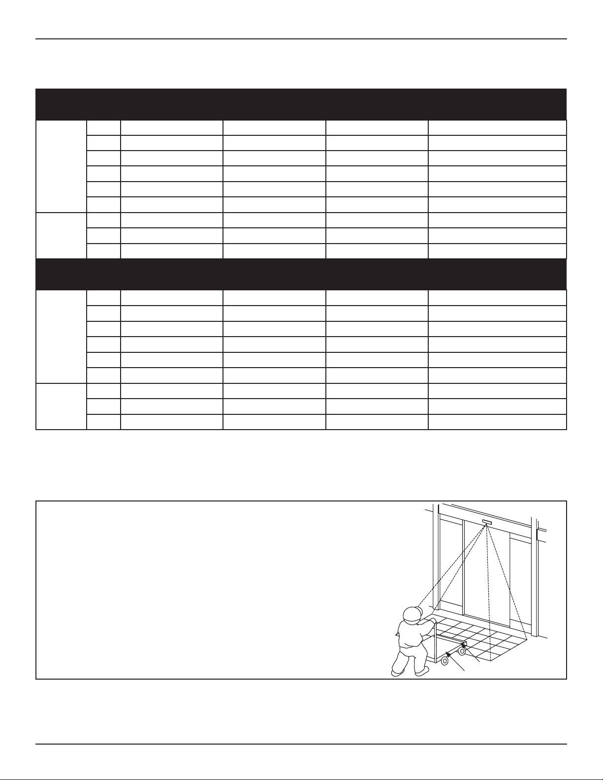
Acusensor M is mounted on the Header Cover for all Slide Door Units, Swing Door Units, and Fold Door Units. The Acusensor M is
used to detect changes of mulple near-infrared rays that beam from the Sensor down to various points on the oor. The Acusensor
M can detect a moving pedestrian or object, or a staonary pedestrian or object. Upon Presence Detecon, the Acusensor M
outputs a detecon signal to Control. The Control automacally sends a signal to the Motor/Operator, the Motor/Operator opens
the automac door.
The Acusensor M was developed based on the concept of safety, comfort, reliability and mulpurpose.
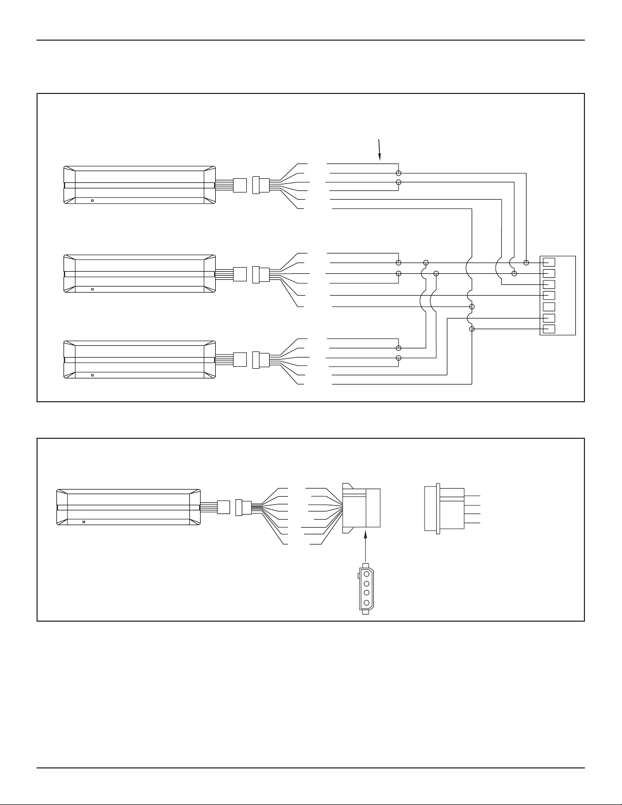
All wiring must conform to standard wiring practices and be in accordance with national and
local electrical codes.
Note: It is recommended for the Installer to use an Electrical Conduit to house all incoming 120 VAC wires.
Table 1
Specification Description
Sensing System Acve reecve near infrared system (Moon/Presence)
Life Expectancy (5) years. LED illuminates a:
►White light during Learning that blinks twice every (5) seconds
►Green light during Normal Operation that blinks twice every (5) seconds
• Flashing LEDs do not indicate that the Sensor is failing.
• Flashing LEDs indicate that the Sensor has been in use for a period of me, and replacement
is recommended. This is done to ensure connued safe operaon of the door.
Applicable door Sliding door/Swing door/Folding door
Detecon Area ►Without angled spacer
• Width 114”(2.9m) x Depth 71”(1.8m) (at mounng height 87”(2.2m))
►With angled spacer (sold separately)
• Width 114”(2.9m) x Depth 78”(2.0m) (at mounng height 87”(2.2m))
The width and depth of a Detecon Area may vary. For details, please refer to Table 3-1. This is
typically the result of:
►A variance in mounting height.
►Normal manufacturing and component tolerances.
►
►Use of spacers for mounting.
Output Contacts Rang Non-polarized, No voltage, Semi-conductor relay output 30 VAC/50VDC, 0.1A (Resistance Load)
N.C. or N.C.
When Set to N.O. ►No Detection “Open”
►Detection “Closed”
►Power Failure “Open”
►Sensor Malfunction “Closed”
WARNINGWARNING

5 of 28
www.NabcoEntrances.com AcusensorMInstallaonManual
Rev 8-25-17 P/N C-00187
Specification Description
Mounng Height 78 inches to 118 inches (2.0m to 3.0m)
Weight Approximately 10 ounces (285g)
Color Black Cover or Silver Cover
Full Color LED ►Displays operating status
Angled Spacer The Angled Spacer is an opon that is sold separately. To do so, please call Customer Service at
1-888-679-3319.
►For Slide doors only
►For increased depth range.
Adjustable Detecon Area
►Depth
►Width
ECO Mode Closes door earlier for a pedestrians moving away from door.
Table 2 Electrical Wiring
Item Description
Input Voltage 12-24 Volts AC or DC
Power Consumpon 3VA or less @ 24VAC
80mA or less @ 24VDC
150mA or less @ 12VDC
Output ►
►Max. 100mA @ 30VAC/50VDC
Make sure total power consumption of all Sensors does not exceed the capability of the door control or power supply.
Exceeding the rated output may result in malfunction or breakdown.
The Sensor is used to detect changes of mulple near-infrared rays that beam from the Sensor down to various points on the oor.
These various points reect the near-infrared rays to form an grid in the shape of a square. To more acurately monitor a Presence
Detecon Area, the grid is broken into invisible rows (Depth), and columns (Width).
DN 1567
Mounng
Height
Row 1
Row 2
Row 3
Row 4
Row 5
Row 6
AB
CDEF

6 of 28
Acusensor M Installaon Manual www.NabcoEntrances.com
P/N C-00187 Rev 8-25-17
Table 3 Detection Area Size
Without Angled Spacer (Area Adjuster set at 0 degrees)
Mounting Height 78” (2.0m) 87” (2.2m) 98” (2.5m) 118” (3.0m)
Depth
A 4” (100mm) 4” (100mm) 5” (120mm) 6” (150mm)
B 15” (390mm) 17” (430mm) 19” (480mm) 23” (580mm)
C 26” (650mm) 28” (720mm) 32” (820mm) 39” (980mm)
D 38” (960mm) 41” (1,050mm) 47” (1,200mm) 57” (1,440mm)
E 51” (1,300mm) 56” (1,430mm) 64” (1,620mm) 77” (1,950mm)
F 63” (1,600mm) 72” (1,820mm) 82” (2,070mm) 98” (2,490mm)
Width
G 48” (1,220mm) 53” (1,350mm) 60” (1,530mm) 72” (1,840mm)
H 83” (2,100mm) 91” (2,320mm) 104” (2,630mm) 124” (3,160mm)
I 104” (2,640mm) 114” (2,900mm) 130” (3,300mm) 156” (3,960mm)
With Angled Spacer (Area Adjuster set at 0 degrees)
Mounting Height 78” (2.0m) 87” (2.2m) 98” (2.5m) 118” (3.0m)
Depth
A 4” (100mm) 4” (100mm) 5” (120mm) 6” (150mm)
B 15” (390mm) 17” (430mm) 19” (490mm) 23” (590mm)
C 26” (670mm) 29” (740mm) 33” (840mm) 40” (1.010mm)
D 38” (1000mm) 43” (1,100mm) 49” (1,250mm) 59” (1,500mm)
E 54” (1,370mm) 59” (1,510mm) 68” (1,720mm) 81” (2,060mm)
F 71” (1,790mm) 78” (1,970mm) 88” (2,240mm) 106” (2,680mm)
Width
G 48” (1,230mm) 53” (1,350mm) 61” (1,540mm) 79” (1,850mm)
H 83” (2,110mm) 91” (2,320mm) 104” (2,640mm) 125” (3,170mm)
I 104” (2,650mm) 114” (2,920mm) 131” (3,320mm) 157” (3,980mm)
Illustrated examples shown below, are meant to display some (not all) causes for malfuncon to occur within the Presence
Detecon Area.
Table 4 Common Causes for Malfunctions
The bed of a trolley:
XIs too low to the oor
XSurface of cart or trolley is not reecve enough to be detected. (Reecve
tape or sckers can help)
Refl ec ve S cker
Trolley BedDN 1568

7 of 28
www.NabcoEntrances.com AcusensorMInstallaonManual
Rev 8-25-17 P/N C-00187
Sensor is exposed to:
XSteam
XExhaust fume
XInsects
XHeavy rain
XHeavy snow
DN 1572
Pool of water located within Presence Detecon Area
DN 1571
An object placed within the Presence Detecon Area that may be moving within
the detecon area (like due to wind).
DN 1573
Mulple Sensors installed close to each other, or facing each other Within 197” (5m)
DN 1569
Presence Detecon Area is ooded with:
XStrong direct Sunlight
XSunlight reecng from oor (such as marble, or aluminum oors)
XStrong direct arcial light
XArcial light reecng from oor (such as marble, or aluminum oors)
XLighng xtures placed too close to the Sensor
DN 1570

8 of 28
Acusensor M Installaon Manual www.NabcoEntrances.com
P/N C-00187 Rev 8-25-17
Shut OFF the installation site, branch Circuit Breaker. Failure to do so may result in serious
personal or fatal injury. When uncertain whether power supply is disconnected, always verify
using a voltmeter.
All high voltage electrical connections must be made by licensed electricians according to
National and Local electrical codes/regulations.
Permanent wiring shall be employed as required by local codes.
Keep all Incoming 120 VAC wiring separate from low voltage wiring within Header. 120 VAC
Power wires must be routed (separate from other wiring) located near the top of inside Header.
1. Turn OFF power.
2. Remove Cover from Sensor.
3. Remove (2) #10 x 1/2 inch Phillips Panhead screws from the cradles.
DN 1574
#10 x 1/2”
Phillips Head
Screw
Sensor
Cover
Figure 1 XXXX
4. Line up the predrilled screw holes located on the Mounng Plate with predrilled screw holes on the Header Cover.
5. Secure the Sensor to the Header Cover with (2) #10 x 1/2 inch Phillips Panhead screws.
Predrilled
Screw Holes
Predrilled Screw Holes
Sensor
DN 1575
#10 x 1/2”
Panhead Screw
Figure 2 Recessed Track
Note: The Angled Spacer is an opon that is sold separately. To do so, please call Customer Service at 1-888-679-3319.
1. Turn OFF power.
2. Remove Cover from Sensor.
3. Seat the Sensor inside the Angled Spacer.
a. The at side of Angled Spacer must bu up against the Header Cover.
4. Align the predrilled screw holes located on the Mounng Plate with the predrilled screw holes located on the Angled Spacer.
5. Secure the Sensor to the Header Cover with (2) #10 x 5/8 inch Phillips Panhead screws (supplied with the Angled Sensor Kit.
a. Do not use (2) #10 x 1/2” Phillips Panhead screws that were supplied with the Acusensor M kit.
WARNING
WARNING
CAUTION
CAUTION

9 of 28
www.NabcoEntrances.com AcusensorMInstallaonManual
Rev 8-25-17 P/N C-00187
DN 1580
Figure 3 Install the Angled Sensor
DN 1578
7
6
54
321
10
98
11 12 13 14
ACUSENSOR M TO OPUS IN SWING DOOR WITH MONITORING
ACUSENSOR M
ACUSENSOR M
APROACH SIDE (ACTIVATION)
SWING SIDE (SAFETY)
RED
BLACK
BROWN
GREEN
V-00741
V-00741
ACUSENSOR M HARNESS
A-01292
ACUSENSOR M HARNESS
A-01292
YELLOW
GREY
RED
BLACK
BROWN
GREEN
YELLOW
GREY
P.N. A-00805
ON/OFF/HOLD-OPEN SWITCH
BLUE
WHITE
BLACK
RED
Off
Hold Open
On
Off

10 of 28
Acusensor M Installaon Manual www.NabcoEntrances.com
P/N C-00187 Rev 8-25-17
DN 1577
7
6
54
321
ACUSENSOR M
ACUSENSOR M
FOLD SIDE ACTIVATION
APROACH SIDE ACTIVATION
FOLD SIDE SAFETY
RED
BLACK
BROWN
GREEN
V-00741
V-00741
ACUSENSOR M
V-00741
ACUSENSOR M HARNESS
A-01292
1
2
3
1
2
4
1
2
6
To Terminal # on Opus Control
ACUSENSOR M HARNESS
A-01292
ACUSENSOR M HARNESS
A-01292
YELLOW
GREY
7
RED
BLACK
BROWN
GREEN
YELLOW
GREY
7
RED
BLACK
BROWN
GREEN
YELLOW
GREY
7
ACUSENSOR M TO OPUS IN FOLDING DOOR
WITH MONITORING
DN 1579
1
2
3
4
BROWN, GREY
RED, GREEN, BLUE
BLACK, WHITE
YELLOW
ACUSENSOR M
SWING SIDE (SAFETY)
V-00741
ACUSENSOR M HARNESS (WITH CONNECTOR)
P.N. A-01292
RED
BLACK (or Black with Red Stripe)
BROWN
YELLOW
ACUSENSOR M TO U-SERIES IN SLIDE DOOR WITH MONITORING
FROM U-SERIES CONTROL
BLACK
WHITE
BROWN
YELLOW
RED
GREY
GREEN
BLUE

11 of 28
www.NabcoEntrances.com AcusensorMInstallaonManual
Rev 8-25-17 P/N C-00187
1. Turn OFF power.
2. Li the resusable protecon ap located on the Le hand side of Acusensor M.
a. Underneath the ap are three groups of Switches.
DN 1559 Switches 1-8
Switches 9-16
Switches 17-20
Figure 4 Switch Settings
b. The backside of Flap shows a diagram for how to set switches 1 thru 8.
DN 1560
Operaon Mode Output
Logic
Input
Logic
Width (L) Width (R)
12 345678
# Normal #N.O. # High #6 #6
Doorway 2 N.C. Low 5 5
* Doorway 1 4 4
First Row Off 3 3
#Default Seng * Install Sensors on both sides of the Door
Operaon Mode Determines what part of the Presence Detecon Area (grid) is being monitored.
Output Logic Normally Open/Normally Closed
Input Logic Please refer to “Input Logic” Secon
Width (L) Adjusts width of Presence Detecon Area (grid) on the LeSide of Door independently
Width (R) Adjusts width of Presence Detecon Area (grid) on Right Side of Door independently
Figure 5 Switch Setting Diagram located under Flap

12 of 28
Acusensor M Installaon Manual www.NabcoEntrances.com
P/N C-00187 Rev 8-25-17
DN 1561
Presence Detecon Area
Row 1
Row 6
Note:
Row 1 is the Threshold Area
Figure 6 Presence Detection Area
Note: Labeled as Operaon Mode but is actually a Monitoring Operaon Mode.
Monitoring is an added layer of communicaon between the control and the sensor. The control will send a signal to the sensor. The
sensor performs a self-diagnosc test, then sends a signal back to the control conrming proper operaon.
The Monitoring Operaon Mode (set by dip switches 1 and 2) determines which rows of presence detecon are acve and which
are applied to the monitoring funcon. Acve rows are not the same as rows that are monitored. Rows can be acve (able to tell the
control to open the door) but not be applied to the Monitoring funcon.
Table 5 Standard Monitoring Operation Modes
Operation Mode
1 2 Door Type Presence Detection Area Monitor Description
Normal Slide Depth Row 1 and 2 Doorway monitoring is not applied for Depth Row 3 thru 6
Doorway 2 XSwing
XFold
Depth Row 1 thru 6 XDoorway monitoring works for all Depth Rows
XFold, and Swing doors only
Doorway 1 Slide Depth Row 2 and 3 XDoorway monitoring works for Depth Row 1
XDoorway monitoring does not work for Depth Row 2
thru 6
1st Row OFF Slide Depth Row 2 and 3 XDepth Row 1 becomes inacve
XDoorway monitoring is not applied for Depth Row 2
thru 6
Note: Ensure both the Acusensor M and the Control is set for N.O. or N.C.
When a presence is detected within a monitored area, the control automacally sends a pulse to Input Logic. Output Logic
automacally responds by opening the door.
Table 6 Output Status
Output Logic
3 Definition Stand-by Detecting Action Test Reply
(Good)
Test Reply
(Error)
Power OFF
N.O. Normally
Open
Circuit closes
Door opens
N.C. Normally
Closed
Circuit opens
Door opens

13 of 28
www.NabcoEntrances.com AcusensorMInstallaonManual
Rev 8-25-17 P/N C-00187
In the event a Self Diagnosc Error occurs, the door will not open. Instead the Sensor LED will illuminate a blinking Red Light (1Hz)
indicang an Error.
Note: Ensure both the Acusensor M and the Control is set for N.O. or N.C.
Table 7 High Setting vs Low Setting
Input Logic
4 Description
High +input Connects to +voltage
- input Connects to Output, regardless of Switch 4 Seng.
XU30 FUNCTION (6) seng should be No
XOpus seng should be “Sensor Monitoring N.O. (Normally Open)
Low +input Connects to +voltage
- input Connects to Output, regardless of Switch 4 Seng.
XU30 FUNCTION (6) seng should be “Yes”.
XOpus seng should be “Sensor Monitoring N.C. (Normally Closed)
Note: On swing and fold doors, set width paern as narrow as needed to avoid detecon of the door in the open posion.
Table 8 Presence Detection Area
Width (L) Width Area Diagram Width (R)
5 6 = Acve Area Le Side = Inacve Area = Acve Area Right Side 7 8
6 6
5 5
4 4
3 3

14 of 28
Acusensor M Installaon Manual www.NabcoEntrances.com
P/N C-00187 Rev 8-25-17
1. Turn OFF power.
2. Li the reusable protecon ap located on the Le hand side of Acusensor M.
a. Underneath the ap are three groups of Switches.
DN 1562
Depth Learn Time Anti-Noise Anti-Environment Sensitivity IP Mode
91011910 11 12 13 14 15 16 17 18 19 20
6 2 30s Normal Normal H A
5 5-6eco 15s Special Anti-Vibration M B
4 4-6eco 60s Anti-Snow I L C
3 AreaCheck 300s Anti-Snow II SH D
Switches 1-8
Switches 9-16
Switches 17-20
Figure 7 Switch Settings
3. Go to the middle of the Acusensor M to locate a diagram for how to set switches 9 thru 20.
DN 1563
Depth Learn Time Anti-Noise Anti-Environment Sensitivity IP Mode
91011910 11 12 13 14 15 16 17 18 19 20
#6 2 #30s #Normal #Normal #H #A
5 5-6eco 15s Special Anti-Vibration M B
4 4-6eco 60s Anti-Snow I L C
3 Area
Check
300s Anti-Snow II SH D
#Default Seng IP Mode Interference Protecon
Depth Adjusts depth of Presence Detection Area (grid)
Learn Time The amount of time it takes for the sensor to learn the area, or relearn if a normally stationary
object is moved. ANSI requires minimum 30sec.
Anti-Noise Helps prevent false detection caused by electrical noise or nearby light sources.
Anti-Environment Helps prevent false detection caused by vibration, insects, snow.
Sensitivity Adjust signal strength for detecting moving pedestrians or objects. Example: For slow moving
pedestrians or objects, sensitivity option should be on Medium or High.
IP Mode Helps prevent interference caused by sensors near each other.
Figure 8 Switch Setting Diagram

15 of 28
www.NabcoEntrances.com AcusensorMInstallaonManual
Rev 8-25-17 P/N C-00187
DN 1561
Presence Detecon Area
Row 1
Row 6
Note:
Row 1 is the Threshold Area
Figure 9 Presence Detection Area
Table 9
Depth
910 11 Detection Area Diagram 910 11 Detection Area Diagram
62
5 5-6 ECO
44-6 ECO
3*Area
Check
Operaon Mode Normal This row is acve, but not applied to the monitoring funcon.
Doorway 1 This row is acve, and is applied to the monitoring funcon.
1st Row OFF Inacve
ECO Mode XDireconal presence detecon. For detailed informaon please refer to Subsecon 6.a.a.
XSame Depth Rows are Acve.
No Monitoring XThese rows are acve, but not applied to the monitoring funcon.
XDepth Rows Acve.
Inacve Depth Rows are not Acve.
*Used for adjusng detecon area depth and conrming test command input, during installaon only. For detailed informaon
please refer to Subsecon 6.a.b.

16 of 28
Acusensor M Installaon Manual www.NabcoEntrances.com
P/N C-00187 Rev 8-25-17
Table 10 Depth for Operation Mode: Doorway 2
Depth
910 11 Detection Area Diagram 910 11 Detection Area Diagram
62
5N/A ECO Mode does not work well with
Swing and Fold doors.
4N/A ECO Mode does not work well with
Swing and Fold doors.
3Area
Check
Operaon Mode XDoorway monitoring works
XDepth Rows are Acve
XDepth Rows will never be Acve
XIf Row 1 is Acve, mis-detecon will occur on
Swing Doors and Fold Doors
Inacve Depth Rows are not Acve.
If mounting height for Sensor is low, movement can easily be detected within multiple rows at
the same time. Because of this, the ECO Mode may not operate correctly.
Note: ECO Mode is an acronym for Ecological Friendly Mode, also known a Direconal Sensing.
Note: ECO Mode is not used for Doorway 2 operaon.
ECO Mode is a funcon that decides whether movement is coming toward the door, or away from door (direconal sensing). If the
Sensor decides movement is going away from door, the High or Low feature will determine how far the object gets before the door is
allowed to close.
Mode Depth Rows Description
Low 5 and 6 Output stops when and object is detected moving away through rows 5 to 6.
1 thru 4 Output maintains when and object is detected in rows 4 to 1.
High 4, 5, and 6 Output stops when and object is detected moving away through rows 4 to 6.
1 thru 3 Output maintains when and object is detected in rows 3 to 1.
Area Check Mode is used for adjusng the depth of a detecon area, and conrm test command input.
An unique LED color is assigned to each Depth Row (1 thru 6). When the installer selects a Depth Row, the Sensor will illuminate each
assigned LED color.
If mulple Depth Rows are detected at the same me the Sensor’s LED will illuminate the color assigned to the Depth Row closest to
the face of Door.
CAUTION

17 of 28
www.NabcoEntrances.com AcusensorMInstallaonManual
Rev 8-25-17 P/N C-00187
Table 11 Assigned LED Colors
Row LED
1Red When Operaon Mode is set to (Normal) or (Doorway 2)
No Light When Operaon Mode is set to (Doorway 1) or (1st Row)
2Pale Blue
3Yellow
4Blue
5 Green
6 Purple
While in Area Check Mode, and every me the door opens, the Control will send a Test Command Input Signal to the Sensor. Before
the door starts to open, the Sensor LED will illuminate a blinking White light (4) mes (10Hz), indicang communicaon between the
Control and Sensor is normal.
While in Area Check Mode, the ECO Mode will become inacve, and Learn Time becomes 5 seconds.
Table 12 LED Operating Status
Sensor Status LED Sensor Operating Order
Recognized Test Command Input White Light blinks (4) mes 1
Detected Depth Row 1 thru 6 Assigned LED color 2
Stand-by No Light 3
During normal operaon, when a Depth Row is in Detecon, the Sensor’s LED will illuminate an assigned color.
If mulple Depth Rows are detected at the same me the Sensor’s LED will illuminate the color assigned to the Depth Row closest to
the face of Door.
Table 13 Assigned LED Colors
Operation Mode Depth Row 1 Depth Row 2 Depth Row 3 Depth Row 4 Depth Row 5 Depth Row 6
Normal RED Orange
Doorway I Purple Red Orange
Doorway II Red
1st Row OFF N/A Red Orange
In the event a moving pedestrian decidedly stands still within the Presence Detection Area for
a time longer than the “Learn Time”, the door may close and cause some probability of severe
injury or entrapment.
After Power is turned ON, do not enter the Presence Detection Area for (1) minute.
Learn Time is when the Sensor learns that a staonary object is part of the area, and learns to ignore that object in order for the door
to close. Learn Time diers due to the Switch Seng for Operaon Mode and Switch Seng for Depth Row.
Table 14 Learn Time
Operation Mode Row 1 Row 2 Row 3 Row 4 Row 5 Row 6
Normal Set: 15s, 30s, 60s, or 300s 5 seconds (xed)
Doorway 1 Set: 15s, 30s, 60s, or 300s 5 seconds (xed)
Doorway 2 Set: 15s, 30s, 60s, or 300s
1st Row OFF Inacve Set: 15s, 30s, 60s, or 300s 5 seconds (xed)
WARNING
WARNING

18 of 28
Acusensor M Installaon Manual www.NabcoEntrances.com
P/N C-00187 Rev 8-25-17
Note: An Noise helps prevent false detecon caused by electrical noise or nearby light sources.
Table 15 Anti-Noise
Anti-Noise
14 Description
Normal An Noise is OFF.
Special Use when a malfuncon occurs due to a lighng xture, or an electro magnec noise.
Table 16 Anti-Environment
Anti-Environment
15 16 Vibration * Mirror Snow Insect Note
Normal Inacve Inacve Inacve Inacve N/A
An-
Vibraon
Acve Inacve Inacve Inacve Use when Sensor malfuncons due to
door vibraon during operaon
An-Snow I Inacve Inacve Acve Acve Response me may slow down
An-Snow II Acve Acve * Acve ** Acve Select if no improvement is seen using
An-Vibraon and/or An-Snow I
*Response me may slow down
** Detecon Area narrows down
*Mirror is when Sensors are facing each other at a close distance.
Note: The Sensivity Mode may be acvated for reasons such as color/material of the oor or clothes.
Table 17 Sensitivity
Sensitivity
17 18 Mounting Height
H
(High)
X98” thru 118” (2.5m thru 3.0m)
XRecommended Switch Seng for above mounng height
M
(Medium)
X79” thru 98” (2.0m thru 2.5m)
XRecommended Switch Seng for above mounng height
L
(Low)
X79” thru 98” (2.0m thru 2.5m)
XUse if sensivity is too HIGH with Switch Seng (M)

19 of 28
www.NabcoEntrances.com AcusensorMInstallaonManual
Rev 8-25-17 P/N C-00187
Sensitivity
17 18 Mounting Height
SH
(Super High)
X98” thru 118” (2.5m thru 3.0m)
XUse if sensivity is too LOW with Switch Seng (H)
IP Mode is ulized when Sensors are placed within the same Area and/or when Sensors are facing each other. This is true for mulple
Acusensor M Sensors and/or older versions of the Acusensor, Acuvision, and/or Acumoon sensors.
To prevent Sensor Malfuncon, the IP Mode Seng must be dierent from that on each other sensor.
Table 18 IP Mode
IP Mode
19 20 Description
A Default for the Acusensor M
B Suggested IP Mode for 2nd Sensor
C Suggested IP Mode for 3rd Sensor
D Suggested IP Mode for 4th Sensor
The Area Adjuster is a Phillips Head screw that the installer turns to angle the Sensor:
XCounter Clockwise to adjust the Detection Area Pattern farther out.
XClockwise to adjust the Detection Area Pattern farther in.
An Angled Spacer (sold separately) can be used to provide a Presence Detecon Area outside of normal Depth.
1. Turn OFF power.
2. Go to Area Adjuster located on the Right hand side of Acusensor M.
DN 1565
Depth Learn Time Anti-Noise Anti-Environment Sensitivity IP Mode
91011910 11 12 13 14 15 16 17 18 19 20
6 2 30s Normal Normal H A
5 5-6eco 15s Special Anti-Vibration M B
4 4-6eco 60s Anti-Snow I L C
3 Area Check 300s Anti-Snow II SH D Area Adjuster
0
-10
Degree Indicator Charts
Degree Indicator
Area Adjuster
Figure 10 Area Adjuster

20 of 28
Acusensor M Installaon Manual www.NabcoEntrances.com
P/N C-00187 Rev 8-25-17
3. Turn the Area Adjuster unl the preferred Depth is achieved.
a. One half turn of the Area Adjuster:
XWithout an Angled Spacer is almost equivalent to (1) degree.
(1) degree = 1.57 inches (40mm) if the Sensor mounting height is 87 inches (2.2m)
XAdding the Angled spacer (sold separately) adds an additional 5 degrees.
b. As the phillips head screw is turned, the Degree Indicator Lever will move from (0 to -10 degrees).
DN 1566
# 0 degree
0 degree
-10 degree Minus
Direcon
-5 degree -10 degree
# = Default
Without
Angled Spacer
With
Angled Spacer
1. Flip Switches 9, 10, and 11 UP.
2. Turn ON Power. Turn the Area Adjuster unl Depth Row (1) can be detected within (5) inches from the face of Door.
a. To do so, walk within the presence detecon area unl the LED illuminates a Red light.
b. The Red light indicates that Depth Row (1) is detecng.
1. Flip Switches 9, 10, and 11 UP.
2. Turn ON Power. Locate the center of Depth Row (1 and 2).
a.
Turn the Area Adjuster until Depth Row (2) can be detected within (5) inches from face of Door.
a. Depth Row (2) should not become part of the Threshold.
XDetection must occur to within (5) inches of the face of the door.
XThe pattern needs to be moved out if the door itself is being detected.
XThe pattern needs to be moved in if there is a loss of detection at any point greater that (5) inches from the face
of the door.
Table of contents
Other Nabco Accessories manuals
Popular Accessories manuals by other brands

Tellur
Tellur Ultra Pro PD903 user manual

Festo
Festo SPAU Translation of the original instructions

Julabo
Julabo SC 5000a operating manual

Motorola
Motorola C370 Series instructions

Audioaccess
Audioaccess DBM21 Software Programming and Hardware Connecting Guide

Craftsman
Craftsman 316.792420 Operator's manual