Nabco Gyro Tech Acuvision User manual

S82 W18717 Gemini Drive
PO Box 906
Muskego, WI 53150
Phone: (877) 622-2694
Fax: (888) 679-3319
www.NabcoEntrances.com
P/N 15-10848-01
Revision 05-11-10
WARNING
Do not install, operate or service this product unless you have read and understood the Safety Practices,
Warnings, Installation and Operating Instructions contained in this manual. Failure to do so may result in
property damage or bodily injury.
Acuvision
Instruction Manual
WARNING
Turn OFF all power to the Automatic Door if a Safety System is not working.
Instruct the Owner to keep all power turned OFF until corrective action can be achieved by a NABCO
trained technician. Failure to follow these practices may result in serious consequences.
NEVER leave a Door operating without all Safety detection systems operational.

Page 2 www.NabcoEntrances.com 05-11-10
Acuvision Instruction Manual
Contents
A. Overview.................................................................................................................................................... 3
B. Specifications ............................................................................................................................................ 4
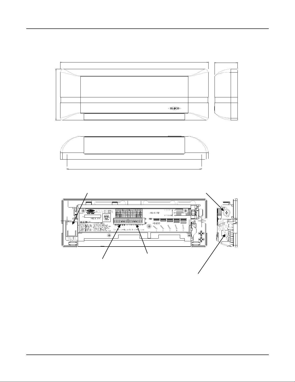
C. Appearance and Dimensions .................................................................................................................... 5
D. Installation and Adjustments
D.1 Installation .................................................................................................................................... 6
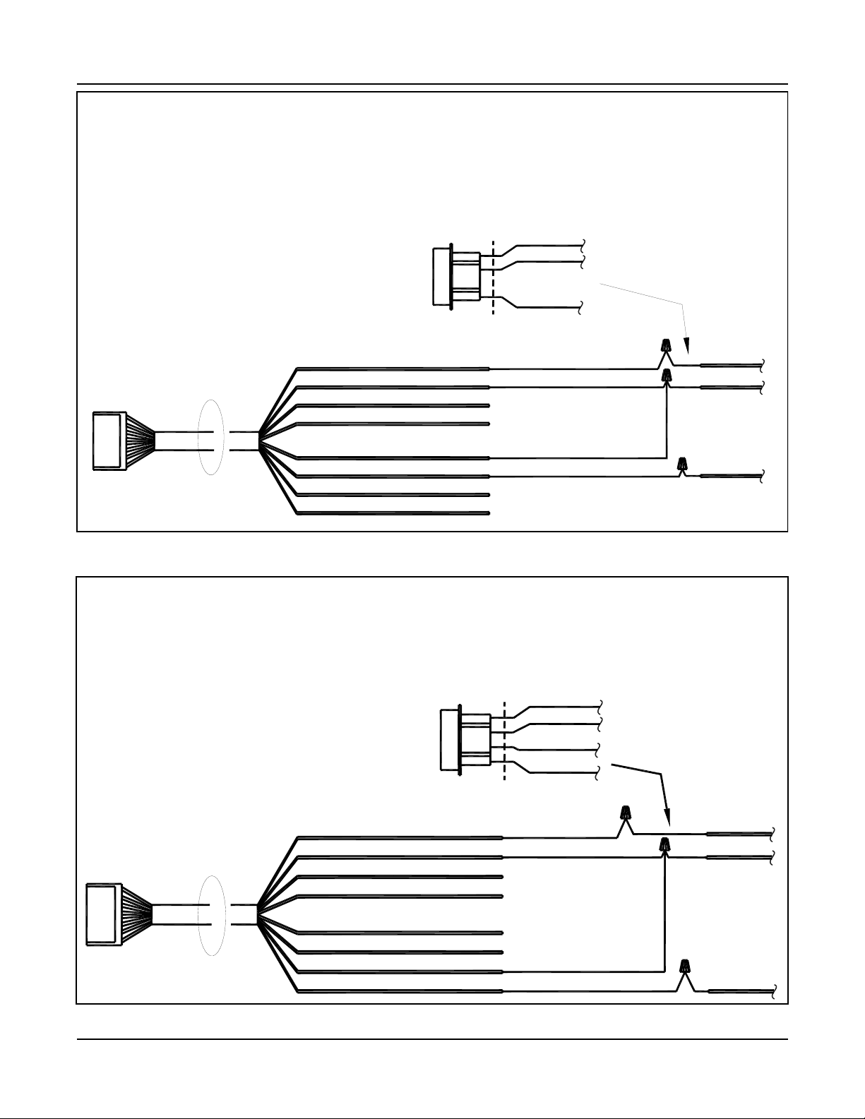
D.2 Wiring ........................................................................................................................................... 7
D.2.1 General Wiring Information ......................................................................................... 7
D.2.2 Wiring - Sliding Door with U Series Control ................................................................ 8
D.2.3 Wiring - Non-swing side of swing dr. or non-fold side of fold dr. w/ U Series Control 8
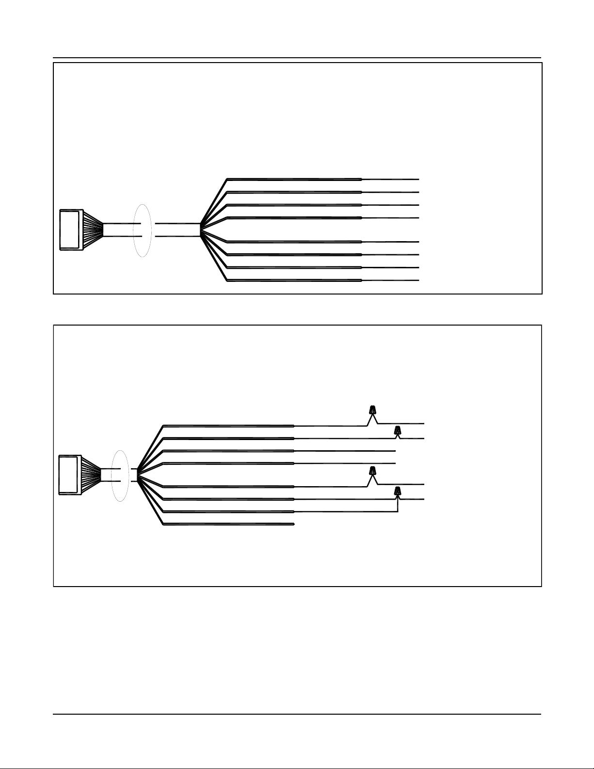
D.2.4 Wiring - Non-swing side of swing door with Magnum Control .................................... 9
D.2.5 Wiring - Swing Side of Swing Doors w/Analog Control................................................ 9
D.2.6 Wiring - Swing Side of Swing/Folding Door w/Microprocessor Control ..................... 10
D.2.7 Wiring - Swing Side of Swing Door w/Magnum Control............................................. 10
D.3 Turning ON the power ................................................................................................................ 11
D.4 Customized Settings
D.4.1) Setting up for depth coverage................................................................................... 11
D.4.2) Non-detection zone ................................................................................................... 12
D.4.3) Minute adjustment of depth coverage....................................................................... 13
D.4.4) Adjusting for Width Coverage ................................................................................... 13
D.4.5) Setting Width coverage ............................................................................................. 14
D.4.6) Operation Mode Set Up
D.4.6.1) Mutual Interference Prevention Setting ............................................. 15
D.4.6.2) Activation Signal Setting..................................................................... 16
D.4.6.3) Sensitivity setting................................................................................ 16
D.4.6.4) Standstill memory time ....................................................................... 16
D.4.6.5) Door Mode setting ............................................................................. 17
D.4.6.6) Output Time Delay.............................................................................. 17
D.5 Output (LED Indicator) ............................................................................................................... 18
D.6 Usage Tips ................................................................................................................................. 18
D.6.1) Door Panel Detection ................................................................................................ 18
D.6.2) Unplug the sensor first before changing settings...................................................... 19
D.6.3) Power consumption................................................................................................... 19
D.6.4) Exterior Interference.................................................................................................. 19
D.6.5) Moving items ............................................................................................................. 19
D.6.6) Removable items in detection area........................................................................... 19
D.6.7) Sensors close together ............................................................................................. 19
D.6.8) Reflected light ........................................................................................................... 19
D.6.9) Precipitation interference .......................................................................................... 19
D.6.10) Changes in background conditions......................................................................... 19
D.7 Troubleshooting.......................................................................................................................... 20
D.7.1) Sensor symptoms and how to solve them ................................................................ 20
D.7.2) Sensor symptoms using wrong Door Mode settings ................................................ 20
E. NABCO ENTRANCES Return Policy ...................................................................................................... 21

Page 3 www.NabcoEntrances.com 05-11-10
Acuvision Instruction Manual
CAUTION
The purpose of this manual is to familiarize the purchaser with the proper installation and operation of this
system. It is essential that this equipment be properly installed and operational before the door is used by
the public. It is your responsibility to inspect the operation of the entrance system to be sure it complies
with any applicable standards. In the United States, ANSI Standard 156.10 and 156.19 usually cover the
operation of the doors.
Instruct the building owners/operator on the essentials of the operation of the door and this device. The
owner should follow these instructions to determine whether the door is operating properly and should
immediately call for service if there is any malfunction.
All installation changes and adjustments must be made by qualified, NABCO trained technicians.
A. Overview
On swing and folding doors, the Acuvision has been designed to provide swing side presence
detection coverage similar to the coverage currently supplied by the swing side Acusensor 1B. It
also provides additional protection by scanning into the threshold area of the door.
The Acuvision will memorize the door swing area and door position during the first activation
cycle. During the door cycle, the Acuvision will also scan the threshold area and store this
information into its memory.
On sliding doors, the Acuvision has been designed to provide simultaneous motion and thresh-
old coverage during the complete door cycle. It provides additional threshold protection by
scanning backward into the visible area of the threshold of the door at full open as well as
threshold re-activation protection during the closing cycle.
Reminder! No encoder signals are necessary!
The Acuvision memorizes the area backward into the threshold using
unique infrared learning technology.
The Acuvision can be used on new, or retro-fitted to, existing Slide, Swing and Folding doors.
The output signals provided by the Acuvision are as follows:
OUTPUT #1:
On Sliding doors, output 1 connects to the activation circuit and is used as the activation signal
including the threshold and motion area re-activation signal during the closing cycle.
On non-swing side of Swing or Folding Doors, output 1 connects to the activation circuit .
OUTPUT # 2: When the Acuvision is mounted on the swing side of a Swing or Folding door,
output 2 connects to the safety circuit and is used for the Presence signal at the fully opened/
closed position. The approach side motion detection remains active at all times.

Page 4 www.NabcoEntrances.com 05-11-10
Acuvision Instruction Manual
B. Specifications
Items Specifications
Part Description ACUVISION
Part Number # 14-10823-01
Sensing System Active reflective infrared system (Motion / Presence)
Power source 12 to 24 VAC or DC Note: Use “Class2” Power Supply
Current consumption 80mA Max. (at 12 VDC), 3 VA Max. (at 24 VAC)
Output Contacts Rating
<Output 1>
30VAC/50VDC 0.1A Max. (Resistance load)
[Semiconductor Relay]
No Detection: “OPEN”, Detection: “CLOSED”,
Power failure: “OPEN”
<Output 2>
30VAC/50VDC 0.1A Max. (Resistance load)
[Semiconductor Relay]
No Detection: “OPEN”, Detection: “CLOSED”,
Power failure: “OPEN”
Mounting height Max. 118” above detection area
Detection area
(when mounted at a
height of 118”)
118” (3000mm) Width x 78” (2000mm) Depth Max
Five position adjustment lever is available.
10”(250mm) depth as threshold protection
Area minute adjustment -4 to +4 degrees, at intervals of 1 degree
Output display
Waiting: ...............................Green LED Lit
Safety Detection: .................Amber LED Lit
Activation Detection:............Red LED Lit
Sensor malfunction:.............Respective LED Light Blinks
Standstill memory time
(learn time)
0 sec (Motion), 2 sec, 5 sec, 15 sec, 30sec,
90 sec, 300 sec and Forever detection (∞)
Output holding time 0.5 seconds/2.0s/4.5s/8.0s
Weight Approximately 1/2 lb.
Color Black

Page 5 www.NabcoEntrances.com 05-11-10
Acuvision Instruction Manual
C. Appearance and Dimensions
Figure 1 - Appearance
8.66” (220mm)
Mounting Pitch 7.87” (200mm)
1.34” (34mm)
3.0” (76mm)
Sensor is interchangeable with Acusensors and Acumotion
8 pin Connector
Dip. Switches 1-8
Depth Adjustment Lever
Area Minute Adjustment Knob
Dip. Switches 9-16

Page 6 www.NabcoEntrances.com 05-11-10
Acuvision Instruction Manual
D. Installation and Adjustments
D.1 Installation
The Acuvision is designed to be installed on an entranceway header or other similar mounting
surface using screws provided with the unit. A drill template is provided to assist in locating and
drilling the mounting holes and the hole for the wiring.
The Acuvision is designed to detect the area including the door panels directly below the
mounting surface. If the mounting surface is not vertical or if it is necessary to move the
detection area in or out from the door (refer to page 13), small shims can be used to make the
necessary adjustments. The unit must be mounted such that it detects the door and still
provides adequate threshold protection.
Under normal circumstances the unit will be mounted in the center of the door opening on the
entrance header and up to 118 inches above the floor. It must be mounted as close to the
bottom edge of the header as possible. The dip switches have been preset at the factory for
normal installation. These settings are:
Depth Coverage ....................................................................................... Position 4
Minute Adjustment ..................................................................................... 0 degree
Mutual Interference Prevention Mode..........................................................Mode C
Sensitivity Setting.......................................................................................Standard
New Memory Timer................................................................................30 seconds
Width Coverage ..............................................................................All seven zones
CAUTION:
To prevent electrical shock, make sure that there are no electrical wires or other products in the area close to the
place where you are going to drill.

Page 7 www.NabcoEntrances.com 05-11-10
Acuvision Instruction Manual
Note !
Because sensor “looks”
backward through the threshold
area, it must not be obstructed
by the mounting surface.
Therefore, when using sensor
on swing, fold, or sliding doors,
install no higher than 1.5”
above bottom of header as
shown at right.
Color of wire Function Notes
Brown 12VDC
24VAC Use “Class 2” Power Supply
Red GND
Black (N.O.)
OUTPUT #1 --- Activation Signal Output
30VAC/50VDC 0.1A Max.
(Resistance load)
[Semiconductor Relay]
Green (COM)
Gray (INPUT) INPUT #1 --- Fully Closed Signal Input
If there is a possibility of swing /folding doors open-
ing slightly from the fully closed position due to wind
or stack pressure, this input signal may be required
in order for the sensor to recognize when the door is
in the fully closed position. A mechanical or magnet-
ic door closed switch is necessary for this function.
This signal can be output automatically from
Microprocessor U series. (No signal required on
Sliding doors.)
A dry switch contact is required.
For swing doors use:
1 x P/N 14-11313
For folding doors use:
1 x P/N 14-11343-20
1 x P/N 14-11313-20
Yellow (INPUT)
White (N.O.) OUTPUT #2 --- Safety Signal Output
<Swing/folding side of the Swing/Folding Doors>
Safety Signal Output: Connected to Locked out
safety input of Control box.
<Sliding Door>
Not used
30VAC/50VDC 0.1A Max.
(Resistance load)
[Semiconductor Relay]
Blue (COM)
D.2 Wiring
D.2.1) General Wiring Information
Sensor should be installed
no higher than 1.5” from
the bottom edge of header
DN0183

Page 8 www.NabcoEntrances.com 05-11-10
Acuvision Instruction Manual
D.2.2) Wiring - Sliding Door with U Series Control
Cut the (3) pin connector off of the existing Acusensor extension harness (PN # 22-9267).
Wire nut the two harnesses together as shown below. Insert the new Acuvision cable
(PN # 22-11023) into the hole in the header cover so the connector is on the exterior of the cover.
Mount the Acuvision Sensor. Note: Acuvision dipswitch Settings: (9 ON & 10 OFF)
DN0183
D.2.3) Wiring - Non-swing side of swing door or non-fold side of fold door with U Series Control
Insert new Acuvision cable (PN # 22-11023) into drilled hole in header. Cut Quick Disconnect
connector off main microprocessor harness as shown. Wire nut Acuvision harness to main harness
as shown below. Mount the Acuvision Sensor.
Note: Acuvision dipswitch Settings: (9 ON & 10 OFF)
DN0183
RED
YELLOW
GRAY
Cut
# 22-9267-00
ACUSENSOR
EXTENSION HARNESS
NOT USED
YELLOW
NOT USED
NOT USED
NOT USED
12/24 VOLTS AC/DC
ACUVISION HARNESS
RED
GRAY
BROWN
RED
GREY
YELLOW
GREEN
BLACK
BLUE
WHITE
12/24 VOLTS AC/DC
INPUT
INPUT COM
OUTPUT#1 N.O.
OUTPUT#1 COM
OUTPUT#2 N.O.
OUTPUT#2 COM
HOLE ON
THE
HEADER
COVER
RED
BLACK
BROWN
Cut
RED
BLACK
OUTPUT#1 N.O.
OUTPUT#1 COM
OUTPUT#2 COM
OUTPUT#2 N.O.
GREEN
BLACK
WHITE
BLUE
INPUT COM
INPUT
YELLOW
GREY
RED
BROWN BROWN
HOLE ON
THE
HEADER
COVER
QUICK DISCONNECT ON
MICROPROCESSOR
MAIN HARNESS
ACUVISION HARNESS
NOT USED
NOT USED
NOT USED
NOT USED
12/24 VOLTS AC/DC
12/24 VOLTS AC/DC

Page 9 www.NabcoEntrances.com 05-11-10
Acuvision Instruction Manual
D.2.4) Wiring - Non-swing side of swing door with Magnum Control
Insert new Acuvision cable (PN # 22-11023) into drilled hole in header. Connect Acuvision
harness to Magnum terminal block as shown below. Mount the Acuvision Sensor.
Note: Acuvision dipswitch Settings: (9 ON & 10 OFF)
DN0183
DN0183
BLACK
TERMINAL # 6
MAGNUM BOARD
TERMINAL BLOCK
CONNECTIONS
RED
ORANGE
BROWN
BROWN
RED
GREY
YELLOW
BLUE
WHITE
BLACK
GREEN
INPUT
INPUT COM
OUTPUT#2 N.O.
OUTPUT#2 COM
OUTPUT#1 COM
OUTPUT#1 N.O.
HOLE ON
THE
HEADER
COVER
ACUVISION HARNESS
TERMINAL # 1
TERMINAL # 2
NOT USED
TERMINAL # 5
NOT USED
NOT USED
NOT USED
12/24 VOLTS AC/DC
12/24 VOLTS AC/DC
24 VAC
24 VAC
HOLE
ON THE
HEADER
COVER
TRANSFORMER
P/N 14-2101
TO EXTERNAL
LOCKOUT MODULE
TO RED (COMMON)
OUTPUT#1 N.O.
OUTPUT#1 COM
OUTPUT#2 COM
OUTPUT#2 N.O.
INPUT COM
INPUT
BLACK
GREEN
BLUE
WHITE
YELLOW
GREY
RED
BROWN
RED WIRE ABOVE IS FOUND
ON FOUR WIRE MAT HARNESS
ON ANALOG CONTROL
ACUVISION HARNESS
DOOR CLOSED INPUT
SEE NOTE ON PG. 18
12/24 VOLTS AC/DC
12/24 VOLTS AC/DC
NOT USED

Page 10 www.NabcoEntrances.com 05-11-10
Acuvision Instruction Manual
TERMINAL # 5
TERMINAL # 4
TERMINAL # 2
TERMINAL # 1
HOLE ON
THE
HEADER
COVER
OUTPUT#1 N.O.
OUTPUT#1 COM
OUTPUT#2 COM
OUTPUT#2 N.O.
INPUT COM
INPUT
GREEN
BLACK
WHITE
BLUE
YELLOW
GREY
RED
BROWN BROWN
ORANGE
WHITE
RED
MAGNUM BOARD
TERMINAL BLOCK
CONNECTIONS
DOOR CLOSED INPUT
SEE NOTE ON PG. 18
ACUVISION HARNESS
12/24 VOLTS AC/DC
12/24 VOLTS AC/DC
NOT USED
BLUE
WHITE
BLACK
GREEN
OUTPUT#2 N.O.
OUTPUT#2 COM
OUTPUT#1 COM
OUTPUT#1 N.O.
ACUVISION HARNESS
QUICK DISCONNECT ON
MICROPROCESSOR
MAIN HARNESS
HOLE ON
THE
HEADER
COVER
GREEN
RED
Cut RED
GREEN
ORANGE
BROWN
BROWN
BROWN
RED
GREY
YELLOW
INPUT
INPUT COM DOOR CLOSED INPUT
SEE NOTE ON PG. 18
12/24 VOLTS AC/DC
12/24 VOLTS AC/DC
NOT USED
DN0183
DN0183

Page 11 www.NabcoEntrances.com 05-11-10
Acuvision Instruction Manual
D.3 Turning ON the power
3A) After installation and adjustments are completed, turn “ON” the power to the sensor, wait three
minutes, then confirm the detection area. The Acuvision will detect within three seconds after the
power switch is turned ON. However, if the reflected light intensity within the detection area is not
sufficiently stable based on the sensor dip switch settings, the sensor will require additional time to
stabilize.
* To finalize correct sensor calibration, and to ensure that the presence detecting function
operates properly, do not step in the detection area for about three minutes.
3B) If the sensor does not detect or mis-detects, confirm the detection area and mode setting and
re-adjust if necessary.
3C) Turn “OFF” the power before executing the following procedures. If the following procedures
are executed with power “ON”, the sensor will keep detecting based on the time set for Presence
Detection Time.
The doors will recycle or remain open indefinitely if the sensitivity is set to “Forever detection”
in the following conditions:
a. When adjusting detection area or setting mode
b. When moving a mat within the detection area, such as when cleaning the mat
c. When replacing a mat
d. When moving things within the detection area or placing something new in the detection
area
CAUTION:
Confirm that the wiring is correct before turning on the power.
Turn power off before making adjustments to the sensor.
D.4 Customized Settings
The following information describes how to change the settings for depth of coverage, width of
coverage, sensitivity and memory. Any changes to these settings that are made on site by the
installer are the responsibility of the installer. Proper system operation must be verified
according to ANSI Standard 156.10 and 156.19 or any local codes that apply to door operation.
D.4.1) Setting up for Depth Coverage (Ref. Figure 2, Page 12)
There are five options for the depth of coverage. The options are achieved by moving the
position of the area lever on the side of the unit. Position 1 provides the least depth of coverage
and option 5 provides the greatest coverage. Normally, maximum coverage is preferred.
Depending upon how the Acuvision is used, other settings may be suitable. Remember to turn
off the power before making any changes. Changes will not take effect if the power is not
removed.
As an Activation Sensor
When the Acuvision is intended to be used as a door activating device, the depth of coverage
should comply with ANSI requirements. Under normal conditions, the depth lever on Acuvision
should be set to position #5, the sensitivity on Standard or High and the new memory timer for
30 seconds. This will provide the maximum coverage with the greatest sensitivity and adequate
time to sense slow moving pedestrians or objects.

Page 12 www.NabcoEntrances.com 05-11-10
Acuvision Instruction Manual
D.4.1) Setting up for Depth Coverage (continued....)
As a Presence/Threshold Sensor Only
When other sensors are being used for the activation function, it may not be desirable to reduce
the sensing coverage area of the Acuvision. Adequate threshold or swing zone coverage should
be achieved by setting the area lever to position #1 or #2. Coverage should always be checked
to be sure it is adequate. For best detection of slow moving pedestrians or objects, the
sensitivity option should be on Standard or High and the time set for 30 seconds.
The width and depth of coverage for an actual installation may vary from Table 1 & 2. This is
typically the result of:
1. A variance in mounting height
2. Normal manufacturing and component tolerances
3. Variances in field measurements, procedures and conditions from ANSI standards.
4. Use of spacers for mounting
Depth Adjustment
Lever
Position #1 Position #2 Position #3 Position #4 Position #5
Figure 2 - Depth of coverage and Lever Position
Mounting
Height
#1#2#3#4#5
84” 8” 17” 30” 43” 59”
118” 12” 24” 43” 59” 79”
DN0186
Non-detection
zone
Lever Position
D.4.2) Non-Detection Zone
It is possible to have a non-detection zone in the sensing pattern. Figure 2 shows how changing
the position of the lever affects the sensing pattern. White areas are non-detection zones.
In Position # 4, the non-detection zone is small enough that most objects will not go undetected.
With the lever in Position #5, it is possible for small stationery objects to go undetected.
However, if an object moves into one of the sensing zones the Acuvision will detect a change.
Table 1 - Depth of coverage based on Lever Position
Note:
The above detection area dimensions are for reference only. Adjust sensor patterns to meet the specific
requirements of the installation.

Page 13 www.NabcoEntrances.com 05-11-10
Acuvision Instruction Manual
D.4.3) Minute Adjustment of depth coverage
Adjust the minute setting to move the detection area in close to the doors. Adjust the detection area
by sliding the minute area adjustment knob.
Note: Do not over tighten the adjustment knob
The direction where detection area is tilted toward the door is regarded as minus (-). There are 9
adjustment positions within the range between –4 to +4 degrees.
If the mounted height is 8 ft, each adjustment position (1 degree) causes the detection area to
move about 2 inches.
The adjustment knob is factory set to 0 degrees.
CAUTION:
When detection area is tilted toward the door, the bottom edge of the header can block the
sensor pattern if the sensor is installed too high on the header. Refer to page 7.
Do not use the adjustment knob to widen the detection area.
D.4.4) Adjusting for Width Coverage
The width coverage is achieved in seven increments as shown below. Up to six increments of
detection width can be turned off, resulting in a reduction in coverage for the entire width. This
may prove useful for the narrower openings on single slide or swing doors. All detection
areas except Area 4 can be turned off (see Figure 5). Under normal conditions, all seven areas
should be used. If any detection area zone is turned off, it will be necessary to check the
detection area to be sure the correct ANSI Standard is achieved.
Note: Sensed areas are not true rectangles but rectangular approximations. Pattern size will be
affected by floor surface color and texture.
Adjustment Knob
Door Side (-4°)
Out Side (+4°)
Figure 3 — Minute Adjustment
DN0187
Width
Mounting Height
1 2 3 4 5 6 7
Figure 4 - Front view of Coverage
Area Zones
DN0188

Page 14 www.NabcoEntrances.com 05-11-10
Acuvision Instruction Manual
910 11 12 13 14 15 16
1 2 34567
3
21
23
3
4
4
4
4
7
6
5
56
5
ON ON ONON
ONOFF ON OFF
OFF OFF OFFOFF
ON OFF OFF ON
OFF
ON
D.4.4) Adjusting for Width Coverage... (continued)
Table 2— Overall Dimension of Coverage Area Zones
Mounting
Height
Coverage Areas
1-7 Active
Coverage Width change
per Zone Switch
84” 84” 12”
118” 118” 15”
D.4.5) Setting Width coverage
Adjust the pattern width to achieve proper detection area width per ANSI
Important Note to the Installer
CAUTION:
The Acuvision emits active reflective infrared rays that detect the changing light intensity
reflected from the floor surface in the detection area. The detection area is the reference area
as determined by the Acuvision. Detection sensitivities can vary depending on the color of the
object being detected. Care should be taken to ensure sensor is adjusted to reliably detect
colored objects consistently.
Detection areas will fluctuate as the sensitivity is adjusted.
Be sure to confirm that the detection area is properly adjusted after any sensitivity
adjustments are made.
Figure 5 - Adjustment of width of detection
*Area 4 cannot be deleted.
*After adjusting the depth, turn ON the power again.
*All the setting switches are ON by factory default.
For example, when you want to have areas 4, 5,
6 and 7 active, dip switches #13, #14, #15 and
#16 are going to be ON, OFF, ON, ON. DN0191
Right bank
of switches
9 - 16

Page 15 www.NabcoEntrances.com 05-11-10
Acuvision Instruction Manual
Within 118”
DN0189
DN0190
Left bank of
switches
1 - 8
D.4.6.2) Activation Signal Setting
For swing or folding doors: Dip switch #3 must be OFF
For sliding doors: Dip switch #3 must be ON
D.4.6.3) Sensitivity setting
Four sensitivities are available. High is the most sensitive setting. Snow is the least sensitive
setting. Under normal circumstances the “standard” setting should be used. When adequate
detection cannot be achieved, use a higher sensitivity. If the Acuvision activates
unnecessarily, use the lower sensitivity. When low or snow sensitivity is used, care must be
taken to assure that adequate sensing is maintained.
D.4.6.4) Standstill memory time (Learn Time)
The Acuvision sensor will establish a base memory pattern of the total detection area when
power is applied. Changes within the memorized detection area, whether on the floor or
above the floor, will generate a signal to open the door. The base memory pattern will be re-
learned automatically after the selected memory time set lapses when there is no
movement within the detection area. The time interval at which these memory pattern
changes will occur, can be adjusted using dip switches #6, #7 and #8.
DN0189
DN0189
Left bank of
switches
1 - 8

Page 16 www.NabcoEntrances.com 05-11-10
Acuvision Instruction Manual
D.4.6.2) Activation Signal Setting
For swing or folding doors: Dip switch #3 must be OFF
For sliding doors: Dip switch #3 must be ON
D.4.6.3) Sensitivity setting
Four sensitivities are available. High is the most sensitive setting. Snow is the least sensitive
setting. Under normal circumstances the “standard” setting should be used. When adequate
detection cannot be achieved, use a higher sensitivity. If the Acuvision activates
unnecessarily, use the lower sensitivity. When low or snow sensitivity is used, care must be
taken to assure that adequate sensing is maintained.
D.4.6.4) Standstill memory time (Learn Time)
The Acuvision sensor will establish a base memory pattern of the total detection area when
power is applied. Changes within the memorized detection area, whether on the floor or
above the floor, will generate a signal to open the door. The base memory pattern will be re-
learned automatically after the selected memory time set lapses when there is no
movement within the detection area. The time interval at which these memory pattern
changes will occur, can be adjusted using dip switches #6, #7 and #8.
*Motion Detection (0 second) - If an object in motion stops, the Acuvision will cease sending
an activation signal at that time. It retains that object in that position in it's memory
immediately.
*Forever Detection (Perfect presence) - After initial setup, any new object in the detection
area will cause the Acuvision to send an activation signal indefinitely until that object is removed
from the area. It will never update its memory on that object’s location. This setting should be
used where no changes in the detection area, other than door traffic, is anticipated.
DN0189
DN0189
DN0189
Left bank of
switches
1 - 8

Page 17 www.NabcoEntrances.com 05-11-10
Acuvision Instruction Manual
.5 Output
Output LED Indicator
D.6 Usage Tips
D.6.1) Door Panel Detection
For the Acuvision to work correctly, it must detect the door panel. If necessary use the Area
Minute Adjustment Mechanism to enable the detection area to reach the door panel, otherwise
the position of the door can not be detected resulting in improper operation. Use the LED
display as follows to confirm that the sensor detects the door panel.
When the green LED is blinking, the sensor is not detecting the door panel. When this happens,
auto-recognition will not function correctly. To correct this, make adjustments using the Area
Minute Adjustment Mechanism to tilt the detection area in toward the door.
If the amber LED is blinking when door is at full open position, or while door is opening from
mid-point of travel to full open, adjust the detection area outward away from the door.
(See page 13 in this Instruction Manual.)
D
Note:
Refer to page 7. If the sensor doesn’t reliably recognize the fully closed door position, a closed
Status Power
Off
Power On
Stand by Detecting
Mis-detection Out of order
Fully
closed
position
Positions other
than fully
closed
Normal Presence
Detection
Operation
Display
LED’s
off
Green LED
on LED’s off Red LED
on
Amber LED
on
Respective
LED Blinks
Red LED
Blinks
Continuously
N/A
DN0189
or non-swing
side for swing
or non-fold
side of folding
doors
Right bank
of switches
9 - 16

Page 18 www.NabcoEntrances.com 05-11-10
Acuvision Instruction Manual
D.6.2) Unplug the sensor first before changing settings
Be sure to unplug the sensor first before changing the detection or mode settings (If the settings
are changed when the power is ON, the Acuvision may malfunction.)
D.6.3) Power consumption
Electric power consumption is 80mA at 12VDC, and 3VA at 24VAC per sensor. When the power
consumption exceeds the maximum electric current flowing from the automatic door controller, the
voltage may drop causing the Acuvision to malfunction. Provide an ample power supply, taking into
account that optional devices also consume electric current.
D.6.4) Exterior Interference
If you install an Acuvision in a place where rain falls and puddles form, or excessive automobile
exhaust or insects accumulate, the Acuvision may malfunction. To avoid
this, lower the sensitivity. (See pages 16 in this Instruction Manual.)
D.6.5) Moving items
If you have a short split curtain, flowerpot or any other items that may
shake in the detection area, the Acuvision may falsely activate. Move the
items out of the detection area.
D.6.6) Removable items in detection area
If a door mat is used on the floor, a shop sign or a shopping baskets are
stored in the detection area, do not set the standstill object detection time
to “forever detection”. Changes to the detection area will cause the door to
be held open.
D.6.7) Sensors close together
If two or more Acuvision, Acusensor or Acumotion sensors are in
close proximity to one another, ghosting may occur due to mutual
interference. Be sure that every sensor has a different mutual
interference mode. (See page 15 in this Instruction Manual.)
If the header is tilted
toward the door,
move the detection
area outward.
If the header is tilted
outward, move the
detection area to-
ward door.
In this case, adjust
the detection area so
that it comes away
from the door.
Acuvision Header
Door
DN0192
Outside Inside

Page 19 www.NabcoEntrances.com 05-11-10
Acuvision Instruction Manual
D.6.8) Reflected light
Too much reflected light off the floor may reduce the sensitivity
causing the Acuvision to malfunction. Adjust sensitivity accordingly.
D.6.9) Precipitation interference
If the Acuvision is installed in a place where rain or snow falls on it,
ghosting or damage to the sensor may occur. In this case, use
Acusensor Rain Cover (P/N 14-10278).
D.6.10) Changes in background conditions
If the background condition within the infrared detection area
suddenly changes due to a strong snowstorm, the Acuvision could
ghost. In this circumstance, lower the sensitivity or choose the
Snow mode. After the sensor is set to Snow mode, make sure the
detection area is properly set. (See pages 16 in
this Instruction Manual.)
Within 118”
DN0192

Page 20 www.NabcoEntrances.com 05-11-10
Acuvision Instruction Manual
D.7) Troubleshooting
D.7.1) Sensor symptoms and how to solve them
D.7.2) Sensor symptoms using wrong Door Mode settings
Symptoms Possible Causes Measures
No
Function
Power・Connector Defects Check Wiring Cable and Connector
Abnormal Power Voltage
Rated Voltage for This Sensor is 12~24V AC/DC. Do not
apply voltages other than the rated voltages. Use Class 2 power
supply.
No
Detection
Sensor Lens is stained with
dirt, water, etc.
Wipe off the stain with neutral detergent applied soft cloth. (Do
not use such chemicals as Thinner or Alcohol, etc.)
Low Sensitivity Set higher sensitivity
Wrong Detection Area Set-
ting
Make readjustments with Area Setting Switches, Area Setting
Lever, Area Fine Adjustment Mechanism
Mis-detection
High Sensitivity Lower Sensitivity at the Setting Switch.
Detection Area Overlapped
by other Detecter(s)
Set the different Interference Prevention Modes by setting
switches.
Not Detecting Door Check to ensure Detection Area is tilted toward Door panel.
Movable Object(s) placed in
Detection Area
Readjust the Detecting Area to avoid objects or remove the ob-
ject(s) to outside the Detection Area.
Conditions in Detection Ar-
ea altered
When conditions in Detection Area change, the Sensor keeps
on detecting as long as the time set for Presence Detection.
Shorten the Presence Detection Time at the setting switch.
Operation Display Red LED
Blinks Several Times at Ful-
ly Opened Position
Detection is made by Door Detector. Lower the sensitivity.
(Example: SW4=OFF, SW5=ON )
Operation Display Amber
LED Blinks Several Times
at Fully Open Position
Detection is made by Door Detector. Lower the sensitivity.
( Example: SW4=OFF, SW5=ON )
Operation Display Green LED Blinks The sensor does not recognize the movement of Door. Readjust
the area toward Door side by Area Fine Adjustment Mechanism.
Operation Display Red LED Blinks Self-Diagnosis Function Determines the unit Out of Order.
Standstill Memory Time (Learn Time) is
Short
After turning power on, allow up to 3 minutes without anyone
entering the detection pattern for the sensor to stabilize.
Mode
Type Folding Door Setting Sliding Door Setting Swing Door Setting
Folding Door ○ Normal Operation
Repeated reverse motions or
opens at fully closed posi-
tion.
△ Operational
Sliding Door
No activating signal at fully
closed position, thus no
opening door.
○ Normal Operation
No activating signal at fully
closed position, thus no
opening door.
Swing Door △ Operational
Repeated reverse motions or
opens at fully closed posi-
tion.
○ Normal Operation
This manual suits for next models
1
Table of contents
Other Nabco Accessories manuals
Popular Accessories manuals by other brands

Homelite
Homelite 18987 instruction sheet

On Point Products
On Point Products Inflatable Sport Boards SB.10.6 Owner's operating manual & safety information

OLEI
OLEI LR-16F user manual

Bob's Space Racers
Bob's Space Racers SANIO20-PLAIN Setup guide

Leuze electronic
Leuze electronic ODSL 30 Series Technical description / Software description

GSE
GSE 574 Technical reference manual