Nabco GT 300 Guide

S82 W18717 Gemini Drive
Muskego, Wisconsin 53150
Phone: (877) 622-2694
Fax: (888) 679-3319
www.nabcoentrances.com
Technical Support: (866) 622-8325
Part #C-00084
Rev. 9/09/16
WARNING
• Turn OFF all power to the Automac Door if a Safety System is not working.
• Instruct the Owner to keep all power turned OFF unl correcve acon can be achieved by a NABCO
trained technician. Failure to follow these pracces may result in serious consequences.
• NEVER leave a Door operang without all Safety detecon systems operaonal.
Swing Door Operator
Wiring and Adjustment Manual
** with Magnum 4A Control*
DN 0557
LED
TRANSFORMER
AUX
PWR
J2
J5
AC IN
SW2
SW1
F1
RELAY RELAY
J4
TDAS
SIGNAL
INPUT
TDPG
LCHK
CLOSE
Fuse 1: 0.5A 24 VAC
STOP
OPEN
BCHK
CURRENT
LIMIT MOTOR
J1
R28
MAGNUM 4A
F2
Fuse 2: 5A
120/240
Capacitor
MOV
1234O
F
F

i
Rev. 9-09-16 Part #C-00084
www.NabcoEntrances.com Magnum 4A Control Wiring and Adjustment Manual
Table of Contents
Warning Labels .................................................................... ii
General Safety Recommendaons ....................................................iii
.......................................................
Secon 1a. To the Installer ...............................................................1-4
Secon 1b. Objecve ...................................................................1-4
............................................
Secon 2a. Features:....................................................................2-5
Secon 2b. Electrical Specicaons........................................................2-5
Secon 2c. Output Power Guidelines ......................................................2-6
..............................
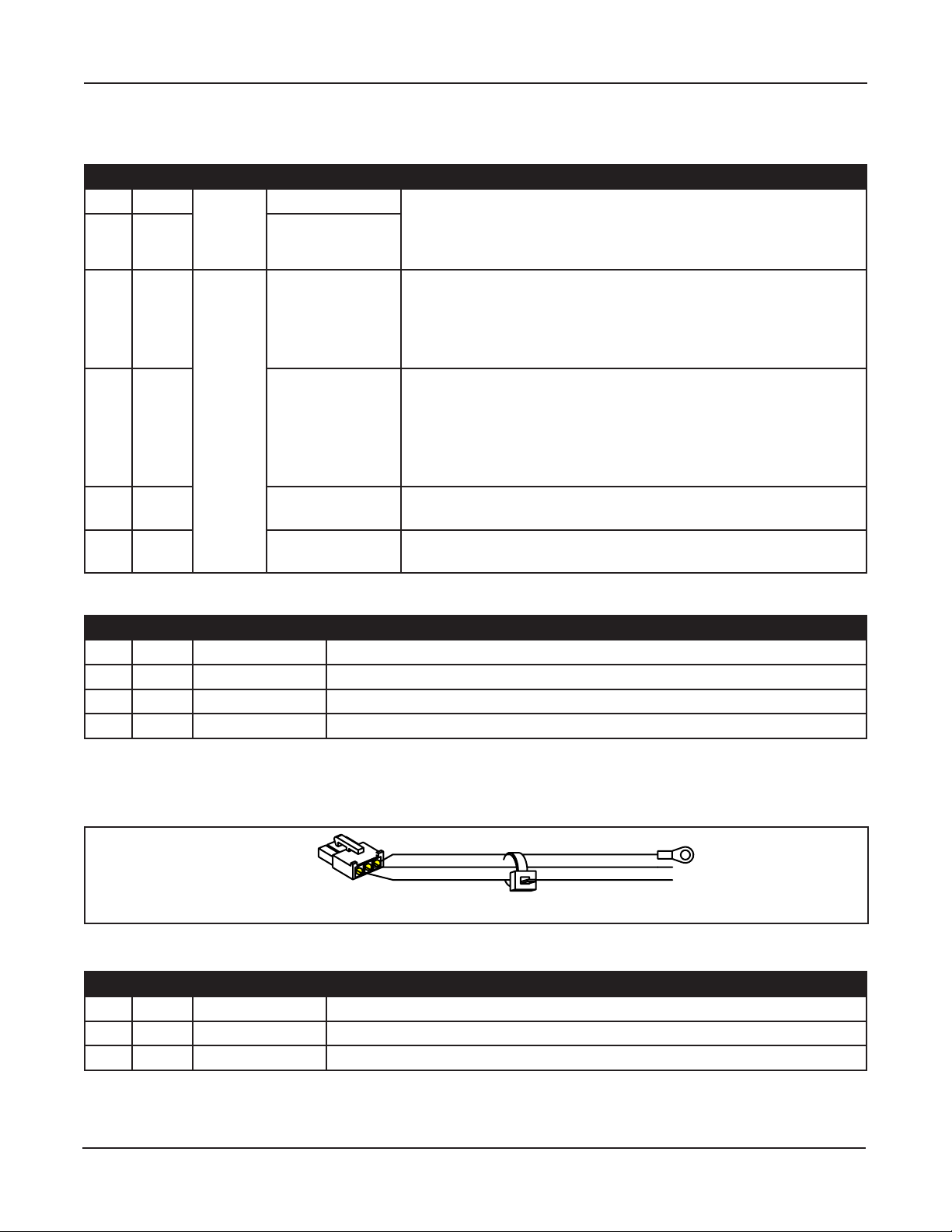
Secon 3a. Main Harness ................................................................3-7
Secon 3b. Power Harness ...............................................................3-8
Secon 3c. Motor Harness (300/400/500) ..................................................3-9
Secon 3d. Motor Harness (710/8310/8710)................................................3-9
Secon 3e. Fuses.......................................................................3-9
.............................
Secon 4a. Swing Door Posions.........................................................4-10
Secon 4b. Adjustments................................................................4-10
Secon 4c. Status LEDs .................................................................4-14
.........................
....................................
Secon 6a. Panic Breakout Latch/Switch (Open Loop Connuous Safety Circuit)..................6-16
Secon 6b. Panic Breakout Latch/Switch (Closed Loop Connuous Safety Circuit).................6-17
...............................
Secon 7a. GT-300-400-500 Single Door...................................................7-19
Secon 7b. GT-300-400-500 (Simultaneous Pair) ............................................7-20
Secon 7c. GT-300-400-500 (Simultaneous Pair w/One Magnum 4A Control) ....................7-21
Secon 7d. GT-710-8310-8710 Single Door ................................................7-22
Secon 7e. GT-710-8310-8710 (Simultaneous Pair)..........................................7-23
Secon 7f. GT-710-8310-8710 (Simultaneous Pair w/One Magnum 4A Control) ..................7-24
Secon 7g. GT-1400 Single Fold with One Magnum 4A Control ................................7-25
Secon 7h. GT-1400 Bi-Fold with Two Magnum 4A Controls ..................................7-26
Secon 7i. GT-1400 Bi-Fold with One Magnum 4A Control ....................................7-27
...........................
Secon 8a. Transformer Installaon and Wiring for 240 Volts .................................8-28
........................................

ii
Magnum 4A Control Wiring and Adjustment Manual www.NabcoEntrances.com
Part #C-00084 Rev. 9-09-16
WARNING LABELS
Warning labels are universal and used to alert an individual of potential harm to one’s self or to others. The following warning
labels are listed in a hierarchy order that denes the most potential danger rst, and the least potential danger last. Please refer
to this page in the event that a warning label is displayed within this manual and further denition needs to be explained.
high
some
is present.
may result in a minor injury
DANGER
WARNING
CAUTION

iii
Rev. 9-09-16 Part #C-00084
www.NabcoEntrances.com Magnum 4A Control Wiring and Adjustment Manual
GENERAL SAFETY RECOMMENDATIONS
Header.
WARNING
DANGER
CAUTION
DANGER
CAUTION
CAUTION
CAUTION

1-4 Scope
Magnum 4A Control Wiring and Adjustment Manual www.NabcoEntrances.com
Part #C-00084 Rev. 9-09-16
The purpose of this manual is to familiarize the installer with the proper installation and operation of this
system. It is essential that this equipment be properly installed and operational before the door is used
by the public. It is the installer’s responsibility to inspect the operation of the entrance system to be sure
it complies with any applicable standards. In the United States, ANSI Standard 156.10 (Used to cover Full
Energy doors) and ANSI Standard 156.19 (Used to cover Low Energy doors) apply. Other local standards
or codes may apply. Use them in addition to the ANSI standards.
The owner should determine the door is operating properly and should immediately call for service if
trained technicians.
XNew or Existing Swing Door systems.
XNew or Existing Fold Door systems
X
This manual offers step by step instructions.

Rev. 9-09-16 Part #C-00084
www.NabcoEntrances.com Magnum 4A Control Wiring and Adjustment Manual
Geng Started 2-5
►
►Replaces all Magnum controls.
►Replaces the analog swing control (requires two controls for sim pair installations).
►
►
►Digital parameter settings for repeatability.
►
controls required for sim pair and bifold applications).
►
►
►
encoder motor.
►
►
►Two transistor outputs with programmable functionality for air curtains or other devices.
►
►Recycle on object detection during Opening cycle with all motors.
►
►Full Power or Low Energy application capability.
►
might be commonly used. Onsite wiring may be different from that shown.
Table 2-1 Sensors
Sensor Part Number Function Power Source Current Consumption
Acuvision Infrared
Acuwave Infrared
Infrared
Infrared
Table 2-2 Modules
Module Part Number Function Power Source Current Consumption
RF Signal Transmission 50mA
Multi Module Programmable Relay 40mA

Magnum 4A Control Wiring and Adjustment Manual www.NabcoEntrances.com
Part #C-00084 Rev. 9-09-16
2-6 Geng Started
Table 2-3 Power Wiring
Wiring Power Current Consumption
Maximum Input 500mA (0.5amps)
Output (Available for Accessories) 500mA (0.5amps)
Available Wire Size for Incoming Power 14 AWG -
-
-
Fuses -
-
►Sensors
►Modules
►Accessories
►Auxiliary Equipment
If current draw exceeds 500 mA (0.5 amps) the installer must utilize an auxiliary power supply
such as the
The Opus 10 Control must Not be used to output power to:
►Magnetic Locks
►Electric Strikes
To determine if an auxiliary power supply must be used, add the total current draw of all devices. Please
50 mA
An Auxiliary Power Supply does not need to be used.
CAUTION

Rev. 9-09-16 Part #C-00084
www.NabcoEntrances.com Magnum 4A Control Wiring and Adjustment Manual
Magnum 4A Board Terminals 3-7
.
Figure 3-1
DN 0596
F1
J2
J4
J5
J1 Terminal Connector Harness
J1 Input Signal Main
J2 Auxiliary Power Main
J4 Incoming PowerPower
J5 Motor Motor
F1 Reseable Fuse
Non-Replaceable
N/A
F2 Not ReseableFuse N/A
LED
TRANSFORMER
AUX
PWR
J2
O
F
F
12 4
3
J5
AC IN
SW2
SW1
F1
RELAY RELAY
J4
TDAS
SIGNAL
INPUT
TDPG
LCHK
CLOSE
Fuse 1: 0.5A 24 VAC
STOP
OPEN
BCHK
CURRENT
LIMIT MOTOR
J1
R28
MAGNUM 4A
F2
Fuse 2: 5A
120/240
Capacitor
MOV
F2
Main Harness
►
►
Please see .
Figure 3-2
DN 0588
123456
321
2
1
54
6
123
4
Brown
Orange
Violet
White
Red
Black
Orange
Blue
Red
Signal Input Harness to Connector J1
Auxiliary Power Harness to
Connector J2
Switch Harness
(to operator posion switches)
6 Pole Terminal Block
connected.

Magnum 4A Control Wiring and Adjustment Manual www.NabcoEntrances.com
Part #C-00084 Rev. 9-09-16
3-8 Magnum 4A Board Terminals
Table #-1
Pole Wire Harness Circuit Description
1 Aux Pwr X
XSensor must not exceed 0.5 amp current draw.
XIf Sensor exceeds 0.5 amp current draw Fuse (F1) will trip. A
separate power supply must be used.
Orange
Terminal X
X
• Stop door during opening
• Prevent door from moving when door is fully closed
X
4 White X
on pull side of door.
X
• Prevent door from opening if already closed
•
X
5Red
6 Activation
door is activated.
Table #-2
Pin Wire Circuit Description
1 Orange
Red
4
Power Harness
.
Figure 3-3
DN 0606
1
Table #-3
Pin Wire Circuit Description
1 Green Incoming Ground wire
White Incoming Neutral wire

Rev. 9-09-16 Part #C-00084
www.NabcoEntrances.com Magnum 4A Control Wiring and Adjustment Manual
Magnum 4A Board Terminals 3-9
Motor Harness
Figure 3-4
DN 0559
(J5) Motor Connector Brake Module Connector
plugs into J5
Motor Brake Module
Motor Leads
LED
TRANSFORMER
AUX
PWR
J2
J5
AC IN
F2
SW2
SW1
F1
RELAY RELAY
J4
TDAS
SIGNAL
INPUT
TDPG
LCHK
CLOSE
Fuse 1: 0.5A 24 VAC
STOP
OPEN
BCHK
CURRENT
LIMIT
MOTOR
J1
R28
MAGNUM 4A
Fuse 2: 5A 120/240
Capacitor
MOV
O
F
F
12 4
3
X
X
Figure 3-5
DN 0597 Connector plugs
into (J5)
Motor Leads
Motor Input
(J5) Motor Connector
LED
TRANSFORMER
AUX
PWR
J2
O
F
F
12 4
3
J5
AC IN
SW2
SW1
F1
RELAY RELAY
J4
TDAS
SIGNAL
INPUT
TDPG
LCHK
CLOSE
Fuse 1: 0.5A 24 VAC
STOP
OPEN
BCHK
CURRENT
LIMIT MOTOR
J1
R28
MAGNUM 4A
F2
Fuse 2: 5A
120/240
Capacitor
MOV
Fuse Amp Usage Description
F1 .5 Resettable X
XProtects
5 Not Resettable

4-10 Adjustments and Status LEDs
Magnum 4A Control Wiring and Adjustment Manual www.NabcoEntrances.com
Part #C-00084 Rev. 9-09-16
Do Not touch other parts of the Magnum 4A Control board with a screwdriver or
anything else metal. Damage to electrical circuitry may occur.
Figure 4-1 Door Positions
DN 0035
Back
Check
Latch
Check
Main Speed
Door Cycle
Closed
Position Description
Opening Range from fully closed to 10° from fully open.
10° from fully open to fully open.
Range from fully open to 10° from fully closed.
10° from fully closed to fully closed.
Adjustments
DN 0560
Adjustment Poten ometers
Dip Switch (SW1)
SW2
R2 R3 R4 R5 R6 R7 R8
TDAS TDPG LCHK CLOSESTOP OPEN BCHK
CURRENT
LIMIT
R28
LED
O
F
F
12 4
3
SW1
Slide Switch (SW2)
.
CAUTION
Figure 4-2 Adjustment Locations

Adjustments and Status LEDs 4-11
Rev. 9-09-16 Part #C-00084
www.NabcoEntrances.com Magnum 4A Control Wiring and Adjustment Manual
Figure 4-3 Dip Switch (Displayed in ON position)
DN 0561
OFFSWITCHES SHOWN IN “ON” POSITION
1 Not Used
2 OFF: Closed Loop Safety / ON: Open Loop Safety
3 OFF: Push-N-Go active / ON: Push-N-Go Inactive
4 OFF: Sequential Mode / ON: Timer Mode
Table 4-1 Dip Switch Settings
Switch Adjustment
1 Not Used
On Open Loop Safety XSafety triggered when contact is closed by a Switch or Sensor
Off X* Safety triggered when contact is opened by a Switch or Sensor
On X
Off X
active in any position.
X
XDoor opens when pushed.
• Switch 4 must be turned “On” for door to time out and close.
4 On Timer Mode XDoor will open, time out and then close.
Off Sequential Mode XOne activation opens door, second activation closes door.
►Upper Position
• Used for Low Energy Operators.
• Motor power is reduced to approximate ANSI 156.19 Low Energy Standards.
►Lower Position
• Used for Standard Full Automatic Operators.
•
• Motor power is increased to approximate ANSI 156.10 Standards.
It is recommended to set door speeds as slow as the owner will accept, and no more than the applicable
ANSI Standards. Use a stopwatch for assistance. Please see .
► a parameter.
► a parameter.

4-12 Adjustments and Status LEDs
Magnum 4A Control Wiring and Adjustment Manual www.NabcoEntrances.com
Part #C-00084 Rev. 9-09-16
point. Potentiometer settings might need to be adjusted accordingly. After each adjustment, wait at least 5
seconds before testing.
All electrical troubleshooting or service must be performed by trained, qualied
technicians and comply with all applicable governing agency codes.
Table 4-2 Potentiometers
Potentiometer Description
Stop XStops or slows door when object is detected in path of opening door (not yet in
X
•
•
XAlso adjusts the power to the motor when the door is held open for extended periods
the motor overheating at hold open allowing the door to close as well as reducing
stress on mechanical and electrical components. To adjust power applied to the door
be reduced according to the “STOP” setting. If the door begins to slowly drift close
full open position. Door should hold open and not drift close.
If door still drifts close, continue increasing STOP power until the door holds
open against the door stop.
Each time an adjustment is made, the door must be allowed to close, and then
Event Action
Object is detected in path of
opening door by Door Mounted
Sensor that is mounted on swing
side of door and connected to
X
X
X
Open Sets opening speed of door.
Event Action
Door opened at wrong speed. X
X
X
Event Action
adjustment.
X
X
X
CAUTION

Adjustments and Status LEDs 4-13
Rev. 9-09-16 Part #C-00084
www.NabcoEntrances.com Magnum 4A Control Wiring and Adjustment Manual
Potentiometer Description
TDAS
(Time Delay Activating Signal)
Determines how long door will stay open after activation (or input signal) is released.
and
Full Automatic door
Low Energy door
Event Action
adjustment.
X
X
X
X
stay open.
TDPG
Full Automatic door
Low Energy door
Event Action (Full Automatic doors)
adjustment after door is pushed.
X
X
X
stay open.
X
operators that use a clutch gear, Push n Go is only active from the fully closed position
once the door is manually pushed out of latch position.
XIf Push n Go is desired for all door positions, a clutchless operator must be ordered.
(Not used on
Full Automatic door
Low Energy door
Event Action
adjustment.
X
X
X
(Not used on
Full Automatic door
Low Energy door
Event Action
adjustment.
X
X
X
Adjusts how hard the door will push against an obstacle (while opening) before recycling.
X
X
adjustments are made to the door and door operation is satisfactory.

4-14 Adjustments and Status LEDs
Magnum 4A Control Wiring and Adjustment Manual www.NabcoEntrances.com
Part #C-00084 Rev. 9-09-16
Potentiometer Description
Event Action
Recycle sensitivity needs
adjusting.
X
until all other adjustments
are made.
XWhen recycle is triggered, door will stop and
coast to a close. Wait at least (5) seconds before
Reactivating.
X
X
• Decreased Recycle Sensitivity.
X
• Increased Recycle Sensitivity.
X
adjusted according to door weight and speed.
X
stop door from opening.
at any instant within
the Swing door cycle. This helps to identify when the Swing door system is functioning properly. Please
see .
Figure 4-4 LED Indicators
DN 0558
Red LED
Green LED
LED
TRANSFORMER
AUX
PWR
J2
F1 TDAS
SIGNAL
INPUT
TDPG
LCHK
CLOSE
Fuse 1: 0.5A 24 VAC
STOP
OPEN
BCHK
J1
Table 4-3 Status LED Indicators
LED Status Description
Green Indicates door position during an open and closed cycle.
Indicator Action
Fast Flashing Door is opening.
On Solid
Slow Flashing Door is closing.
Off
Red Safety
Swing door cycle.
Indicator Action
Slow Flashing XDoor mounted Sensor on Swing side of door is activated.
X
Fast Flashing X
activated.
X
On Solid X

Connect Incoming 120 VAC Wires 5-15
Rev. 9-09-16 Part #C-00084
www.NabcoEntrances.com Magnum 4A Control Wiring and Adjustment Manual
Disconnect 120 VAC power prior to making any electrical connections. Failure to
do so may result in serious personal or fatal injury. When uncertain whether power
supply is disconnected, always verify using a voltmeter.
Notice: Wiring must meet all local, state, federal or other governing agency codes.
Ensure all power is disconnected.
All high voltage electrical connections must be made by licensed electricians.
a.
Keep all Incoming 120 VAC wiring separate from low voltage wiring within Header.
a.
DANGER
CAUTION

6-16 Wiring Safety Devices
Magnum 4A Control Wiring and Adjustment Manual www.NabcoEntrances.com
Part #C-00084 Rev. 9-09-16
Do Not touch other parts of the Magnum 4A Control board with a screwdriver or
anything else metal. Damage to electrical circuitry may occur.
feature and disable the Operator.
Turn OFF Power.
.
DN 0060
EXT
INTERIOR SIDE EXTERIOR SIDE
Figure 6-1
.
Figure 6-2
DN 0061
Connects to
Panic Breakout Limit Switch
Brown
Black Brown
Black
.
CAUTION

Wiring Safety Devices 6-17
Rev. 9-09-16 Part #C-00084
www.NabcoEntrances.com Magnum 4A Control Wiring and Adjustment Manual
Figure 6-3 Wire Panic Latch for Full Automatic doors
DN 0566D
Part # 22-10065
Harness Assy
for Single
Part # 12-13166
Motor Fuse
(GT300, 400, 500)
Panic Latch must be flipped.
Arrow marked "EXT" must
point to the Interior of
building.
(Contacts must close
when door is broken out)
Back Check Limit Switch
(Black and Brown)
Breakout Limit Switch: N.O.
Terminals 3 and 5
MUST be connected to Continuous Safety input,
Breakout Limit Switch Signal and Panic Latch Signal
When the unit has Panic Breakout feature,
Panic Latch Kit
Part # 11- 0941
Red
Red
Brown
Black
Red: Comm, Blue: N.C.
for Magnum Board
300/400/500 Harness
Part # 21-9934
BROWN
BLACK
RED
WHITE
VIOLET
ORANGE
Operator Assembly
USE THESE CONNECTIONS ON INSWING
DOORS WITH PANIC BREAKOUT
1
6 3
542
LED
TRANSFORMER
O
F
F
12
AUX
PWR
4
J2
3
J5
AC IN
F2
SW2
SW1
F1
RELAYRELAY
J4
TDAS
SIGNAL
INPUT
TDPG
LCHK
CLOSE
Fuse 1: 0.5A 24 VAC
STOP
OPEN
BCHK
CURRENT
LIMIT
MOTO
J1
R28
MAGNUM 4A
R
Fuse 2: 5A
120/240
Capacitor
MOV
Please see .
Figure 6-4
DN 0565
EXT
.
The new “Fail Safe” safety circuit feature on the Magnum control is only available on recent controls as

6-18 Wiring Safety Devices
Magnum 4A Control Wiring and Adjustment Manual www.NabcoEntrances.com
Part #C-00084 Rev. 9-09-16
Turn OFF Power.
arrow points to the Exterior
.
DN 0644
EXT INTERIOR SIDEEXTERIOR SIDE
Figure 6-5
Please see .
.
Figure 6-6 Panic Latch (Fail Safe)
DN 0570
BROWN
BLACK
RED
WHITE
VIOLET
ORANGE
23456 12356
To Magnum Control
Safety with Lockout
during door swing
To Terminal #5
Normally Closed Contacts
Continuous Safety
Normally Closed Contacts
Red
Red
Part # 11- 0941
Panic Latch Kit
TERMINAL BLOCK
#1 BROWN
#2 ORANGE
#3 VIOLET
#4 WHITE
#5 RED
#6 BLACK
24VAC NEUTRAL
24VAC HOT
CONTINUOUS SAFETY
SAFETY WITH LOCKOUT
ACTIVATION
When using normally closed safety, all panic breakout devices connected to
continuous safety must be wired in series. If sensor contacts
or a panic latch opens, the door can not activate.
BROWN
BLACK
RED
WHITE
VIOLET
ORANGE
23456 1234
To Magnum Control
Safety with Lockout
To Terminal #5
Normally Closed Contacts
Continuous Safety
Normally Closed Contacts
Red Red
RedRed
SIMULTANEOUS PAIRS
SINGLE DOORS
Panic Latch must be positioned so that
arrow marked "EXT" points to exterior of building.
(Contacts must open when door is broken out)
Panic Latch must be positioned so that
arrow marked “EXT” points to exterior of building.
(Contacts must open when door is broken out)
Safety with Lockout
(Overhead Sensors)
Normally Closed Contacts
On double egress doors
using two overhead safety
sensors with normally closed
safety, outputs of both
sensors must be wired in
series.
(Overhead Sensor)( Door Mounted Sensor)
Continuous Safety
Normally Closed Contacts
(Door Mounted Sensor)
To Terminals
4 and 5
COMMON

Wiring Diagrams (General) 7-19
Rev. 9-09-16 Part #C-00084
www.NabcoEntrances.com Magnum 4A Control Wiring and Adjustment Manual
DN 0567
Off
HoldOpen
On
Off
White
Black
Red
Activation
Safety with Lockout
during door swing Continuous Safety
24 VAC AUX Output
for sensors
TERMINAL BLOCK
#1 BROWN
#2 ORANGE
#3 VIOLET
#4 WHITE
#5 RED
#6 BLACK
24VAC NEUTRAL
24VAC HOT
CONTINUOUS SAFETY
SAFETY WITH LOCKOUT
24VAC COMMON
ACTIVATION
Ground
Black(Hot)
Black
Black
White (Neutral)
Part # 21-9934
300/400/500 Harness
for Magnum Board
Red: Comm, Blue: N.C.
White: Comm, Green: N.
C.
Black
Brown
Common N.O.
Device
Not Used
Typical
Mat or
Wall Switch
24 VAC
Input
Typical Sensor
Device
If Rocker Switch is not Required
Connect the Activation Signals to
Terminals 5 and 6 Directly
Part # 10-3528
RS-12 Rocker Switch
Red
Red
Part # 11- 0941
Panic Latch Kit
When the unit has Panic Breakout feature,
Breakout Limit Switch Signal and/or Panic Latch Signal
MUST be connected to Continuous Safety input,
Terminal Block #3 
Breakout Limit Switch: N.O.
(Black and Brown)
Latch Check Limit Swit
ch
Part # 22-10065
Harness Assy
for Single
Back Check Limit Switch
BROWN
BLACK
RED
WHITE
VIOLET
ORANGE
Ter
#5
to Te rminal
#5 (red)
to Te rminal
#5 (red)
to Te rminal
#5 (red)
to Te rminal
#5 (red)
to Te rminal
#5 (red)
Panic Latch must be flipped.
arrow marked "EXT" points into the building.
(Contacts must close when door is broken out)
to Te rminal
#5 (red)
123456
ON/OFF
ROCKER
SWITCH
120 VAC
Part # 12-13166
Motor Fuse
(GT300, 400, 500)
LED
TRANSFORMER
O
F
F
12
AUX
PWR
4
J2
3
J5
AC IN
F2
SW2
SW1
F1
RELAY RELAY
J4
TDAS
SIGNAL
INPUT
TDPG
LCHK
CLOSE
Fuse 1: 0.5A 24 VA C
STOP
OPEN
BCHK
CURRENT
LIMIT
MOTO
J1
R28
MAGNUM 4A
R
Fuse 2: 5A
120/240
Capacitor
MOV
Other manuals for GT 300
2
This manual suits for next models
6
Table of contents
Other Nabco Gate Opener manuals
Popular Gate Opener manuals by other brands

CAME
CAME BXV04AGS installation manual

Nice
Nice THOR Series Instruction manual and spare parts catalogue

Allstar
Allstar GS1000 Installation and owner's manual

DITEC
DITEC 0DT869 Installation manual, maintenance, use

CAME
CAME FROG series installation instructions

CARDIN ELETTRONIC
CARDIN ELETTRONIC BL Series manual