Rotech PR.45E User manual
t: +61 07 3205 1123 www.rotech.com.au e: [email protected]
Vehicle Access Control
Pedestrian Access Control
Safety & Security Equipment
Installation Instructions
Please read these instructions fully before installing
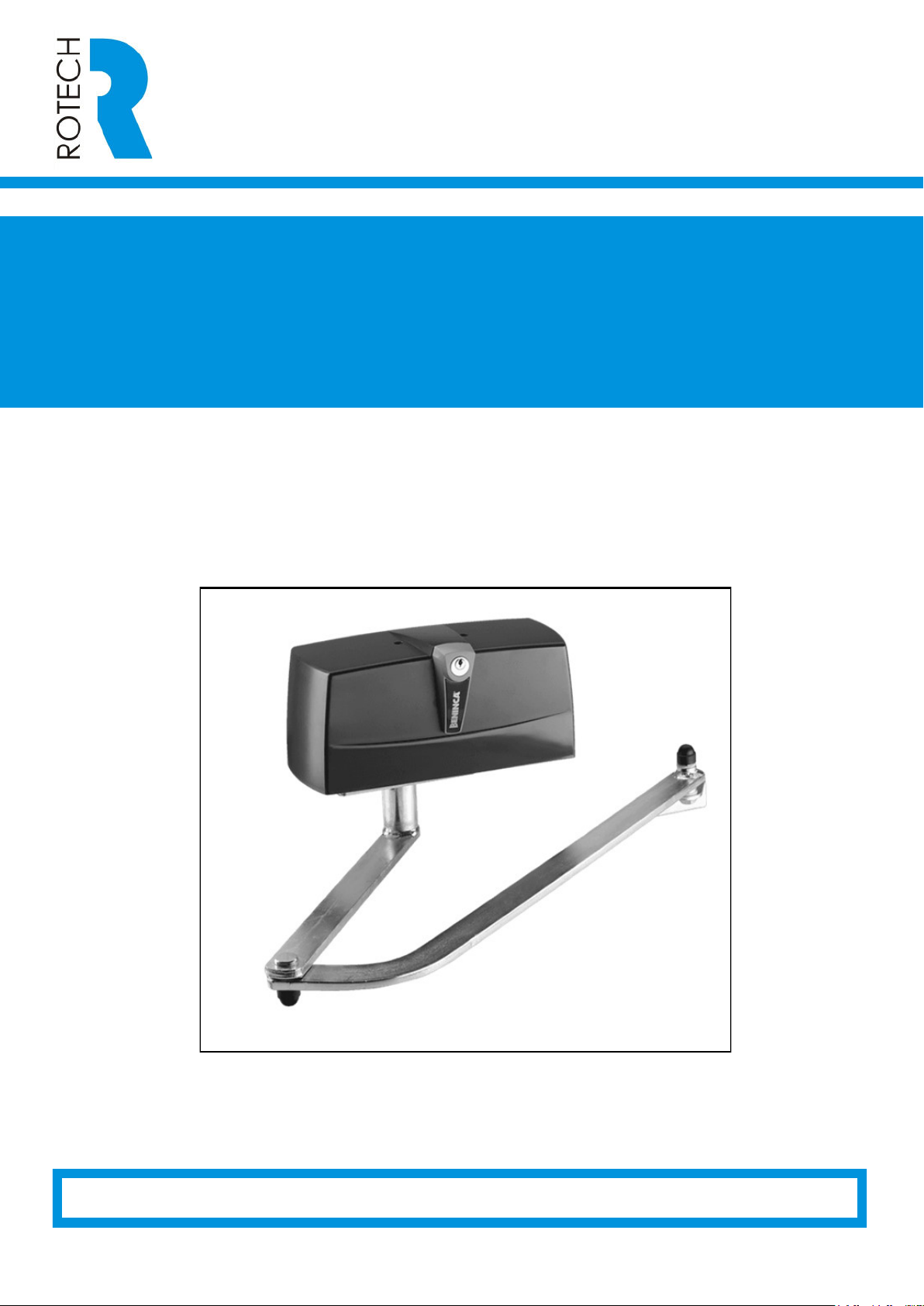
Sentinel PR Articulated Arm
Swing Gate Operator (v02/23)

4
5
332
130
112
160
365
65042
170
115
160
165
Fig.1
Overall dimensions Technical dataPR.45EPR.45ELPR.45ERPR.45E24Power supply230 Vac 50/60 HzMotor feed230 Vac24 VdcPower drawn390 W325 W390 W 215 WCurrent drawn1,75 A1,45 A1,75 A9 ATorque325 Nm300 Nm250 Nm320 NmOperating time13 s20 s7 s9 sJogging30%40%80%*Door leaf max. weight300 kg200 kg400 kgDoor leaf max.3 m4 m2 m 3 mCapacitor10 µF--Noise level<70 dB (A)Lubrication
Agip GR MU EP/2
IP classIP44Operating temp.-20°C/+50°CWeight13 kg

6
7
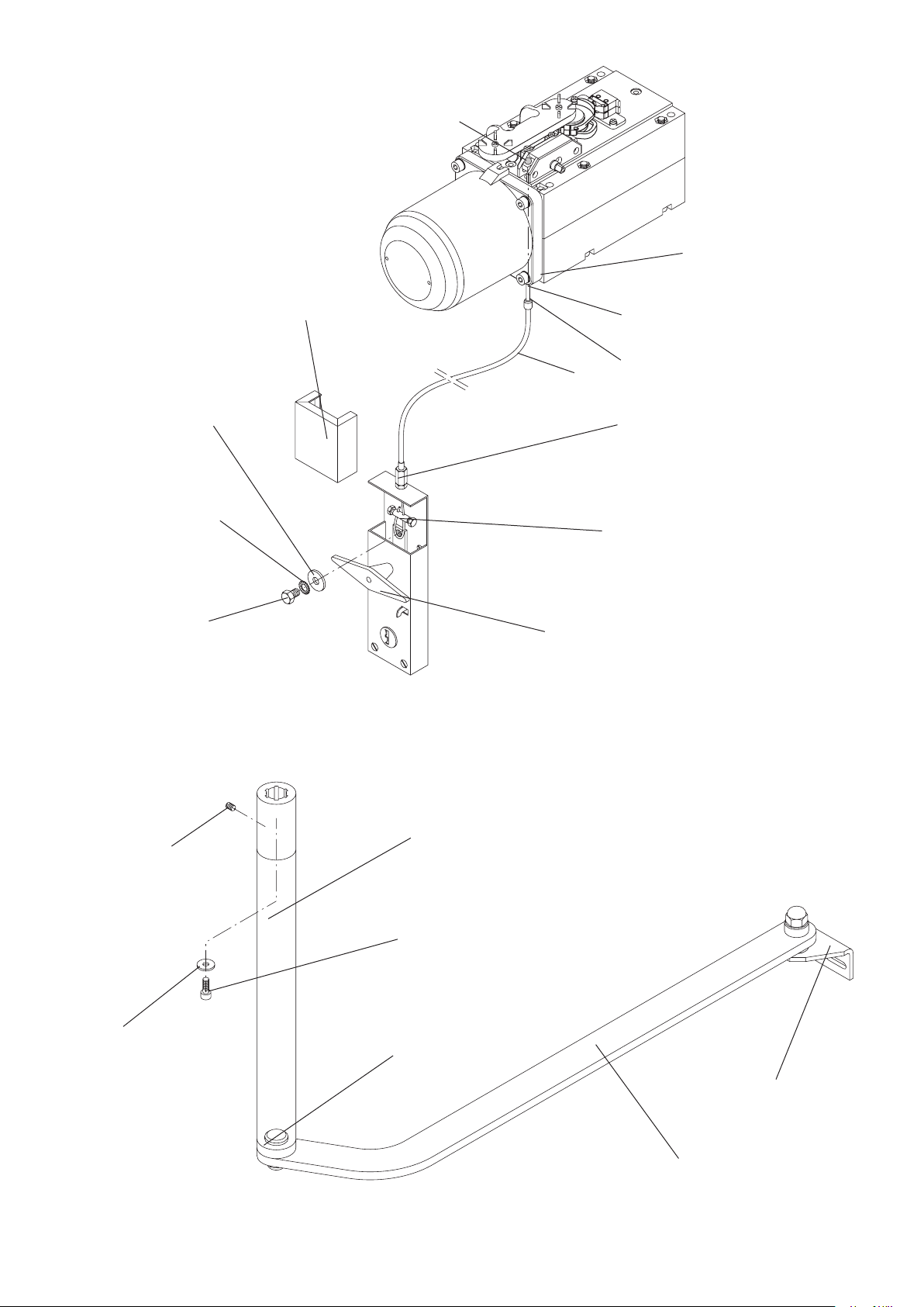
Fig.2 ADelay.Anticipate.GMV1LV2Fig.3
C
6
7
Fig.4 FWire release art. DU.MS45. Screw M8x10 UNI 5739. Washer M8 DIN 6798E. Handle with plate. Clamp.Register. Washer 9x24 UNI 6593. SCover.LGKC Screw M6x10 UNI 5927 Bracket Washer Ø6.6x18 UNI 6953 Screw M6x16 UNI 5931 Connecting rodPin for connecting rod LeverArt. DU.E2

8
9
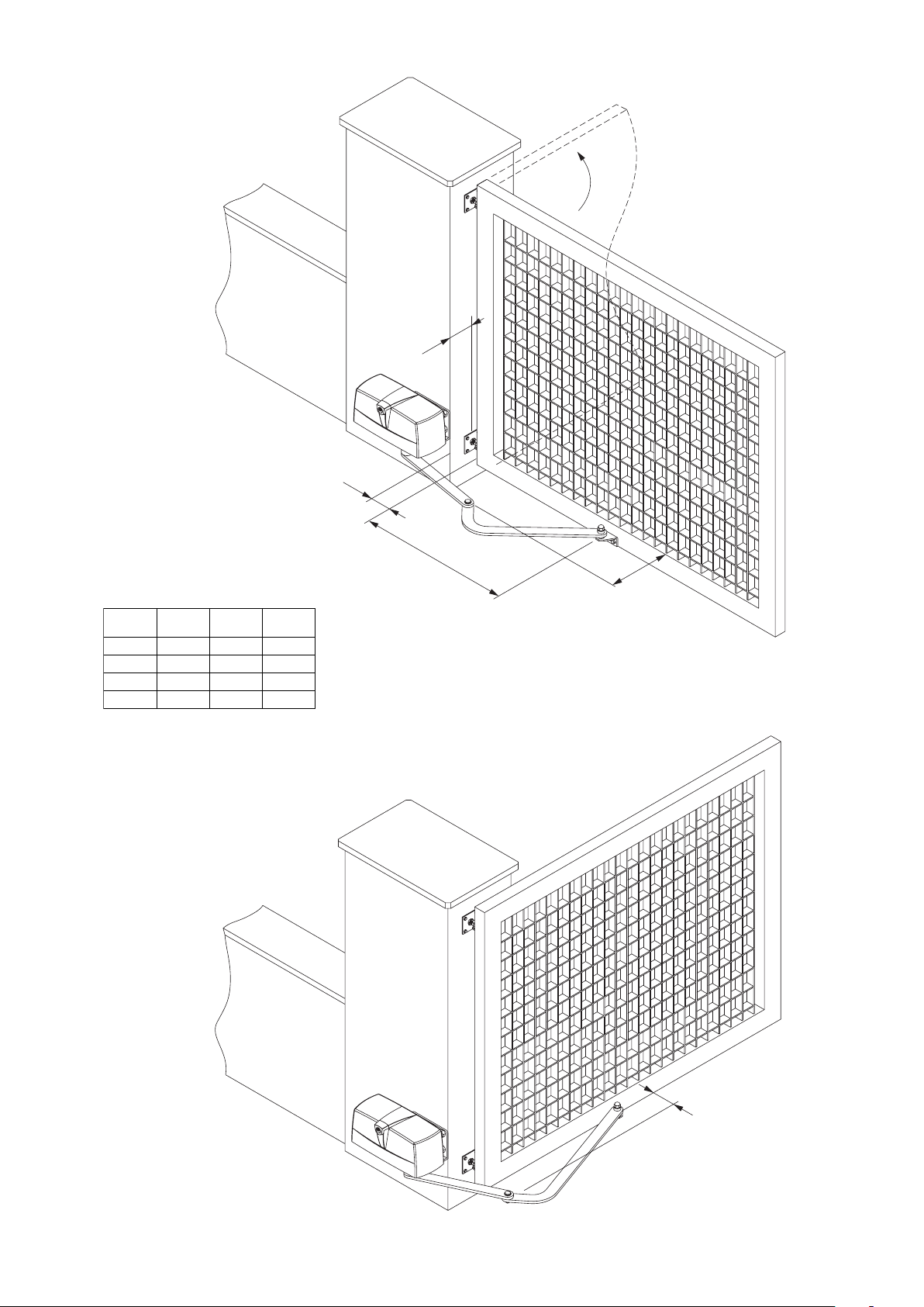
Fig.5
Fig.6
50
AB150
200
250
3008838518288008462771811173228429466475469468
CD
*When opening it’s necessary that the arm has at least the signaled space.Max 130° opening.
DBC112A100
2040100*160*18123760775
8
9
Fig.7
Fig.8
ABC70
D
50
AB
100150
200688651606550390453503553154137135138CD
11
412
RG 58
6
3x1,5 min230 V
521
2x1,52x1
2x1A
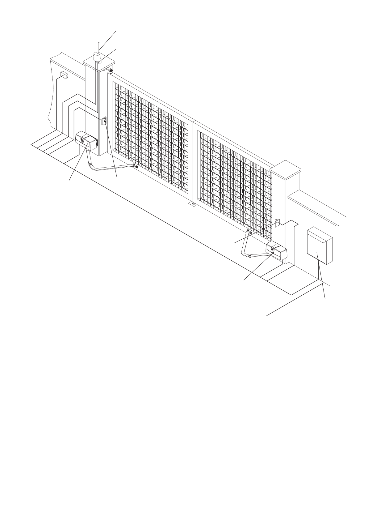
N.B.: The power cables must be kept separated from the auxiliary cables. Legend:1 Motoreducer PREMIER2 Photo-electric cells FTC/FTM3 Key selector CH (external) or digital keyboard4 Flash-light LAMP5 Antenna AW
A4x1
APR.45E / L / R 4x1,5mm2PR.45E24 2x1,5mm2 + 3x0,5mm2

12
13
Warning•Before installation, carefully read the instructions hereunder.•It is strictly forbidden to use the item PREMIER for applications other than the intended uses described inthese instructions.•Instruct the user on how to use the system.IntroductionThank you for choosing our PREMIER ratiomotor. All items in the wide Benincà production range are the result of twenty-years’ experience in the automatism sector and of continuous research for new materials and advanced technologies. We are, therefore, in the position to offer higly reliable products that due to their power, effectiveness and useful life, fully satisfy the nal user’s requirements.All our products are manufactured to the existing standard and are covered by warranty. Possible injury to people or accidents caused by defects in construction are covered by a civil liability policy drawn up with one of the major insurance companies.General notesFor a good operation of the automatic system the door to be automated must feature the following character-istics:•Rugged and stiff door leaves.•Efcient hinges.•The door leaves should be moved by hand without any friction for the entire stroke.•The doors should be complete with a catch in the closing phase.In the negative, replace the faulty parts. Reliability and safety of the automatic system depend on the gatestructure.General featuresThis automatism has been designed to automatize doors, the dimensions of which do not allow to use tra-ditional actuators.It is equipped with an articulated arm and with a limit switch, (PREMIER). The operations are smooth and noi-seless. It is easy to be assembled and, thanks to its pleasant design, it meets the most demanding needs.The emergency block is simple and safe thanks to the lever with personalised key.ConnectionsPR.45E/PR.45EL / PR.45ER:Brown Motor phase and capacitorGrey or Light blue CommonBlack Motor phase and capacitorYellow/Green Earth - compulsory pursuant to regulations in forceThe limit switch contacts are connected in series to the two motor phases. If, after an opening control, the motor starts the closing movement, it is sufcient to reverse the brown wire with the black one in the control unit.PR.45E24:Red Motor +Black Motor -Carry out the limit switch connections to the control unit.If, after an opening control, the motor starts the closing movement, it is sufcient to reverse the red wire with the black one in the control unit.As regards the torque adjustments and the operating modes, please read instructions given in the control unit manual.To adjust the limit switches (Fig. 3)The PR.45E unit is equipped with built-in limit switches for both opening and closing phases. Proceed as follows:•Release the actuator (see paragraph “Release by hand”)•Remove the cover M from the release lever L.•Loosen the screw V1 and remove the release lever L.•Loosen the screws V2 and remove the cover.

15
•Close the gate until it touches the stopper.•Loosen the tting screw of the cam and adjust the cam until triggering of the micro-switch.•The same operation should be carried out with the other cam, with completely open gate.•Reset the automatic operation and check the correct positioning of the cams by opening and closing thegate for a few times.•Tighten the xing screws of the cams.Note:The PR.45E /R/L (230Vac) models feature a thrust of some seconds on the stoppers without damaging the gear motor. If required, it is therefore possible to select the timed operation, thus excluding the limit switches.In the PR.45E24 model, cams should be adjusted and limit switches should be connected to the control unit.Release by handAs regards the manual operation, should a power failure occur two solutions are available for the PREMIER unit :Release from inside (Fig. 3)•Insert the customised key C, and turn it clockwise.•Turn the release lever L for at least 90° clockwise.•At this point, the reduction gear is released and the gate can be moved by had.•To reset the normal operation, move the lever L to the original position and turn key C anti-clockwise. Whenthe unit is powered again, the normal operating mode will be reset with the rst movement of the gate.Internal-external release with cord (Item DU.MS45) (Fig. 4 - optional)•Insert the steel cable C on lever L.•Introduce the sheath G with the cable gland K until it reaches the hole F.•Fit the steel cable C in the handle, according to Fig. 4.•Turn the handle to release.•By turning the handle again, the rst operation will reset the normal operating mode.ApplicationsApplication suitable to max 90° opening inward (g. 5.Application suitable to max 130° opening (g. 6).P.N. When opening it’s necessary that the arm has at least the signaled space.Application suitable to opening to the outside (gg. 7 - 8).CAUTIONThe civil liability policy, which covers possible injuries to people or accidents caused by defects in construc-tion, requires the system to be to existing standard and to use original Benincà accessories.

22
Pos.PR.45E - PR.45EL Description Code
1CarterCover96863552PiastraPlate96861293Camme nec.Limit stop cam96861584Albero motoreShaft96861685PignoneGear96861706GuarnizioneGasket96861697Albero d'uscitaOutput shaft96861328BlisterBlister96863549Pignone
Gear
968601110Leva sblocco
Release lever
968635611Piastrina
Plate
968635712Staffa
Bracket
9686358A
Calotta PR.45E
Motor cup9686131
Calotta PR.45EL
Motor cup9686133
234A597681012111
12
10
11
9
8
7
6
5
4
3
2
1
A
This manual suits for next models
3
Table of contents
Other Rotech Gate Opener manuals


