iii
Rev. 9-24-14 Part #15-10683
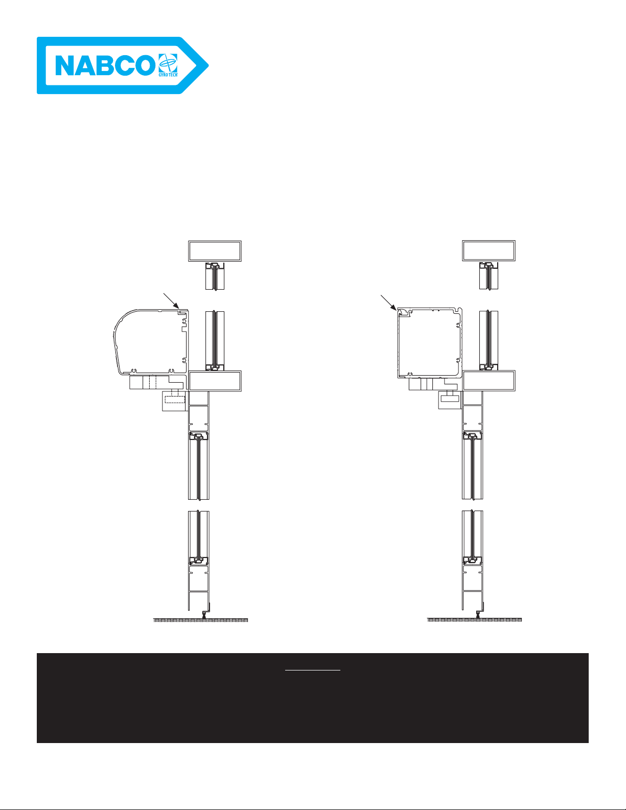
www.NabcoEntrances.com GT 710-8710 Swing Door System Low Energy Operator
GENERAL SAFETY RECOMMENDATIONS
Read this “General Safety Recommendations” section before installing, operating
or servicing the automatic door. Failure to follow these practices may result in
serious consequences.
Notice: Read, study and understand the operating instructions contained in, or referenced
in this manual before operating. If you do not understand the instruction, ask the
installing qualied technician to teach you how to use the door.
Do not install, operate or service this product unless you have read and
understand the General Safety Recommendations, Warning Labels, Installation
and Operating Instructions contained in this manual. Failure to do so may result in
bodily injury, or property damage.
Notice: This manual and the owner’s manual must be given to and retained by the
purchasing facility or end user.
►If the door appears broken or does not seem to work correctly, it should be immediately
contacted for corrective action.
►Disconnect power at the fused disconnect during all electrical or mechanical service.
When uncertain whether power supply is disconnected, always verify using a voltmeter.
►
technicians and must comply with all applicable governing agency codes.
►It is the responsibility of the installing door technician to install all warning and
instructional labels in accordance with ANSI 156.19.
►It is the responsibility of the purchasing facility or end user to keep warning and
instructional labels and literature legible, intact and with the door.
►Replacement labels and literature may be obtained from local NABCO Entrances, Inc.
distributors. If the name of the local distrubutor is unknown, contact NABCO Entrances,
Inc. at 1-877-622-2694 for assistance.
Do not place nger or uninsulated tools inside the electrical controller. Touching
wires or other parts inside the enclosure may cause electrical shock, serious
injury or death.