ALIGNMENT
METHOD
IMPORTANT
I
The tape path (heads, tape
guides,
capstan, plnch roller) should be cleaned and degaussed before alignment.
I
This tape recorder is designed to work well with a variety of tapes, however, maxlmum performance
will
be obtained with recommended
tapes or similar tape formulations.
Recommendedtapes ForNorthAmerica For Europe-DIN
Type
1
MaxellUDS-1 MaxellUD-I,BASFTP18 no, R723DG
Type lI MawellXL-I1 MaxellXL-11, TeacMlT-5561
TYPe MaxellMX MaxellMX. MaxellMX 422
I
All adjustments done with Dolby NR OFF. MPX filter (on back panel) OFF and BlAS FINE ADJUST in center position.
DOLBY NR level 200 nWblm
=
245 mV RMS on testpointsTP001(L) and TP002(R)KP003(L) and TP004(R) (PLAYBACWRECORDING) on
Maln PCB; approximately 505 mV at line outputs.
1.
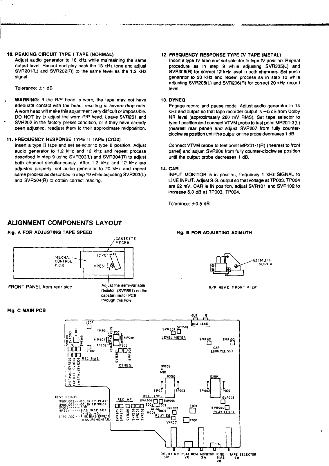
TAPE SPEED
Connect one output to Wow and Flutter Meter or Frequency
Counter, Play speedtest tape TEAC MlT-111
=
3 kHz or TEAC
MlT-211
=
3.15 kHz and adjust SVR851, for correct readlng
on Wow and Flutter Meter or FrequencyCounter.(See Fig. A)
Tolerance:
k
1
%
2.
AZIMUTH
Connect VWM's andlor Oscilloscope to outputs. Set tape
selector to normal and start playing Azimuth tape TEAC
MlT-113 or MTT-114. Rotate azlmuth screw for maximum
output andlor maximum and in phase on Osdlloscope. Reseal
adjustment screw with nail pollsh or similar (do not use
glue).(SeeFig. B)
3.
PLAYBACK EQ
MISADJUSTMENT IS NOT NEEDED UNLESS THE 'HEAD
HAS BEEN REPLACED OR REPAIR HAS BEEN DONE IN
HEADAMP CIRCUIT.
Play levellazimuthtape TEAC MTT-256 and adjust SVU001(L)
and SVR002(R) for identicaloutput at 31516300 Hz (MT-255)
or 25016300 Hz (M7T-256).
Tolerance: 20.5 dB
4.
PLAYBACK HIGH FREQUENCY
EQ
THIS ADJUSTMENT SHOULD BE DONE ONLY WHEN HEAD
HAS BEEN REPLACED.
Play frequency response tape TEAC MlT-258 or MTT-256U
and check playback level at
14
kHz.
Before adjust, cut the center of jumper leads E001(L) and
E002(A). Adjust by dlsconnectlng R001(L)
and
R002(R) If 14
kHz Is too low and connecting E001(L) and E002(R)
If
14 kHz
Is too high. Leave same component values In both channels.
Tolerance:
-+I
dB
5.
PLAYBACK LEVEL
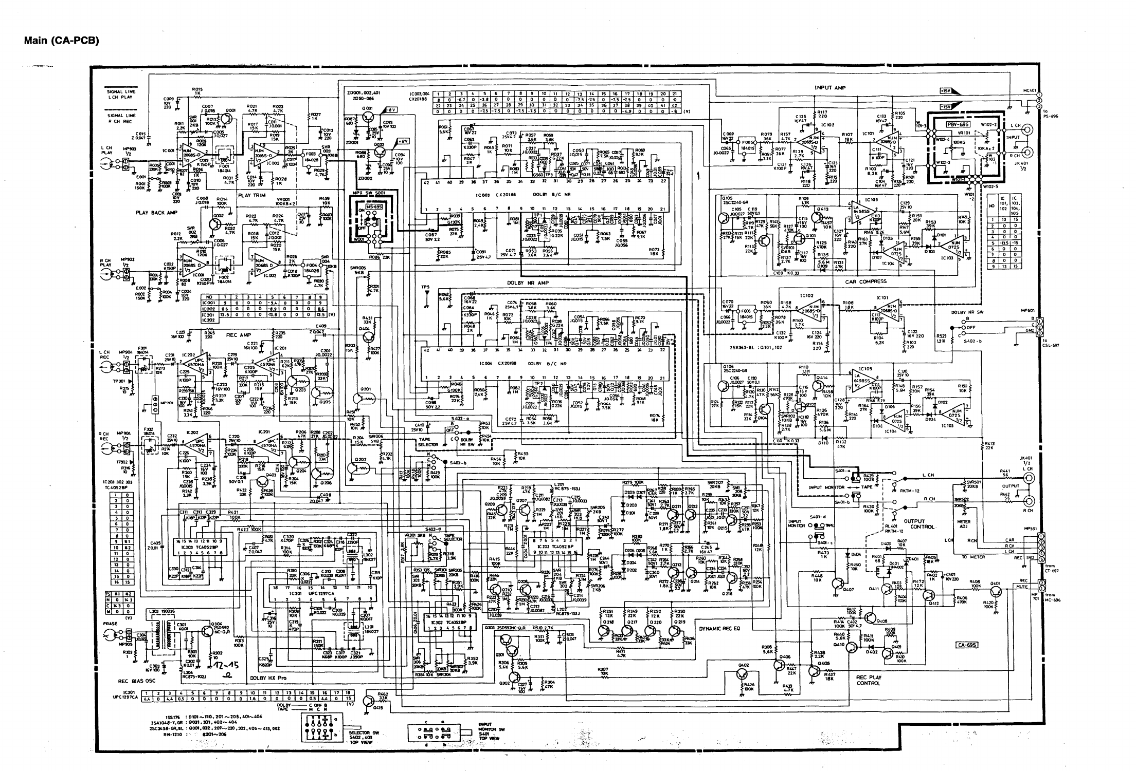
Connect VWM to testpoints. Play Dolby NR lev% tape TEAC
MTT-150 and adjust SVROO3(L) and SVROO4(R) for 245 mV
RMS at testpoint TP001(L) and TP002(R) on Main PCB.
Tolerance: k2.5 mV
RMS
Output shouldbe approximately505.mV RMS.
6.
METER LEVEL
Play Dolby NU level tape MlT-150 and adjust SVRSOl(L) and
SVR502(R) so that 0 dB LED'SJustturn on.
.I"
h
7.
BlAS TRAP
Inserta blank type
1
tape and start recording.Turn recordlevel
all the way down and set tape selector to type
lV
position.
Connect VNM's andlor oscilloscope probe to testpoint
MP201-3(L) and adjust F301 for minimum. Connect probe to
MP201-1 and adjust F302 for minlmum.
Tolerance: Less than 300 mV RMS.
8.
RECORD LEVEL
Set tape selector to .we
N
tape. Qonnect audio oscillator to
I
I
llne Inputs, tuh r&ord levela to maxlmum (clockwise). Adjust
audlo
oscillator
frequencyto
400
Hz andoutputqthat VTVM's
read 30
-
40 mV. (Use a condnlent referen-point on the
VNM's).
r
I
81
L
2
Reset tape countei~o0 anb release pause to start recording.
Recordfor approximately
5
seconds, rewindto0gntapewunter
andplay back while observingthe VTVM's. ~heh~'$should
Indicatethe same level as when the tape
was
recorde8~djust
SVRDO!5(L) and SVROO6(R)
If
neceseary and repeat the record
1play procedure untilthe readings are the same.
I
Tolerance: 20.5 dB from record level. Less than 0.5 dB
dlfferencs between channels.
9.
BlAS ADJUST TYPE
I
TAPE (NORMAL)
Set audlo generator to 1.2 kHz wlthout changing output level.
Reset
tape
counter to 0 and start recordlng. Afler 5 seconds
change audlo generator frequency to 12kHz (do not stop the
machlne or change levels) and wntlnue recordingfor another
5
seconds. Stop and rewind to 0 on
tape
counter. Play back
whlle obae~ingVNM's. There should
be
no
level difference
between the
1.2
kHz and the 12 kHz tone when played back.
If 12kHz Is
different
inlevelfor 1.2 kHz, adjust SVRSOl(L) and
SVR302(R) and repeat the record
I
play procedure until both
frequencies
play back at same level.
Tolerance:
f
0.5 dB
WARNING: Greater tolerance will grossly affect the Dolby NR
tracking and especially the Dolby C tracklng.
Reoord level (step
8)
should be checked and
if
necessary
adjusted.
www.freeservicemanuals.info
Worldwide electronic heritage manuals