CONGRATULATIONS!
Your
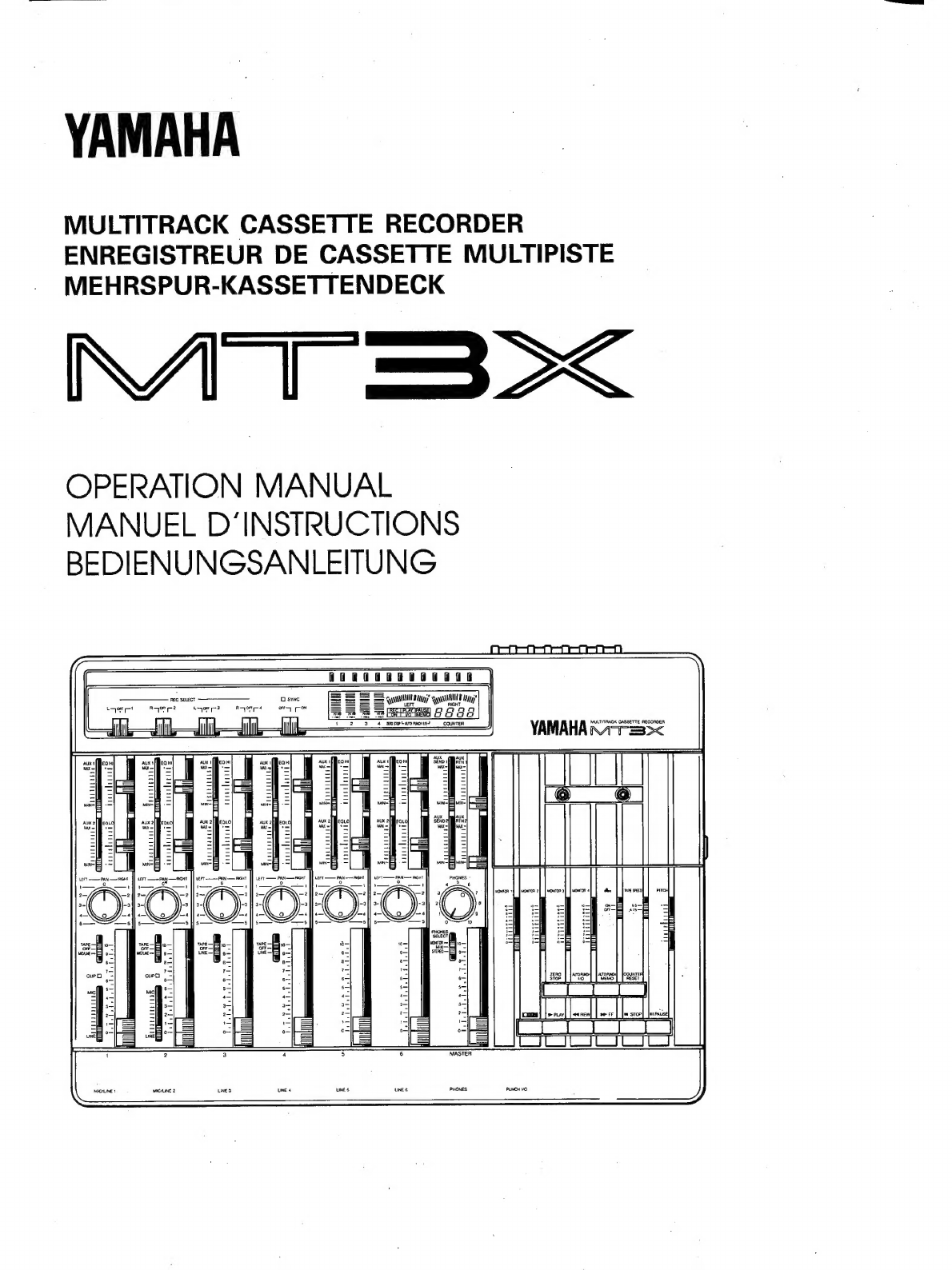
MT3X
Multitrack
Cassette
Recorder
is
a
fine
creative
tool
that
will
enable
you
to
work
with
sound
in
many
ways.
Whether
you
need
to
record
acoustic
instruments
or
voice
using
microphones,
electronic
instruments
and
sources
via
direct
line,
or
a
creative
blend
of
the
two,
the
MT3X
makes
the
process
of
building
up
your
own
sound
extraordinarily
smooth
and
simple.
You
can
simply
record
and
remix
four
tracks,
or
use
the
multitrack
“ping-pong”
recording
tech-
nique
to
individually
record
up
to
ten
independent
parts
—
adding
sound
layer
by
layer
until
you
create
exactly
the
ar-
rangement
and
texture
your
imagination
demands.
There’
s
even
a
sophisticated
auto
punch-inlout
feature
that
lets
you
re-record
a
section
of
a
previously
recorded
track
with
automated
convenience.
The
MT3X
is
just
as
easy
to
use
alone
or
with
a
band.
And,
because
it's
a
YAMAHA,
you
know
that
the
MT3X
will
give
you
the
very
finest
sound
quality
and
overall
performance
available.
In
order
to
make
use
of
the
MI3X'
s
many
features
and
obtain
maximum
performance,
we
urge
you
to
read
this
opera-
tion
manual
thoroughly
—
and
keep
it
in
a
safe
place
for
later
reference.
CONTENTS
PRECAUTIONS
7:
cox
tesa
a
oar
ee
PP
ERE
T
eege
2
BEFORE-
OPERATION
255555
м
a
ai
3
THE
CONTROLS
AND
CONNECTORS
.....................................
5
CONNECTION
EXAMPLES
22522
odin
eS
iG
au
ааа
Тијана
ва
наст
tin
DOR
ARN
A
13
THE
RECORDING
PROCESS
2.2
nun
ааа
а
Ya
d
ви
14
RECORDING
THE
FIRST
TRACK
........................................
15
STEP
1:
CHANNEL-TO-TRACK
ASSIGNMENT
........................
15
STEP
2:
MONITOR
SETUP
22:2
22mm
sale
ued
RC
ed
S
16
STEP
3:
SETTING
RECORDING
LEVELS
............................
17
STEPS
RECORD
Ar
рала
ie
wav
ees
EE
17
OVERDUBBING
........................
КОКТО
УКО
Р
УОК
СО
ГС
18
PING-PONG
RECORDING
.........................
ete
aim
уалы
ры
ыз
19
A
PING-PONG
RECORDING
EXAMPLE
.............................
20
MIXDOWN
ык
асық
ЫП
ны
He
WAN
ҚЫН
МАЯ
ҚБ
ра
21
USING
THE
AUX
SEND/RTN
LOOPS
................
E
Re
И
22
PUNCH-IN/OUT
RECORDING
...........:................................
23
Manual
Punch-in/out
Using
the
REC
SELECT
Switches
.................
23
Footswitch
Punch-in/out
...........................................
23
Automatic
Punch-in/out
..
:...
hh
hh
neas
24
MIDI
SYNC
OPERATION
.................
DE
жаза
Elte
25
MAINTENANCE
.......
e
IH]
hehehe
rus
BEER
UNE
26
SPECIFICATIONS
`...
27
BLOCK
DIAGRAM
...
не
EEN
28