NAD 6215 User guide

NAD •

1. Line IN
2. Line OUT
3. AC Po
we
r
Co
rd
2 1
NOIS£
REOUClION
SY
STEM
MAI"lJ
FAC
T
~£
O
UIllOE:R
LICENSE
FROM
OOlBV
l.woRATOIII
ES
UCENS....a
CORPOAAJION
-DOlB
Y-
AHO
THE
DOUIII.E.Q SVMBOl AAE
TRAOEMA.AXS
Of
OOLBV
L
A6ORATOOI'fS
lICENSI~
COFIPORAfION
MOO£
LNVM8IEfl 612S
3
'
,A
POWlA
RA
nN
G
25W
120V'220V740115060Hz _
S
IlRIA
LNUIAER
1. Po
we
r 9. Pause
2. Eject
10
. MPX Filler
3.
Tu
rns Counter
11
. Dolby NR"
4. Fast Forward
12
. Tape Selector
5. Rewind
13
.
Re
cord Level
6. Play 14. Reco
rd
i
ng
Level Display
7. Stop 15.
MI
C
8. Record
2 5 3 4
EJ
CT
I
NAD
I
SOM
Cassette
Deck
6
12
5
•
'"
0
....
~
FASHOfIWARO _
-
.....
c::=J
REWIND
''''
''
' .. c::=::::J
PL
"Y
MP
J(
F
IL
TER
--[] c::=::::J
STOP
- 0 c::::::J RECORD
I I
~
P.wSE
I
"---.I
1 6 7 8 9
10
2
MAOE
IN
J
APAN
"'"'
.
DOLBY
NR
0"
,,
11
l
CAUTION
~
.
TORE01JCE
Tl1IE
Rl$l<;0I' E
lfCmIC
SHOCK.
00
NOT
fI.EI"I()Y£
OOVER[OABAICI(j.
NO
US£P..SEfMCEABLE
PAAT!5
1ffS1OE.
REF
ER
SEIMCIHG TO QU.',UAEO
SfIfflCE
Pf:RSONtIEl
'Co
lby Noi
,e
Reduclion system
mlnul
eclured under license from
Dolby
lebo
ra
to
ti
es
lice
nsi
ng
Corporation. "
Oo
lby" and
the
double·O symbol ale Ifademstka
01
Oolby Laboralories.
14
,
•••••
,
REC.
201510
,.
202.'
·
d8
••••••
1
,
'''PIE
SELECTOR
RECORO
LE
VU
"'"
~"Q)~'
CD
~~
I
'--.J
12
13 15

REAR PANEL CONNECTIONS
1.
LINE
IN. The NAD
6125
is
intended to be connected
to Ihe Tape REC and PLAY (output and input) jacks
at
the rear
of any conventional stereo amplifier. Insert the phono plugs at
one end of a stereo connecting cable fully into the LINE
IN
sockets on the
6t25
. At the other end of the cable, insert the
plugs into the TAPE OUT
or
RECord jacks of the amplifier.
Use the color coding of the plugs to identify the channels;
for instance, if one of the plugs
at
each end of the cable
is
red,
connect the red plug to the R (right channel) socket of both the
amplifier and the NAD 6125.
2.
LINE
OUT.
To
play tapes, plug one end of a stereo
connecting cable into the NAD 6125's LINE OUT jacks, and
plug the other end into the TAPE
IN,
PLAY,
or MONitor input
jacks of the amplifier. Make sure that each plug is inserted
fully into its socket, and observe the color coding of the plugs
to ensure that the stereo channels are connected consistently.
3. AC POWER CORD. Connect the AC power cord
to
a
convenient wall outlet or to an "unswitched" AC convenience
outlet at the rear of your amplifier.
A
note
on
fnstallatlon. The excellent performance of
the NAD
6125
stereo tape recorder depends on
an
array of
precisely machined parts, fine bearings, smoothly polished
surfaces, sensitive detection of the weak magnetic fields
in
tape recordings, and amplification
of
very small signal volt-
ages. Consequently the recorder's performance can be
adversely aHected by external magnetic fields, electrical in-
terference,
vibration,
heat
,
mOisture,
or
chemical
fumes
.
Thus if
it
is
placed directly on top of a power amplifier, the
6125 may pick up a low-frequency hum from the amplifier's
power transformer.
If
you wish to install it next
to
an amplifier
on the same shelf, place the 6125 on the
le
ft so that its cas-
sette compartment will be located away from the amplifier.
The
6125
should not be placed on a loudspeaker or on a
television set (a source of strong magnetic fields as well as
vibration), nor in direct sunlight, nor very close to a steam
radiator, nor in a workshop where metal filings and chemicals
are found. The
6125
will function best at temperatures that are
comfortable for people, and it can be stacked or shelved with
the remaining components in your stereo system.
If you are located near a powerful television or radio
transmitter (including a citizen's band or short-wave unit) you
may pick up interference, especially when playing previously
recorded tapes. If you encounter this type of radio-frequency
interference, you may succeed in reducing it by experimenting
with the location and orientation of the recorder. Ifthe problem
perSists, your dealer or a service shop may be able to add
approved circuit modifications or extra internal shielding.
Connecting
two
recorders.
Some stereo amplifiers have
two sets of tape inpuVoutput jacks, with front-panel switching
~
e
lightning
flash
with
arrowhead
, wi
thin
an
eqUilateral
lriangle,
is
intended
to
alerl
the
user
of
the
presence
of
uninsulated
"
dangerous
voltage"
within
the
product's
enclo·
sure
;
that
may
be
at
sufficient
magnitude
to
constitute
a
risk
of
electric
shock
to
persons
.
3
to permit using either of two tape decks for recording or
playback and to permit copying tapes from one to the other.
If your amplifier has only one set of connections for a tape
recorder, it
is
still possible to use two recorders with it. The
most convenient and flexible method is to purchase an exter-
nal sWitch-box (Tandy Radio Shack #42-2105 or equivalent),
which will provide inpuVoutput connections for up to three
recorders and allow copying among them. The alternative
methods described below are less flexible, but they cost
less and yield equally good recordings.
Copying.
Connect the "copying" recorder (the machine
on which the new copy will be recorded) to the amplifier's
TAPE recording/playback jacks as described above. Then
connect to the amplifier's AUXiliary input a cable from the Line
Output jacks of the "source" recorder (the machine containing
the tape that you want to copy), and switch the amplifier's
Input Selector to AUX.
If an AUX input is not available, an alternative procedure
is
to disconnect the cable from the amplifier's tape RECord-
ing output, and connect the "source" recorder's Line Output
directly to the copying recorder's Line Input. With this con-
nection you must activate the copying recorder's RECORD
function in order to monitor the playback output of the
source machine.
Parallel
recording
.
Two
recorde
rs
can be wired in par-
allel to permit simultaneous recording on both. Obtain two "
V-
connector" adapters, each having two female phono sockets
and one male phono plug
(e
.g., Tandy Radio Shack #42-2436
or
equivalent). Plug one V-connector
in
lo
the Right channel
Tape RECording jack of the amplifier, and connect the Right
channel (red) plugs of two stereo cables
to
the V-connector's
two sockets. Plug the other V-connector into the Left channel
Tape REC jack, and connect the left-channel plugs (usually
black) of the two stereo cables
to
the V-connector's sockets.
Finally, at the opposite end of the two stereo cables, connect
to the Line Input jacks of the two recorders.
This hookup allows you to record freely on either ma-
chine, or simultaneously on both, but not to copy tapes from
one to the other.
NOTE: This method of parallel connection works well for
recording, but
not
for playback. If you use V-connectors
to
combine the Line Output signals from two tape decks, each
machine's output will tend to short-circuit the other's, yielding
a low playback level and possibly higher distortion. Only one
tape deck's Line Output signals can be fed
to
the amplifier's
Tape PLAY input jacks.
To
hear the playback from the second recorder, connect
its Line Output to the amplifier's AUX input. But observe this
precaution: never switch the amplifier's Input Selector to AUX
while recording on the machine whose output is connected
to
AUX; doing so would create a feedback oscillation that could
damage your loudspeakers.
~
e
exdamation
point
wi
thin
an
equilateral
triangle
is
i
ntended
to
alert
the
user
of
the
presence
of
important
operating
and
maintenance
(servicing)
instructions
in
the
literature
accompanying
the
appliance
.

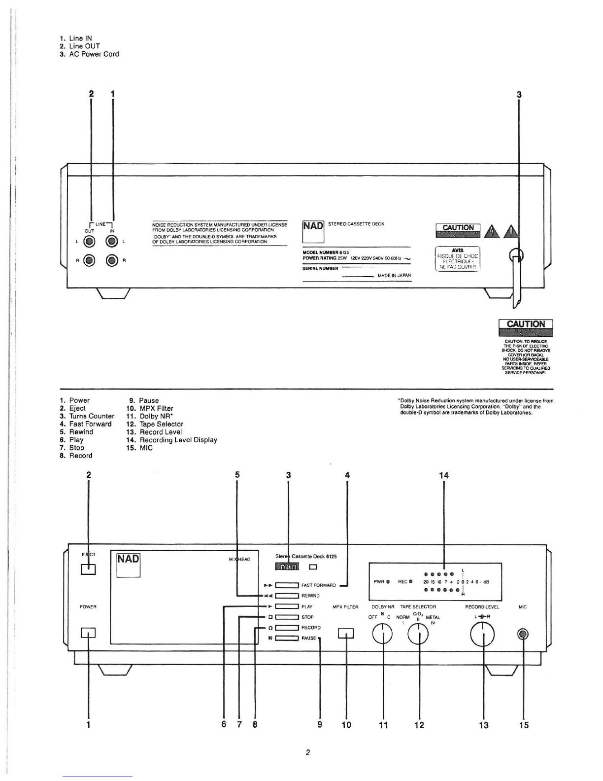
FRONT PANEL CONTROLS
1.
POWER. Press this switch to turn on the power
to
the
cassette deck. Press again and release to turn the power off,
A green LED at the left end of the recording level display
is
illuminated when the power
is
on.
The
capstan
drive
motor
runs
continuously
when
the
power is on.
To
prolong the life of the motor, switch the power
on only when the recorder
is
being used, and switch it off
when
you
are
listening
to
broadcasts
or
disc
records.
2.
EJECT. When this button
is
pressed, the door of the
cassette compartment swings open to allow a tape to be
inserted
or
removed, The tape cassette is held in a carrier
within the door assembly.
To
insert
a
tape
cassette,
remove
it
from
its
protective
box. Hold it so that its thick edge faces down, and so that the
full tape spool is at the left side of the cassette. Press the
EJECT button to open the door, slide the cassette into the
door's carrier slot, and push the door to close it.
NOTE: Always press STOP to disengage the tape trans·
port mechanism before pressing EJECT to open the door. (If
the machine is in the PLAY or RECORD mode the EJECT
button
is
automatically disabled for safety,)
3,
TURNS COUNTER.
Th
is
counter registers the turns of
the take·up spool in the cassette. Press the adjacent button
to
re-set the counter to 000
at
the beginning of a tape; then the
counter readings will provide a convenient method of identify·
ing the locations of selections on the tape. It will accumulate
a maximum count of approximately 450 over the length of a
C·60 tape, about 700 for a C·90, and about
gOO
for a C·120.
4.
FAST FORWARD/CUE. This button winds the tape
rapidly forward from the left to the right,
I.e"
from the
beginning toward the end of a recording,
If
the tape transport is
in
the STOP mode. disengaged
from the tape, then the button will latch down when pressed;
the tape will continue to fast·wi
nd
forward until you press
STOP or until the end of the tape is reached, At the end of the
tape the transport automatically disengages. returning to the
STOP mode after a brief delay, Since the record/playback
head
is
not
in
contact with the tape, no sound,
is
heard.
If
the tape transport is
in
the
PLAY
(or PAUSE) mode,
pressing the FAST FORWARD button activates the CUE
function, The tape winds forward only as long as you continue
to press fhe FAST FORWARD button in. The transporl
reo
mains engaged. automatically resuming PLAY (or PAUSE)
when you release the button. The heads remain in contact
with the tape,
so
any recorded material on the tape will be
heard as a loud, high'pitched squeal; this allows you easily to
find where recorded selections beg
in
and end, TURN DOWN
YOUR AMPLIFIER VOLUME CONTROL to prevent damage
to your speakers when using this cue mode,
5.
REWIND/REVIEW. This button winds the tape rapidly
from the right (the take·up spool) toward the left (onto the
supply spool),
If the tape transport is
in
the STOP mode, disengaged
from the tape, then the REWIND button will latch down when
pressed; the tape will continue to rewind rapidly until you
press STOP
or
until the beginning of the tape is reached,
Since the head is not in contact with the tape, no sound will
be heard,
If
the tape transport is
in
the PLAY (or PAUSE) mode,
pressing the REWIND button activates the REVIEW function.
The
tape winds rapidly back only as long as you continue to
press
the REWIND button
in.
The transport remains engaged,
automatically resuming PLAY (or PAUSE) when you release
the button, The heads remain in contact with the tape while
it
winds, so any recorded material on the tape will be heard as a
loud, high-pitched squeal; this allows you easily to find where
4
recorded selections begin and end, TURN DOWN YOUR
AMPLIFIER VOLUME CONTROL
to
prevent damage to your
speakers
when
using
this
cue
mode
.
6. PLAY. When this button
is
pressed, the tape
is
moved
from left to right at normal playing speed, the recorder's heads
are brought into contact with the tape, and the playback
circuits are activated, At the end
of
the tape, the transport
automatically stops and disengages itself from the tape,
7,
STOP.
This button stops the tape motion and disen-
gages all of the taoe transport functions (except PAUSE).
If
the machine was in PLAY or RECORD, pressing STOP causes
the heads to retract from the tape, allowing the door to be
opened by the EJECT button,
8. RECORD. Pressing this button activates the recording
circuits and also engages the transport to move the tape over
the heads so that a recording can be made. The red REC light
in the recording level display illuminates to indicate that the
NAD 6125 is in the recording mode. When recording, the
machine automatically erases any previous recording that may
be on the tape.
NOTE: In many tape recorders the REC button only
switches
on
the
recording
circuits
,
and
it
is
necessary
to
press
both REC and PLAY to engage the tape and make a record-
ing, But in the 6125 the single REC button commands the
entire
recording
process.
One-button
recording
is
convenient
,
but
it
means that if you accidently press REC instead of
PLAY
when you want
to
play back a tape, the machine will imme-
diately go into the recording mode and begin to erase the
recording that you wanted to hear,
To
prevent such acci·
dents, remove the erasure·prevention tabs (as described
later) from any recorded cassettes that you don't intend
to re·record on. With these tabs removed, the REC button
cannot be depressed.
To
stop recording and de·activate the recording circuits,
press
STOP.
To
stop recording briefly while leaving the recording
circuits activated, press PAUSE; then press and release
PAUSE again when you are ready
to
resume recording,
g,
PAUSE. Pressing this button once retracts the rubber
pinch roller from the capstan, thus halting the motion of the
tape
in
the PLAY and RECORD modes, while leaving the
playback
or
recording circuits active,
Pressing and releasing the PAUSE button a second time
provides
an
instant resumption of tape motion for playback or
recording.
NOTE: The PAUSE control
is
intended
to
stop the tape
motion temporarily,
To
stop the tape for more than a few
minutes, use the STOP button,
The PAUSE function can only be disengaged by pressing
and releasing the PAUSE button; unlike the other functions of
the tape transport, PAUSE does not automatically disengage
when STOP is pressed, If you forget that you have left the
PAUSE mode engaged, the Model
6125
may appear to be
malfunctioning when you try to record or play tapes, When
you press RECORD, for example, the red RECORD light w
ill
illuminate and the incoming signal will register on the record-
ing level display, but no signal will
be
recorded on the tape
until the PAUSE is released. (Then the changing number
in
the TURNS COUNTER will provide confirmation that the
tape
is
moving
.)
10
.
MPX
FILTER. This filter
is
intended for use when
you are making recordings with Dolby B noise reduction,
Any ultrasonic interference
in
the input signal during record·
ing, such as a multiplex pilot signal
in
an
FM
tuner, may cause
mistracking of the Dolby circuit and yield dull sound when t
he
recording
is
played back,
To
prevent this mistracking and
preserve a flat frequency response with Dolby
NR
, the MPX
filter should be switched ON (by pressing the button in) when-

ever a recording is made using Dolby B. The filler blocks fre·
quencies higher Ihan abcut
t5
kHz in the signal.
When playing previously recorded tapes, a very slight
extension of high·frequency bandwidlh may
be
obtained by
switching the MPX filter OFF (button out). But remember to
switch back in when making recordings with Dolby B.
If
you make any recordings with the Dolby NR switched
OFF,
the MPX filter is optional.
It
is also optional when you are
using Dolby C NR, since the Dolby C circuit contains some
ultrasonic
filtering
of
its
own
.
11.
DOLBY
NR.
The recorder
is
equipped with two types
of Dolby noise reduction. Dolby C provides the greatest
quieting of tape hiss, important when taping "live" musical
performances
or
wide·range recordings (digilal records, for
example). Dolby B provides optimum compatibility with older
tape recorders, portable and automobile stereo lape players,
and should also be used when playing most pre·recorded
music
cassettes
.
Each type of NR involves complementary processes
that are intended to match each other
in
both recording and
playback. Thus if a tape is recorded with Dolby C noise
reduction, it must also be played back with the Dolby C circuit
operating
in
order for the benefits of the Dolby system to be
obtained. Similarly, if Dolby B
is
used
in
recording it should
be used in playback
as
well.
To
avoid confusion, it is recom·
mended that you label each cassette "B" or "
c"
when it is
recorded, to indicate the type of noise reduction used.
Both types of Dolby NR operate by selectively compress·
ing the dynamic range of the middle and high frequencies in
the signal during recording. I.e. the circuit selectively boosts
the level of those middle·to·high frequency sounds that occur
at a naturally low level, so that these sounds are recorded on
the tape at a level substantially higher than the tape's own
hiss. Then,
in
playback, these signals are expanded back to
their original dynamic range; the quiet middle and high fre-
quency sounds that were boosted are finalty cut back down
to their original levels, and the tape's hiss is reduced
at
the
same
time
.
Dolby
Band
C differ in the amount of complementary
boostlcut that they provide, and in its frequency distribution.
Dolby B operates mainly at high frequencies and suppresses
tape hiss by a maximum of
10
dB. Dolby C operates at both
middle and high frequencies and reduces hiss by as much as
20 dB. The two Dolby systems are
not
interchangeabl~.
If you
record with Dolby B and play back with Dolby C (or vice versa)
the tonal balance of Ihe musical sound will be substantially
altered.
Also, any brightening or dulling of the sound that
is
caused by a mismatch between the recorder and the tape will
produce mistracking in Ihe Dolby circuit and yield an exag·
gerated brightening or dulling of Ihe playback sound. So when
Ihe Dolby circuits are to be used,
it
is
especially
importanllhat
the TAPE SELECTOR be correctly set
to
match Ihe tape (both
:in recording and in playback).
12.
TAPE SELECTOR. This switch selects the correcl
bias (for recording) and equalization (for playback), for each of
three standard types of cassette lape. Whenever you record
or
playa
tape, this switch musl be set to match the tape. If you
are not careful aboul this, the clarity and lanai balance of your
recordings will vary a great deal, especially when Dolby noise
reduction is used.
f.
Normal. The largest variety of casselIe lapes are
intended for use wilh Ihe NORMAL setting
of
the TAPE
SELECTOR. Look
al
the cassette package for a statement of
"normal bias"
or
"120
fLsec
" equalization.
In
general, tapes
described as "ferric oxide," "low noise," or having the Roman
numeral f in their deSignation, are intended for the NORMAL
selting.
5
It.
Cr02'
The cr02setting is intended for tapes employing
chromium dioxide or the "chrome·equivalenl" cobalt·doped
high·bias ferric oxide. Usually these are identified as requiri
ng
"high bias," "70
fLsec
" equalization, or have Ihe Roman
numeral
II
in their designation.
fV.
Metal. The Metal selling should be used with metal·
particle tapes, which may be labeled with Ihe Roman nu·
merallV.
While the TAPE SELECTOR switch provides Ihe large
changes
in
recording bias and playback equalization that are
needed to accommodate the Ihree standard classes of tape,
there
are
significant
brand-la-brand
differences
in
sensitivity
and frequency response among tapes
within
each group.
If
you wish, you can use the
6125
10
make recordings on
any brand and type of tape, using any setting of Ihe TAPE
SELECTOR, withoul harming either the recorder
or
the tapes.
And by experimenting with vanous tapes you may exploit their
different tonal qualities to produce pleasing
results-using
the
recorder
,
in
effect,
as
a
tone
control.
But the basic purpose of a high·fidelity tape recorder
is
to
provide
an
exact replica of the original sound, capturing and
preserving it for later playback. This is what the NAD
6125
is
designed to do.
If
you want to make the most accurate
recordings, you must use tapes similar to those used
in
the
factory for calibrating the recorder's circuits. This
is
especially
important when Dolby noise reduction
is
used, because any
departure from accurate high·frequency response in a record·
ing (due to a mismatch between recorder and tape) will cause
decoding errors in the Dolby circuit during
playback-and
this,
in
turn,
will
cause
larger
errors
in
frequency
response
,
making
the sound excessively bright
or
dull.
For information on tapes that are compatible with the NAD
6125,
see your NAD dealer.
13. RECORDfNG LEVEL. This knob controls the strength
of the audio signal fed to the tape when a recording
is
being
made. The signal strength is shown on the recording level
display, above.
The RECORD LEVEL control
is
actualty two co·axial
controls (one for each stereo channel), friction·coupled so that
they normally rotate together.
It
is possible
to
alter the stereo
balance by adjusting the two controls differently. The left chan·
nel is controlled by the central part of the knob, while the right
channel
is
controlled by the outer part (the sleeve around the
circumference of the knob).
14. RECORDING LEVEL
Of
SPLAY. This dual row of
LEOs displays the peak level of the signal in each channel
during recording
or
playback. The LEOs ranging from -20 dB
to 0 dB are green and indicate normal recording levels. The
+2, +4, and +6 dB LEOs are
red
and indicate the maximum
permissible levels.
In
general, you should adjust the recording level so that
the loudest portions of the music are recorded at levels be·
tween - 4 and +2 on the display. With music that spans a
large range of volume levels, such
as
a symphony, this may
mean that the quiet portions of the music will be recorded at
indicated levels of -20 dB or even lower (with no LEOs
illuminated); this
is
normal.
To
learn how to sel optimum recording levels, the follow·
ing experiment is recommended. Select a typical recording of
music
and
record
an
excerpt
from
it
several
times
in
succes-
Sion
, setting the recording level progressively higher each
time. For example set the maximum peak level
at
about
-
10
dB the first time, and repeat
it
at about -
4,
at
0, at +
4,
and finally at over +6 dB. Then play back the recordings and
lislen for symptoms of tape saturation
in
the sound. (Adjust
your amplifier's volume control
to
compensate for the different
loudness levels of the sample recordings, so that you can
focus your attention on the quality of the sound without being

distracted by volume differences.)
At a peak level of -
10
dB the sound should be clear,
open, and detailed, but the background of tape hiss may be
bothersome. At peak levels of +4 or +6 dB you probably will
begin to hear the effects of tape saturation: boomier bass,
mushy midrange, or dull treble. Also, tape saturation will
reduce the peak levels: a signal that was recorded at
+4 dB may pl
ay
back at only 0 or +2 dB.
The optimum recording level
is
the highest level that you
can use
(In
order to minimize audible hiss
in
playback), but
wIthout encountering audible symptoms of tape saturation. As
a general rule, you can use higher recording levels for brief
transient sounds (such as drumbeats) than for continuous,
sustained tones (e.g
.,
the singing voice). And you can use
higher recording levels for sounds whose energy
is
concen-
trated at midrange frequencies (e.g., spoken voice) than for
sounds having a great deal of energy at
very
high frequencies
(cymbals, bells, harpsichord) or at very low frequencies (pipe
organ, bass drum). With the latter, the peak level usually
should be set no higher than about -2 dB.
When in doubt it usually is best to err on the conservative
side, sacrificing a bit of potential signal-to-noise ratio in favor
of a little extra undistorted headroom for musical peaks. With
Dolby C noise reduction to minimize any audible tape hiss,
you can afford to under-record slightly; and this practice will
help
to
ensure that you preserve all of the air, brilliance, and
detail in the original sound.
You
may find that, in order to achieve peak recording
levels near 0 dB, you have to set the RECORD LEVEL control
to
a different position for recording
FM
broadcasts than when
recording from phonograph records. This
is
normal.
15
, MIC. The microphone socket will accept a signal from
any
conventional
microphone
whose
cable
terminates
in
a
%"
(6mm) phone plug. If your microphone terminates in another
type
of
connector, plug adapters can be used to convert to
the standard phone plug. Any type of microphone, with any
Impedance
,
may
be
used;
but
a
low
or
medium
impedance
mike
is
recommended
.
The microphone signal is recorded equally in both chan-
nels, as a monophonic signal
in
the center
of
the stereo slage.
If you wish
to
make stereo recordings with two (or more)
microphones, connect the mikes to a microphone preamp!
mixer and then connect the output of the mixerto the
LINE
IN
jacks.
When a microphone plug is inserted into the MIC socket,
the input signal from the LINE
IN
jacks is automatically dis-
connected. (If a loud signal
is
present
at
the LINE
IN
jacks, a
faint trace
of
it may still leak into the microphone input.
So
if
you are making a critical recording with a microphone, the
Signal cables should be disconnected from the LINE
IN
jacks
when the mike
is
used.
In
order
to
resume
recording
from
a
tuner
or
amplifier
via
the LINE inputs, the microphone plug must be removed from
the MIC socket.
When recording a spoken voice, the most natural voice
quality will usually be obtained by placing the microphone at
a distance of
15
to
30
cm
(6
to
12
inches) from the mouth.
Holding the mike
very
close
to
the mouth,
in
the manner of
rock singers, will produce poor sound with many microphones.
CAUTION: When the Model 6125 is in the RECORD
mode, the signal being recorded also appears at the LINE
OUT jacks and so is fed to your amplifier for monitoring. If
you record with a microphone in the same room, its signal will
then be amplified and reproduced
by
your loudspeakers. The
resulting "feedback" howl could damage the speakers.
To
prevent this possibility, whenever you record with a micro-
phone you should turn off your amplifier or switch it so that
the tape recorder'S output cannot be amplified.
6
OPERATING PROCEDURES AND
HI
NT
S
To
Play
Recorded
Tapes
1.
Before inserting a cassette, check it to be sure that the
tape is straight and taut where it is exposed at the thick edge
of the cassette. If necessary, insert a pencil into either tape
spool and manually wind the tape until any slack
is
taken
up
.
2. Press the EJECT button
to
open the door. Insert the
cassette with the thick edge down and with the
fu
ll
spool of
tape at the left side. Push the door closed.
3. If the tape has been in storage for several months, it
may be necessary
to
loosen the tape pack
by
fast-winding the
tape. (Press FAST FORWARD
to
wind the tape through its
entire length, then REWIND to return to the beginning.) If the
tape sticks and will not fast-wind, hold the cassette in the palm
of your hand and slap it face-down on a tabletop.
CAUTION:
Str
ike only the flal face of the cassette against
the table. If you strike the edge of the cassette against a hard
surface, you could break it.
4.
Set the TAPE SELECTOR to match the type
of
tape
being played. For pre-recorded music cassettes this
is
usually
NORMAL.
In
the case of chromium dioxide tapes, examine the
package:
if
"
120
microsecond" equalization
is
specified, use
NORMAL; if not, set the switch to Cr02'
5. Set the Dolby NR switch to match the noise-reduction
system that was used to record the tape.
If
the tape was
recorded on the NAD 6125 using Dolby C (or on another tape
deck equipped with Dolby
C)
, set the Dolby NR switch
to
C for
playback. If the tape was recorded on a machine equipped
only with Dolby B, or is a commercially pre-recorded music
cassette made with Dolby B encoding, set the Dolby
NR
switch to B.
If the tape was recorded with
no
nOise-reduction, switch
the Dolby
OFF.
Also, some older pre-recorded music cas-
settes made with Dolby B may have been so poorly processed
that they sound dull with normal Dolby B playback decoding.
In
such cases you may obtain better sound by switching the
Dolby OFF during playback and then using your amplifier's
tone controls to obtain the most realistic tonal balance.
If the tape was recorded with DBX noise reduction, switch
the Dolby OFF and connect the tape deck to an external
DBX
If
noise-reduction decoder for playback.
Remember to switch the Dolby NR back to B or C when
recording your own tapes.
6.
Switch OFF the MPX filter (button out) to obtain the
most extended high-frequency response during playback. (But
remember to switch the filter back
on
when making recordings
with Dolby B.)
7.
Press
PLAY.
To
Make a
Recording
1.
Before inserting a cassette, check it to
be
sure that the
tape
is
straight and taut where
it
is exposed at the thick edge
of the cassette. If it is not, manually wind the tape to take up
the slack.
2. Press the EJECT button to open the door. Insert a
blank cassette with the thick edge down and with side 1 (or
A)
faCing
you. Through the window
in
the cassette you should
see a full spool of tape on the left side.
3. If the tape is new and has just been unwrapped for the
fi
rst time, the tape pack may have developed some friction
during the period of storage since
it
left the factory.
To
loosen
the tape pack, press FAST FORWARD to wind the tape
through its entire length,then press REWIND to return to
the beginning.
4.
Set the turns counter to 000. Then, as you make the
recording, you can take note of the counter reading corre-
sponding
to
each recorded selection.

i I
5. Set the TAPE SELECTOR switch
to
match Ihe lape thai
you are using.
6. Sel the Dolby
NR
switch
10
C (for maximum quieting of
background tape hiss), unless you are recording a tape for
playback on a portab
le
or other machine that has only Dolby
B or no noise reduction at all. When recording with Dolby B,
switch Ihe MPX filter ON (button in).
Z
In
order
10
determine the optimum recording setting of
the RECORD LEVEL control, it is desirable to activate the
recording circuils without actually depositing a recording on
the tape.
To
do this, press PAUSE and then REC. Observe the
recording level display while setting the RECORD LEVEL
control so Ihat the highest levels
in
Ihe music regisler are at
approximately 0 dB.
When you are ready to proceed with the recording, press
and release the PAUSE button to start the tape moving. (Its
motion will
be
confirmed by the gradual
ly
changing reading of
Ihe turns counter.) Since Ihe recordi
ng
circuits have already
been aclivated, Ihere
is
no need to press REC again.
8.
In
most cassettes the first few inches of tape
al
either
end is a "leader" with no magnetic coating. Remember
to
let
the tape advance by several counts (on the turns counter)
before beginning the recording.
9.
To
interrupt the recording al any point, press PAUSE;
this will stop the lape while leaving the recording circuits and
recording level display active.
To
resume recording, press and
release PAUSE again.
10
. At the end of the recordi
ng
session, press
STOP.
If you want
10
continue recording on the other side of the
cassette, press FAST FORWARD to advance the tape
to
the
end
of
side
A;
remove
the
cassette
,
turn
it
over,
and
insert
it
with side B facing you. Press REC to resume recording.
To
Erase
Tapes. The recorder automatically erases pre-
vious
recordings
as
a
fresh
recording
is
made
.
To
erase
an
entire tape, simply turn down the RECORD LEVEL control
to minimum, press REC, and record over the full length
of the tape.
Prevention
of
Accldentaf Erasure. Every cassette
is
equipped with two plastic tabs in cutaway holes in the top
(thin) edge of the cassette. One tape is for side A and the
other for side B; when you hold the casselle so that side
A faces you, its tab
is
on the top of the cassette near the
left end.
These tabs engage a safety interlock in the recorder that
permits Ihe recording and erasing circuits to be activated. If
you think that you may wish to erase and re-use a cassette in
the future, do not disturb the tabs. But if you have made a
valuable recording that you want
to
keep, you can safeguard
it against any possibility of accidental over-recording and
erasure by breaking off the corresponding tab. (If the valued
recording occupies both sides of the cassette, break off
both tabs.)
If you change your mind and decide to re-record over
the tape after having removed Ihe erasure-prevenlion tabs,
simply cover the cutout wilh a piece of cellophane or olher
adhesive tape.
Maintenance. The bearings and olher moving parts
in
this recorder are assembled with long-life lubricants and
requ
ir
e
no
periodic
maintenance.
But
in
order
to
preserve
the
NAD
6125
's high level of performance, all surfaces thai the
tape comes in contacl with must be maintained free of dirt
and free of magnetism.
7
Regular
cleaning
is
the
primary
requirement.
Dirt
particles
smaller than a Iwo-Ihousandlh of an inch
(0
.
01
mm),
if
lodged
on the polished surface of Ihe record/play head, can cause a
large falloff
in
high-frequency response. One easy way
10
clean the heads on a daily basis is to use a head-cleaning
cassette (a cassette that contains a lextured paper tape
inslead of magnelic lape
).
Play the cleaning casselle for
several
seconds
before
each
recording
or
playback
session,
and as Ihe cleaning tape rubs over the heads it will remove
accumulated parlicles of dust and tape oxide.
At longer
intervals-weekly
or month
ly
depending on how
heavily you use the
machine-a
liquid solvent or spray should
be used to remove lape oxides
or
sticky residue deposited on
Ihe heads, capstan, and pinch roller. Tape head cleaning
sprays and fluids are available from your hi-fi dealer and from
other
sources
.We
recommend
a
solution
whose
active
ingre-
dient is either alcohol (denatured or "isopropyl") or Freon
(a
fluorinated hydrocarbon compound); some head cleaners con-
tain both. If you use isopropyl alcohol, check to be sure that
the solution does not contain any unwanted oily substances
such as Lanolin.
To
clean the tape transport, remove any casselle from
the machine. Use the fluid or spray
to
moisten a cotton swab,
then use the moist swab to scrub the black erase head, the
silver-colored record/play head, the steel capstan, and the
black rubber pinch roller.
The door of the cassette compartment can be removed to
provide easier access to the heads for cleaning and demag-
netizing. The door
is
actually
in
two parts: the framework that
holds the cassette, and an extenor plastiC trim panel contain-
ing the NAD logo and the transparent window. Press EJECT to
swing the door open; remove any casselle, and press firmly
upward
on
the exterior surface of the door
to
detach
it
from the
cassette holder. (Your NAD dealer can show you how to do
this
.)
To
re-install the door panel, align its fastening clips with
the retainers on the casselle holder, and slide the panel down
into place.
During months of regular use the heads and sleel capslan
may acquire a magnelic charge that will add hiss to all lapes
played or recorded
in
the machine. Approximately once a
year Ih
is
charge should be removed by
us
i
ng
a head
de
-magnetizer.
Before using the de-magnetizer, switch off the power to
the recorder. Open the cassette compartment,
and
remove its
door panel. Take away any cassettes from the vicinity. Hold
the de-magnetizer away from the machine (to protect the
recorder from the de-magnetizer's turn-on surge); plug in the
de-magnetizer, turn
it
on, and then slowly pass
it
s probe tip
over the heads and capstan. (The probe tip may
be
allowed
to
touch the heads and
capstan-but
only if its metal surface
is
covered with a plastiC sleeve or wrapped with plastic tape to
prevent
it
from scratching the heads.) Move the probe tip
slowly out of the casselle compartment, and move the de-
magnetizer at least a meter (3 feet) away from the recorder
before switching it off. If you aCCidentally switch off the
de-magnetizer while its probe tip
is
within the cassette
compartment, the entire de-magnetizing procedure must
be repeated.
If you prefer not
to
do it yourself, you may have a
complete annual cleaning and de-magnetizing service done
for your recorder by your NAD dealer or by
an
independent
service shop. At the same time, you may have the recorder's
internal bias and Dolby circuit adjustments calibrated to match
the particular brand and type of tape that you prefer to use.

ELECTRONICS
LONDON/BOSTON
Table of contents
Other NAD Cassette Player manuals