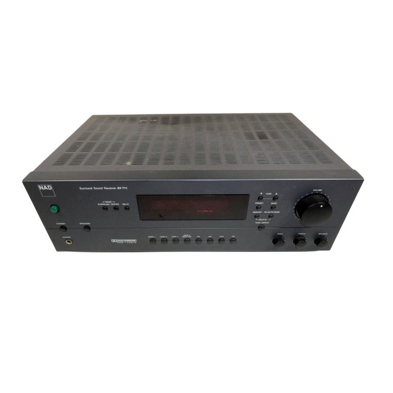
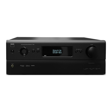
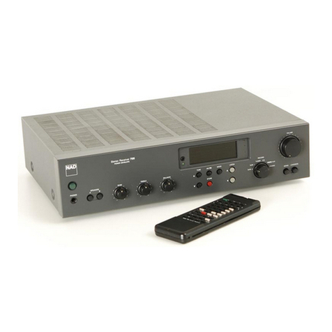
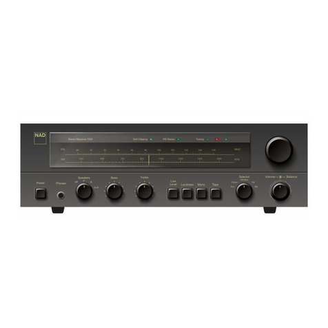
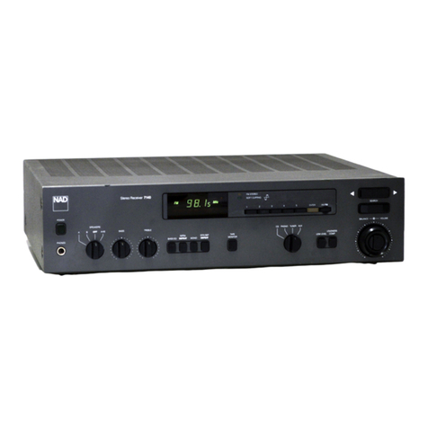
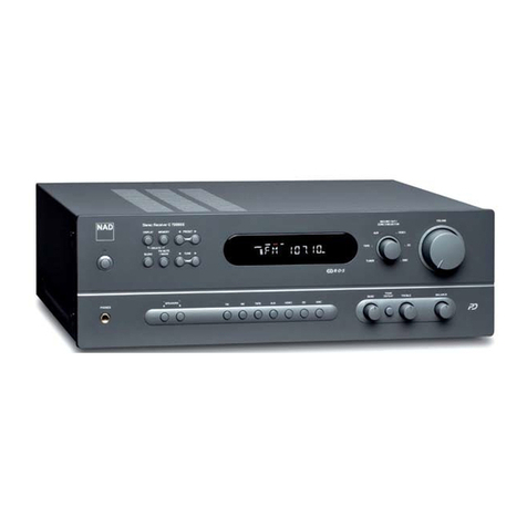
NAD 7130 User guide

www.SteamPoweredRadio.Com
ENGLISH
-
PAGE
3-11
FRAN<;AIS
-
PAGE
12-19
DEUTSCH
-
SEITE
20-27
NOTE: Some NAD components are equipped with
dual or multi-voltage transformers (which is indicated on the
back panel).
If
you wish to change the voltage, please bring
your unit
to
an
authorized NAO service technician for
in
-
ternal conversion.
ATTENTION: Quelques pieces NAD sont munies
de transformateurs adouble ou amulti-voltage (indique
au
panneau arriere).
Si
vous voulez changer
le
voltage,
veuillez apporter votre appareil
au
fournisseur de NAD
pour
le
transformer.
ZUR BEACHTUNG: Einige NAD Gerat~ sind mit Um-
schaltern fur unterschiedliche Eingangsspannungen aus-
gerustet (Ein Vermerk auf der Ruckseite weist darauf hin).
Aptierung, wenn notwendig,
muB
von einem qualifi-
zierten Techniker
in
einer
NAD
Servicestation vorgenom-
men werden.

www.SteamPoweredRadio.Com
REAR PANEL
1. AC Lme Cord
2.
AC
Ou11els
.
3.
Speakers A.
4.
Speakers
8.
5.
Anlenna
Te
rminals
S.
AM
Rod Antenna
7.
Phono Ground
8.
Phono lnpul.
7
INPUT
9.
MM
MC Selector.
10. CO Input
11
.
Au,i:
Input.
12.
Tape
Rec Play.
13.
Preamp Out.
Ma
in
In
14. Solt Clipping
15. Speaker Impedance
6
_L
MC
• MM
LE PANNEAU ARAIERE
1. Cordon d'ahmentat1on
9.
Selecleur
de
phonolecleur
2.
Prises
CA
10. Entree lecleur
de
d1sque
compact
3.
Ence1ntes A
11
. Entree
au1Ulia1re
4. Ence1ntes B 12. Entree Sortie magnelophone
5. Bornes d'antenne 13.
Sol't1e
de preamphl1cahon
6.
Antenne AM 14. EcrE!tage en douceur
7.
Masse phonolecteur
15.
Impedance
8.
Entree phono
5 4
ANT
NNA
AM
(.,
300
11
300
ll
1__,M----~
A0CKSE
ITE
1. Netzkabel
9.
MM MC
Um
schaller
2. Sekundar-Steckdosen 10. CO-E,ngang
3.
Anschlusse tu, Laulsprechergruppe A
11
. Reserve E,ngang
4.
Anschlusse lur LautsprechergrupPf' B 12. Tonbandgerat E1ngang Ausgang
5.
Anlennen-Auschlusse 13. Vorverstarker•Ausgang Endversta1ker-E1ngang
6.
M!ltelwellen (AM)-Femtantenne 14. lmpulsbegrenzungs-Schalter
7. Masseanschluf! fur Platlenspteler
15.
Lau1sprecner1mpedanz-Schalter
8.
Pla1tensp
1ele
r-Emgang
3
15
2
TCHEO
NAD
ELECTRONICS, INC.
BOSTON,:LONOON/TOKYO
L
PHONO
)(
OU
CREC!
IN
LAYl
OUT
M N
IN
O
N•
O'
'f
SOfl
C
NG
[gJ
8
FRONT
PANEL
1. Power.
2. PhOnes.
3.
Speaker Seleclor
4.
Bass.
5.
Treble
6.
Bas
s
EO
.
7. lnlrason1c Filler Defeat
8. Mono
9. Oyn Sep Delea!.
10.
Tape
Monitor
11
. Input Selector.
1
PHONE
S
2
9 10
11
12
13
LE PANNEAU AVANT
12. Low Level 1. Ahmenlahon
13.
Loudness Compensation.
2.
Casque d'
E!Coute
14
. Volume Balance 3. Setecteur d encemtes
15. Tuning Display. 4. Graves
16. Status lnclicators 5. A,gus
17. Tuning Pre-sets 6. Bass Eq
18.
Memory
Enter 7.
F1!1re
1nlrason1que
19.
AM FM 8. Mono
20. Up Down Tuning 9. Separation dynam1que
21
. Search Mode (FM only) 10. Commutateur de surveillance de bande
11. S8lecteur d'entree
15
Stereo Rece,ver
713
0
SPEAKERS
B OFF
A+B
3
4
fREBl
E
5
BASS INFRA DYN
SEP
EO
DE
F£
Al
MONO DEFEAT
6 7 8 9
14
12.
..
Low level "
13
. Commutateur de contour sonore
14. Volume
EQu1hbrage
15. All1chage de la heQuence d accord
16. Temoms
17.
Tou
ches de p,eselect
1on
18.
Touche
de
memo1re
19.
FM AM
20.
Syn1omsat1on
eleclronique
21
. Synton1sat1on au!omat1Que
16 17
FM
STEREO
<;Ol
lCl
lf'f'lrW,
ET
LES
CO
NSEQU
ENCES
GRAVES
QUI
POURRAIENT
EN
RESULTER. NE
TENTEZ
PAS D'
OUVRIA
LAPPAAEIL
ET DE
TOUCHER
AUX
CO
M
POSA
NTS INT
EANES
SANS LA
PRESENCE
D'
UNE
PERSONNE
OUALIFIEE
FRONTSEITE
1. Netzschalter
2.
KoplhOrer-Anschluf!
3.
Laulsprecher-Wahlschalter
4. Baf!sleller
5.
HOhens1eller
6.
BaB Equahzer-Schalter
7. $chatter tur lnfraschall-F,ner
8. Mono Slereo-Schalter
9. Dynam1sche Rauschm1nderung
10.
Vor
Uber Band-Schaller
11
. Emgangs-Wahlschalter
18 19
CAUTION
TO
REDUCE
THE RISK OF ELECTRIC
SHOCK
DO NOT REMOVE
COVER
(OR BACK)
NO
USER-SERVICEABLE
PARTS INSIDE REFER
SE
RVICING TO
QUALIFIED
SERVICE
PERSONNEL
1
12. Schalter lur Lautstarkeabsenkung
13. Geh0mcht1ge Lautstarke-EmsteUung
14. Lautstarke Balance-Sleller
15. Abst1mmanze1ge
16. Anzeigen lur Betnebszustcinde
17.
Sta11ons1asten
.
18.
E,ngabebere11schah
fur
Stahons1as1enspe1cher
19.
Weltenbere1chsschalter fur
UKW
M1ltetwelle
20. W
1ppe
zur Frequenzemste!lung
21
. Suchlaul. nur UKW.
20
21
◄
►
►■◄
c::::::J
CJCJCJ
CJ
TAPE
MONITOR
10
2
CD
PHONO
rLJNER AUX
11
BALANCE
--i}-
VOLUME
LOW
LOUDNESS
LEVEL C
OMP
12
13
14

www.SteamPoweredRadio.Com
ENGLISH
A NOTE ON INSTALLATION
This unit may be installed on any sturdy, level surface.
Since its power transformer generates a magnetic hum field
of moderate strength, a turntable (especially one with a
moving-coil pickup cartridge) should not be located directly
to the left of the amplifier nor directly above
it.
The amplifier generates a modest amount of heat and
thus requires some ventilation.
Do
not place
it
on a rug or
other soft surface that
it
could sink into, obstructing the air
inlets on its bottom. And be careful not to obstruct the air
outlet grille on the top cover.
CAUTION:
To
prevent a fire or shock hazard, do not
permit liquid or moisture to enter the amplifier. If liquid
is
accidentally spilled on it, immediately shut off its power and
unplug its AC power cord. Allow sufficient time for complete
evaporation to occur before operating the amplifier again. (If
the liquid
is
anything but water and/or alcohol, the amplifier
should be examined by a service technician before power
is
applied to
it
.)
Do
not open the amplifier, or attempt to modify or repair
it yourself. Refer all servicing to a qualified technician.
CAUTION: TO PREVENT ELECTRIC SHOCK
DO
NOT USE
THIS
(POLARIZED)
PLUG WITH AN EXTENSION CORD, RECEPTACLE
OR
OTHER OUTLET UNLESS THE
BLADES CAN
BE
FULLY INSERTED TO PREVENT BLADE EXPOSURE.
ATTENTION: POUR PREVENIR LES CHOCS ELECTRIQUES NE
PAS
UTILISER
CETTE FICHE POLARISEE
AVEC
UN PROLONGATEUR, UNE PRISE
DE
COURANT
OU
UNE AUTRE SORTIE
DE
COURANT, SAUF SI LES
LAMES
PEUVENT ETRE
INSEREES A FOND SANS LAISSER AUCUNE PARTIE A DECOUVERT.
Th
lig. h. tning flash with arrowhead. with
in
an
equilater
al
angle. 1s intended
to
alert the user of the presence of
ninsulated "dangerous voltage
··
wi
th
in
th
e product's enclo-
sure: that may be of sufficient magnitude to constitute a
risk of electric shock to persons.
3
REAR PANEL CONNECTIONS
1.
AC LINE CORD
Plug the AC line cord into a "live" wall socket.
2. AC OUTLETS (not
in
U.K. model)
The AC power line cords of other stereo compo-
nents may be plugged into these accessory outlets. The
SWITCHED outlet.
is
intended for all-electronic products
(e.g
.,
a tuner, equalizer, or other signal processor), and will
be switched on and off by the amplifier's main POWER
button. The UNSWITCHED outlet should be used to power
products involving mechanical operations
(e
.g., a turntable
or tape deck); such products should
be
switched on and off
with their own power switches.
The UNSWITCHED outlet can also
be
used to power
any device containing a clock timer, or a digital tuner that
requires uninterrupted AC power to maintain station tuning
information stored
in
its memory.
3. SPEAKERS A
If the wire connecting each loudspeaker will be less than
6 meters (20 feet) long, then connections should be made
using 18-gauge wire such as common lamp cord ("zip" cord),
available from hardware and electrical-supply stores
in
either
white, black, or brown insulation.
If the wiring to the speakers will be longer than 6 meters,
heavier 16-gauge or 14-gauge wire
is
preferred. Heavy-duty
wiring
is
especially desirable if you are using speakers of
low impedance.
The loudspeaker terminals are heavy duty binding posts.
Each binding post consists of a threaded metal shaft and a
red or black screw-on bushing. Connections may be made
in
either of two ways.
(1)
A small horizontal hole through the lower end of
the threaded shaft accepts bared wires up to
16
gauge
in
thickness.
To
make connections, separate the two conductors
in
each speaker cable. Strip off about a half-inch
(1
cm) of
insulation from each, and
in
each conductor twist the exposed
wire strands together. Unscrew the bushing a few turns to
expose the hole, insert the bare speaker wire into the hole
in
the metal shaft, and screw the bushing down tight.
(2)
A standard spring-type banana plug may be inserted
axially into the top of each binding post. The binding posts
have the
¾-
inch
(19
mm) spacing required to accept stan-
dard dual-banana plugs. Purchase dual-banana plugs and
install them on your speaker cables (or purchase speaker
wires with dual-banana plugs already attached), and plug
the dual-banana connectors into the binding-post terminals.
Phasing. Stereo speakers should operate
in
phase
with each other
in
order to yield a good stereo image and
to
reinforce rather than cancel each other's output at low
frequencies.
If
your speakers are easily moved, their phasing
can easily be checked. Make the connections to both speak-
ers, place the speakers face-to-face only a few inches apart,
play some music, and listen. Then swap the connection of
the two wires at the back of ONE of the speakers, and listen
again. The connection which produces the fullest, boomiest
bass output is the correct one. Connect the wires securely to
the speaker terminals, being careful not to leave any loose
strands of wire that might touch the wrong terminal and
create a partial short-circuit; then move the speakers to
their intended locations.
Th
ex
.clamation point w.ithin
an
equ.ilateral trian.gle
is
intended
alert the user of the presence of important operating and
maintenance (servicin
g)
instructio
ns
in
the literature
accompanying the appliance.

www.SteamPoweredRadio.Com
If the speakers cannot easily be set face-to-face, then
phasing must rely on the "polarity" of the connecting wires.
Note that the SPEAKERS terminals on the amplifier are color
coded:
in
each channel the red terminal has positive
"+"
polarity and the black terminal is negative
"-"
. The terminals
a~
the rear of the speakers are also marked for polarity, either
via red and black connectors or by labels
:"+",
1,
or
8 ohms
for positive
,"-",
0, or G for negative. As a general rule the
positive (red) terminal on the amplifier
is
to be connected to
the positive terminal of the speaker,
in
each channel.
To
facilitate this, the two conductors comprising the
speaker wire
in
each channel are different, either
in
the color
of the wire itself (copper vs. silver) or
in
the presence of a
small ridge or rib pattern on the insulation of one conductor.
Use this pattern to establish consistent wiring to both speak-
ers of a stereo
pair.
Thus if you connect the copper colored
wire (or ribbed insulation) to the red amplifier terminal
in
the Left channel, do the same
in
the Right channel. At the
other end of the wire, if you connect the copper colored wire
(or the ribbed insulation) to the red
or
positive terminal
on the left-channel speaker,
elo
the same at the right-
channel speaker.
4. SPEAKERS B
A second pair of loudspeakers may be connected
to the amplifier, using the "B" group of terminals,
in
the
same manner as the connections made to the
SPEAKERS A terminals.
If
the second pair of speakers is located near the first
pair and will be played simultaneously, then they must be
correctly phased with respect to the first pair as well as with
each other. But if the second pair of speakers
is
located
away from the first pair (in another room, for example) or will
not be played at the same time as the first pair, then their
phasing need not match that of the first
pair.
Of course, as
with any stereo speakers, the second pair still must be
in
phase with each other.
The SPEAKERS B terminals may also be used to
connect an adapter unit for electrostatic headphones. The
black "- " terminals
in
each channel share a common ground.
Another useful option for the SPEAKERS B terminals
is
to connect a second pair of speakers wired for "ambience
recovery," enhancing the apparent spaciousness of stereo
recordings. Locate a pair of small loudspeakers along the
side walls of the listening area, slightly behind the main
listening area and as far as possible to the left and right.
(Often
it
useful to aim such speakers upward or toward the
rear, so that their sound reflects randomly off the walls
before reaching you.) Connect a wire from the (L+ ) terminal
to the positive terminal of the left-rear speaker, and a second
wire from the
(R
+)
terminal to the positive terminal of the
right-rear speaker. Make no connection to the (L- ) and
(R
- )
terminals on the amplifier; instead, connect a wire from the
negative terminal of the left-rear speaker to the negative
terminal of the right-rear speaker. Thus wired, these rear
speakers receive the left-minus-right "difference" portion
of the composite stereo signal.
5.
ANTENNA TERMINALS
If you are using an external
FM
antenna with a coaxial
cable, it should be connected to the 75-ohm coaxial socket.
Other types of antenna wires may be attached to the four
antenna terminals.
In
order to make connections to the four antenna
terminals, remove any connectors that may be fitted on
the antenna wires. Strip off 1 cm of insulation from each
wire, and
in
each conductor twist together the exposed
wire strands.
Press down the spring-loaded plastic tab below the
appropriate terminal, and hold it down while inserting the
4
wire. Insert the bared wire into the small hole
in
the terminal,
and release the tab. The terminal will grasp the wire and hold
it
in
place.
AM Antenna. Since the tuner is equipped with a ferrite
rod antenna, no external antenna will be needed for satisfac-
tory reception of most local broadcasting stations. But if you
wish to improve reception of distant AM stations, attach a
long-wire outdoor antenna to the AM terminal. As its name
implies, a "long-wire" antenna is a simple, straight wire
whose length may be anything from a few feet up to about
100
feet (30 meters), mounted parallel to the earth and as
high as
is
convenient.
In
some cases the effectiveness of a long-wire antenna
will be improved by connecting a second wire from the
Ground (G) terminal to a true earth-ground, i.e. a copper-
plated rod driven several feet into the earth. A substitute
electrical ground may also prove effective: a cold-water
pipe, a steam radiator, or the third hole of a modern elec-
trical wall socket.
FM Antennas. An antenna must be connected to the
tuner for effective reception of stereo
FM
broadcasts.
A
ribbon-wire "folded dipole" antenna
is
included to get you
started. When you stretch out the ribbon-wire antenna you
will note that
it
is
in
the form of a T The "crossbar" portion
of the T should be stretched out horizontally and tacked
in
pl
ace-on
a wall, on the back of a cabinet, or on the floor.
The "vertical" section of the T goes to the tuner's antenna
terminals. Connect its two wires to the two 300V
input terminals.
In
view of the exceptional sensitivity of NAO tuner
circuits, you may find that the ribbon-wire dipole antenna
is
all you need for reception of strong local stations. But
it
is
not very efficient at rejecting "multipath" and other forms of
FM
interference, and it cannot easily be rotated to optimize
its pickup pattern for best reception of stations
in
different
directions. Therefore,
in
most cases you should use a better
antenna. The recommended options,
in
order of increasing
cost, are as follows:
(1)
A basic "rabbit-ears" indoor TV antenna without
auxiliary coils
or
tuning switches. Electrically, such
an
antenna
is
just another dipole (similar to the ribbon-wire
antenna) with its tuned elements made of solid metal, but
with the advantage that it can
be
rotated. Stretch out each
of its two arms to a length of 30 inches (75 cm), and orient
them horizontally or at a shallow angle less than 45 degrees
upward. The ribbon wire emerging from the antenna's base
should be connected to the tuner's two 300V terminals
in
place of the supplied ribbon-wire antenna.
Now,
for each
station
in
turn, after you tune the station you can rotate the
antenna for best reception.
(2) A more elaborate rabbit-ears indoor TV antenna
with a tuning switch. This type of antenna does NOT have
greater sensitivity than the simpler rabbit-ears unit, so
if
your
problem is that the signals you want to receive are weak
(as shown on the signal-strength meter), then
an
outdoor
antenna
is
the only effective solution. But
in
cities and
in
large buildings where signals are strong but are contami-
nated by reflected "multipath" signals that interfere with
good reception, the tuning switch on an elaborate indoor
antenna may improve reception by reducing the interference.
(3)
An
electrically tuned indoor antenna, such as the
Technics Wing or B.I.C. Beam Box. Again, such antennas
usually do not provide any advantage over the simplest type
of "rabbit-ears" unit for receiving weak signals. But where
strong signals are contaminated with interference, the
antenna's aiming and tuning controls can reject t
he
interference and yield cleaner reception.
(4)
An
outdoor antenna. Even the finest indoor antenna,
no matter how elaborate, cannot fully exploit the capabilities

www.SteamPoweredRadio.Com
of a good
FM
tuner. For the lowest noise, minimum distor-
tion, and largest choice of well-received broadcasts,
an
outdoor antenna is the best complement to a fine tuner.
A roof-mounted antenna has three fundamental ad-
vantages. First, its large size yields better sensitivity (pulling
in
a stronger signal from the desired station) and a narrower
directional pattern for more effective rejection of multipath
reflections arriving from other directions. Second, its loca-
tion on a roof or tall mast places
it
above many sources of
interference-passing
cars and buses, other buildings, etc.
Third, the strength of received
FM
signals
is
directly pro-
portional to the height of any antenna above the ground.
If you already have
an
outdoor television antenna, using
a splitter to extract
FM
signals from
it
may produce excellent
results. However, many TV antennas are deliberately de-
signed to
be
relatively weak at
FM
frequencies
in
order to
minimize potential interference with TV signals at nearby
frequencies (Channel 6
in
the U.S.).
You
may be able to use
. a splitter to extract
FM
signals from
an
apartment building's
master TV antenna system, but usually this yields poor
results because many master antenna systems have
"traps" to stop
FM
signals.
The best choice
is
a directional FM-only antenna,
mounted as high above ground as
is
practical, and sepa-
rated by at least two meters
(7
feet) from other antennas,
vertically and horizontally.
If
desired stations are located
in
different directions (more than 90 degrees apart), the
antenna should
be
mounted on a rotor for aiming. Brand
names of good
FM
antennas
in
the
U.S
. include Jerrold,
Finco, Wineguard, Antennacraft, and Archer (Radio Shack).
Use shielded lead-in cable rather than plain "twin-lead"
wire, both to minimize interference and to preserve strong
signals during years of weathering. The cable may be either
75
-ohm coaxial or a shielded 300-ohm type. Disconnect
any indoor antenna before connecting the cable from the
outdoor antenna.
If
you are using a 75-ohm coaxial antenna cable that
lacks a connector, you may attach its center conductor to
either 300V antenna terminal and connect the cable shield to
the ground (G) antenna terminal. This unbalanced connec-
tion provides the required 75V impedance for the cable. But
the 300V antenna terminals are connected to the FM tuner
circuit through
an
internal "balun" transformer. The 75V
coaxial socket
is
wired directly to the tuner circuit, bypassing
the balun transformer, so to obtain the best possible sensitiv-
ity, the coaxial cable should be connected to the 75V socket.
If
you install an outdoor antenna yourself, observe these
important CAUTIONS:
1.
Do
not mount the antenna close to electric power
lines. Plan the installation so that the antenna mast cannot
accidentally touch power lines, either while you are installing
it
or later.
2. Include a lightning arrestor
in
the installation, to
protect both yourself and the tuner circuit from potential
danger during electrical storms.
6.
AM ROD ANTENNA
The ferrite
rod
antenna provides effective reception
of local medium-wavelength
AM
radio stations. The rod is
mounted on a pivot. For best reception, swing
it
away from
the metal chassis of the receiver.
7.
PHONO GROUND
If your turntable
is
equipped with a grounding wire
(usually a green wire terminating
in
a U-shaped spade lug),
connect
it
to this terminal.
Turn
the thumb-nut counter-
clockwise, place the spade lug under the nut, and tighten
the thumb-nut clockwise to secure the lug.
If
the grounding
wire has
no
spade lug, strip off 1 cm of insulation to expose
the bare wire, twist the wire strands tightly together, insert
5
the wire though the small hole
in
the shaft of the Ground
terminal, and tighten the thumb-nut to fasten the wire
in
place.
If
you encounter a persistent low-level hum or buzz
in
the sound, connect a wire from the Ground terminal to a true
earth-ground, i.e. a copper-plated rod driven several feet into
the earth. A substitute electrical ground may also prove
effective: a cold water pipe, a steam radiator, or the third
hole of a modern electrical wall socket.
In
some cases
reversing the orientation of the AC power plug
in
the wall
socket may yield a reduction
in
hum level.
8. PHONO INPUT
Plug the signal cables from your turntable into these
jacks.
If
the cables or plugs are color-coded, refer to your
turntable's instruction manual to learn which cable or plug
is
for the Left channel (upper jack) and which for the Right
(lower jack). Be careful to insert each plug fully into the
socket so that the plug's metal skirt fits tightly over the
exterior of the socket. If necessary, crimp the plug's metal
skirt slightly so as to obtain a tight fit with the socket.
9.
MM/MC SELECTOR
This switch sets the input sensitivity and gain of the
phono preamplifier circuit. Set it according to the output level
of your phono cartridge. Set the switch at MM for cartridges
of the moving magnet, induced magnet, moving flux, and
moving iron (variable reluctance) types, and for "high-output"
moving-coil pickups, i.e., those with a rated output of
1.0
mV
or greater. If your cartridge
is
a low-output moving-coil pickup
(with a rated output of less than 1.0 mV), set the switch
at
MC.
Here is another way to determine the preferred setting of
the MM/MC switch. Begin by setting it to MM. After you have
completed the installation and wiring of the system, play a
record. With the front-panel LOW LEVEL button OUT you
should obtain a satisfyingly loud volume level with a VOL-
UME control setting between 9 o'clock and 3 o'clock.
If
you
have to turn up the VOLUME control beyond 3 o'clock to get
adequately loud sound, turn the VOLUME back down and
re-set the MM/MC switch to MC.
10.
CD INPUT
Connect the audio signal cables from a digital Compact
Disc player to these jacks. The input signal will be fed to the
Volume control before reaching any active circuitry, so the
amplifier's circuits cannot
be
overloaded by high-level sig-
nals from the digital player.
If you don't have a CD player, any other line-level signal
source (such as a spare tape deck) may
be
connected to the
CD input.
11.
AUX INPUT
These auxiliary jacks are for any "line level" signal
source, such as a spare tape deck, the audio line output
from a videocassette or videodisc player, or a television
sound tuner.
12.
TAPE INPUT/OUTPUT
The tape connections may
be
used with recorders of
all types: cassette, micro-cassette, open-reel, digital, etc.
To
make recordings, connect a stereo patch cord from the
amplifier's TAPE OUT (REC) jacks to the recorder's LINE
IN
jacks (not to its microphone inputs).
To
play back tapes,
connect a stereo patch cord from the recorder's LINE OUT
jacks to the amplifier's TAPE
IN
(PLAY) jacks.
The TAPE REC/PLAY jacks may be used for connecting
a signal processing accessory instead of a tape recorder.
Examples of such accessories include a dynamic range
processor, a dynamic noise filter, a DBX disc decoder, or
any other device whose operation depends on the setting
of a signal threshold. Connect a patch cord from the TAPE
OUT (REC) jacks to the processor's inputs, and another

www.SteamPoweredRadio.Com
patch cord from the processor's outputs to the TAPE
IN
(PLAY) jacks.
Other signal processing accessories, such as a
graphic equalizer or the special equalizer supplied with
some loudspeakers, may be connected either to the
TAPE
jacks or at the Preamp Out jacks. The choice
is
a matter of convenience.
13.
PREAMP
OUT,
MAIN
IN
Each channel of the amplifier includes two independent
sections or stages: the control preamplifier (including the
phono preamp and most front-panel controls), and the power
amplifier (which provides the power to drive loudspeakers).
In
normal operation the preamp and power amp are con-
nected together via factory-installed U-shaped metal jumpers
that bridge the PRE-OUT and MAIN-
IN
jacks. Check to be
sure that they are fully inserted into the jacks and that
nothing
is
touching them.
By removing the metal jumpers (after first switchi
ng
OFF
the POWER), you can connect various signal-processing
accessories
in
the path between preamp and power amp:
an
equalizer, a time-delay ambience reproducer, a stereo
image enhancer, an electronic crossover, etc.
To
use a signal
processor, connect a stereo patch cord from the PRE-OUT
jacks to the processor's line-level input jacks, and a second
patch cord from the processor's output jacks to the amplifi-
er's MAIN-IN jacks.
NOTE: any signal processor whose operation depends
on the setting of a threshold, such as a dynamic noise filter,
should be connected to TAPE REC/PLAY
jacks-where
the
signals are unaffected by the amplifier's volume and tone
controls-rather
than to the PRE-OUT jacks.
If you remove the metal jumpers, save them
in
case you
may want to disconnect the signal processor and return to
normal operation at a later time. If the jumpers should be
lost, a conventional stereo patch cord can be used to
connect PRE-OUT to MAIN-IN
in
each channel.
This receiver can be used as the heart of
an
elaborate
audiophile sound system. The preamp output
is
capable of
driving several power amplifiers simultaneously, or of driving
the long signal cables required to connect to power amps
which are located near the speakers (or to "powered" active
loudspeakers with built-
in
power amplifiers).
14.
SOFT CLIPPING
When an amplifier
is
overdriven beyond its specified
power output it normally produces "hard clipping" of the
signal with harsh distortion and power-supply buzz as the
output transistors saturate. The NAO Soft Clipping circuit
gently limits the output waveform and minimizes audible
distortion when the amplifier
is
overdriven.
If
your listening
involves moderate peak power levels, the Soft Clipping may
be left
OFF.
But we recommend that
it
be switched ON when
playing music at very high levels that might exceed the
amplifier's power capacity.
15.SPEAKERIMPEDANCE
The impedance of a loudspeaker varies with frequency,
and
in
many loudspeakers the impedance
is
lowest at the
frequencies where the highest power demands occur
in
music.
In
many "8V" loudspeakers this minimum impedance
is
from 4 to 6 ohms, and
in
"4V" speakers the minimum
is
typically 3 ohms. If you connect two sets of speakers to the
amplifier, their combined impedance is approximately half
the impedance of either.
For these reasons, all NAO amplifiers and receivers are
designed to produce maximum power output into imped-
ances of 2 to 6 ohms at the 4V (NORMAL) setting of the
Impedance selector. If you are not sure of the true imped-
ance of your speakers, or if you are connecting two pairs of
speakers, leave the Impedance switch at 4V (NORMAL).
6
If
you are using a single pair of loudspeakers whose
true impedance is above 6 ohms at all frequencies, you can
optimise the amplifier for maximum power delivery at this
higher impedance by
re
-setting the switch to 8V (HIGH).
To
prevent accidental re-setting, the Impedance switch
is
held by a slotted bracket which is fastened by a screw next
to the switch. Use a small screwdriver to loosen the bracket
screw, turning
it
about a half-turn counter-clockwise, and
then slide the switch to the 8V (HIGH) position. The bracket
will move with the switch. Tighten the screw to secure the
switch
in
its new position.
CAUTION:
If
the impedance switch
is
set to 8V (HIGH)
with loudspeakers whose true impedance
is
lower than 6
ohms, or with two pairs of speakers connected
in
parallel,
the amplifier will tend to overheat and shut down when
operated at high output levels. The amplifier will resume
normal operation after
it
cools; but such abuse could also
cause internal fuses to blow
in
order to protect the amplifier.
If this occurs, return the amplifier to your dealer for service.
FRONT PANEL CONTROLS
1.
POWER
Depress this button to switch on the receiver and any
other equipment plugged into the SWITCHED convenience
outlet on the rear panel. The frequency display will illuminate
when the power
is
on.
To
switch the power off, depress the
button again and release
it.
If you prefer, you may leave the POWER switch perma-
nently engaged and use an external switch (such as a clock
timer) to turn the power on and off.
2. PHONES
Plug stereo headphones
in
here. The circuit will provide
proper drive signals for all conventional stereo headphones
regardless of their impedance, with just one exception:
electrostatic headphones usually are supplied with
an
adapter unit which must be connected directly to the
speaker terminals on the rear panel.
Before plugging any headphones
in
, turn down the
VOLUME control for safety. And when you are not listen-
ing to the headphones it
is
wise to unplug them from the
PHONES jack. Otherwise, when not wearing the phones you
might inadvertently turn up the volume to a high level and
feed dangerously strong signals to the headphones.
You
may freely use headphone extension cables. If you
want to use a headphone Y-connector to drive two headsets
simultaneously, they should
be
identical models. Connecting
together two headphones that differ widely
in
impedance
usually will produce a substantial loss of volume
in
the
headset having the higher impedance (or
in
both).
3.SPEAKERS
When this switch is set to
"
Pt
,
sound
is
heard only
from the loudspeakers connected to the SPEAKERS A ter-
minals on the rear panel. When the switch
is
set to "
B,
" the
SPEAKERS A terminals are shut off and sound
is
heard
only from the loudspeakers connected to the SPEAKERS B
terminals. At the "A+ B" setting the amplifier's output power
is
fed to both sets of speakers
in
parallel. At the "OFF"
setting both sets of speakers are silenced.
Thus if you have your main stereo speakers wired to the
"
/\
' terminals and a set of extension speakers wired to the
"B" terminals, you can choose to hear only the main speak-
ers (A), only the extension speakers
(B)
, or both (A+
B)
.
The amplifier's output signal
is
present at the PHONES
jack at all settings of the SPEAKERS selector switch. When
using headphones it normally
is
advisable to switch OFF the
loudspeakers. Then the VOLUME control may freely be used

www.SteamPoweredRadio.Com
to adjust the loudness level
in
the headphones with no fear
of overdriving the speakers or disturbing neighbors.
If you have connected an adapter unit for electrostatic
headphones to the SPEAKERS B terminals, you can use the
SPEAKERS selector to switch between your main stereo
speakers (A) and the headphones (B).
If
you have connected speakers wired for "ambience
recovery" to the SPEAKERS B terminals, you can use the
SPEAKERS selector to listen to conventional stereo (A), to
switch off the main speakers and listen only to the stereo
L-minus-R "difference" signal
in
the rear speakers (B), or to
listen to spatially enhanced stereo (A+
B)
.
You
will find that
the stereo difference signal
is
usually lacking
in
bass.
If
the difference signal
is
very weak, the recording lacks
stereo separation.
4. BASS
The Bass control adjusts the relative level of the low
frequencies
in
the sound. The electrical response of the
amplifier
is
flattest when the control
is
set
in
the detent at the
12
o'clock position. Rotation of the knob to the right (clock-
wise) increases the level of low-frequency sounds, and
rotation counter-clockwise decreases their level. Adjust the
Bass control to achieve the tonal balance that sounds most
natural to you.
At moderate rotations away from center the effect of the
Bass control
is
subtle, because its action
is
confined to the
lowest audible frequencies where significant energy is sel-
dom found
in
recordings. Only at large rotations away from
center
is
there a substantial boost or cut at the mid-bass
frequencies that are common
in
music.
5.
TREBLE
The Treble control adjusts the relative level of the high
frequencies
in
the sound. The response of the amplifier
is
flattest when the control
is
set
in
the detent at the
12
o'clock
position. Rotation of the Treble control to the right (clockwise)
increases the level of high-frequency sounds, and rotation
counter-clockwise decreases their level. Adjust the Treble
control to achieve the tonal balance that sounds most
natural to you.
Boosting the Treble increases the brilliance and clarity of
details
in
the sound, but also makes any noise more promi-
nent. Turning down the Treble makes the sound mellower
while suppressing hiss and record surface noise; but too
much Treble roll-off will make the sound dull.
6. BASS EQ
This circuit boosts the lowest bass frequencies, those
below 60 Hz.
In
virtually all loudspeakers the useful output
rolls off at frequencies below the woofer/cabinet resonance
(which typically occurs between 40 and 70 Hz). The BASS
ECJ.
circuit compensates for this rolloff, extending the useful
response of the speakers significantly lower
in
frequency.
If
your loudspeakers already have extended and
powerful deep-bass response, the BASS
EQ
provides
other benefits:
□
It
helps to correct the rolled-off bass
in
some recordings.
□
It
provides effective "loudness compensation" to re-
store subjectively correct tonal balance at low volume levels.
□
It
helps to compensate for listening-room acoustics.
("Standing waves"
in
the room tend to weaken the low bass
and reinforce the mid-bass at typical listening positions.)
Of course very low frequencies are not found
in
all
music, nor
in
all recordings, so the effect of the BASS
EQ
often won't be obvious. Sometimes you may find that switch-
ing
it
in
and out does not produce any apparent change
in
the sound, simply because the recording contains no energy
at very low frequencies. But usually the BASS EQ will
7
provide an audible (and occasionally a dramatic) strengthen-
ing of the deepest bass.
The BASS EQ circuit also includes
an
infrasonic filter
that rolls off the response below 25 Hz to prevent inappro-
priate amplification of non-musical signals below the
audio range.
CAUTION:
Be
prepared to switch off the equalization
when playing recordings (especially digitally mastered discs)
that contain unusually powerful recorded bass. The combi-
nation of a high playback volume level, the BASS
EQ
, and
a bass-heavy input signal could overdrive the amplifier into
clipping
and-more
important-overdrive
your woofers
beyond their safe excursion limits, causing the voice-coils
to clatter against the magnet back-plates. (This risk
is
par-
ticularly serious with small woofers, those smaller than six
inches
in
diameter, which usually are not designed to accept
high power levels at the lowest frequencies.) As long as a
speaker sounds good
it
probably
is
OK; but distorted or
unmusical sounds, such as clattering or buzzing, signal
distress
in
a woofer.
Be alert, also, for signs of acoustic feedback
(in
which
the low-frequency vibrations from the speakers are picked
up by the record-playing stylus and are re-amplified). If you
encounter a sustained low-frequency roar, or frequent
groove-jumping, immediately turn down the Volume and
switch off the BASS
EQ
until a more nearly vibration-free
mounting for the turntable
is
found.
7.
INFRASONIC
FILTER DEFEAT
The output from a record player usually contains strong
but inaudible impulses at infrasonic frequencies (below
20 Hz) due to disc warps, stylus/tonearm resonance, and
vibrations reaching the turntable. If these are amplified at
full strength, they may waste amplifier power and produce
excessive woofer cone excursions, muddying the sound.
The amplifier contains an infrasonic filter to attenuate
these unwanted signals. The filter
is
normally in-circuit -
(with the button OUT), and
it
is
especially desirable to have
it
in-circuit when a large low-frequency boost
is
being
applied via the BASS control.
If
you want to bypass the infrasonic filter, depress the
INFRA DEFEAT button. As long as the button
is
OUT,
the
filter
is
active.
A second infrasonic filter
is
included
in
the BASS
EQ
circuit and
is
automatically engaged when the bass equaliza-
tion
is
used.
It
is
not affected by the INFRA DEFEAT button.
8.
MONO
This button blends the two stereo channels together to
produce monophonic sound. This blend minimizes rumble
and surface noise
in
old monophonic records. The button
must
be
OUT for normal stereo listening.
The MONO button also disables the stereo
FM
circuits
in
the tuner. Normally the tuner receives monophonic trans-
missions
in
mono and automatically switches on its multiplex
decoding circuits when a stereo
FM
broadcast
is
received
(as shown by the
FM
STEREO indicator). But when a very
weak
FM
stereo signal is received, it may be excessively
noisy because of the multiplex encoding technique used for
stereo broadcasting.
In
that case, depress the MONO button
to lock the tuner
in
the mono mode,
in
order to obtain
consistently quieter and cleaner sound.
Remember to disengage the MONO button when you
re-tune to a stronger signa
l.
As long as the MONO button
is engaged,
no
broadcasts can be received
in
stereo.
9. DYN
SEP
DEFEAT
The tuner contains a "dynamic separation" circuit that
reduces noise
in
weak
FM
stereo signals by selectively
reducing the high-frequency stereo separation at times when

www.SteamPoweredRadio.Com
there
is
no significant high-frequency stereo information
in
the signal (especially during the quiet moments and pauses
in
the music, when any background noise would be most
obtrusive). Wide stereo separation is restored instantly
in
the
tuner whenever significant stereo separation occurs
in
the
broadcast signal, and whenever the music is loud enough to
"mask" the unwanted background hiss.
The dynamic separation circuit operates only on those
weak stereo
FM
signals that would be noisy without it. It
does not affect the reception of strong signals.
If you wish to turn off the dynamic separation circuit,
depress the DYN SEP DEFEAT button. Normally you
will
not hear an obvious difference when this button is pressed,
since most broadcast signals are strong enough to disen-
gage the circuit automatically.
10. TAPE MONITOR
When this button is pressed it lets you hear the
playback signal from your tape recorder (or any other device
connected to the TAPE
IN
(PLAY) jacks on the rear panel). If
you have a signal-processing accessory (such as a graphic
equalizer
or
dynamic expander) connected to the TAPE
jacks, pressing TAPE MONITOR allows you to hear the
processed signal.
The TAPE monitor button affects only what you hear,
not what
is
being recorded. The program source chosen by
the INPUT SELECTOR is always fed to the REC jacks for
recording or processing, regardless of any other controls.
CAUTION:
If
you have nothing connected to the TAPE
REC/PLAY jacks, or have a tape deck connected but not
running, then when you press TAPE MONITOR you will hear
nothing but
silence-regardless
of what other buttons you
may press!
To
disengage the TAPE MONITOR circuit and
restore the normal signal path, press the TAPE MONITOR
button again and release it.
The standard purpose of the TAPE MONITOR
is
to allow
you to listen to recorded tapes, and also to check on tape
recordings as they are being made.
If
you have a three-head
tape deck that allows off-the-tape monitoring during record-
ing, engaging the TAPE MONITOR switches on both the
receiver and the tape deck will let you hear the playback
signal from the tape immediately after it
is
recorded, so that
you can check on its quality.
To
make tape recordings on a recorder attached to the
TAPE REC/PLAY jacks, simply use the INPUT SELECTOR
switch to select the program source that you want to record
from (CD, PHONO, TUNER, etc.). The recording will not
be
affected by any control but the INPUT SELECTOR; thus you
may vary the volume and tone controls, the TAPE MONITOR
switch, etc., without altering the recordi
ng
that
is
bei
ng
made.
COPYING TAPES: If you want to copy a recording from
one tape deck to another, connect the playback cable from
the "source" deck (the machine containing the tape to be
copied) to the AUXiliary inputs, and connect the "copying"
or "dubbing" recorder to the TAPE REC/PLAY jacks. Select
AUX on the INPUT SELECTOR to hear the source tape and
feed its signal to the copying recorder. If you then press the
TAPE MONITOR button, you will hear the signal after it has
passed through the copying recorder's electronics.
If you need greater flexibility
in
connecting and copy-
ing among multiple tape decks, purchase an inexpensive
switch-box, and connect it to the TAPE REC/PLAY jacks,
and connect the tape decks to the switch-box. (Example:
the Radio Shack #42-2105 switch-box contains switches
for monitoring and copying among three tape decks.)
8
11.
INPUT SELECTOR
This switch selects the input signal for the receiver.
The selected input signal will be heard through the loud-
speakers or headphones as long as the TAPE MONITOR
button
is
disengaged. The selected input signal will also
be
fed out through the TAPE OUT (REC) jacks for tape record-
ing or signal processing.
12.
LOW
LEVEL
This button reduces the volume of the amplified sound
by
approximately 20 decibels.
It
has no effect on the signal
fed to the TAPE OUT (REC) jacks for taping or processing.
The LOW LEVEL switch has several practical uses:
□
It
extends the useful range of the Volume control.
With high-output signal sources, with efficient loudspeakers,
or with sensitive headphones, you may find that the sound
is
too loud over most of the range of the Volume control, so that
you are restricted to using only settings near the lower end
of the control range.
In
this case, engaging the Low Level
switch to reduce the output level will allow you to use the full
range of the Volume control for normal listening.
□
It
provides optimum signal-to-noise ratio for low-level
listening
in
quiet environments. For example, if you are
listening to soft music late at night when the surroundings
are quiet, the Low Level switch minimizes the already-low
residual noise of the preamplifier and tone-control circuits,
ensuring noise-free listening.
□
It
provides a convenient temporary cut in volume, to
be
used while answering the telephone for instance. When
the button
is
pressed again and released,
it
restores the
volume precisely to the pre-set level.
13.
LOUDNESS COMPENSATION
This button engages a "loudness compensation" circuit
which, at low-to-medium settings of the Volume control,
boosts the bass response of the amplifier in order to com-
pensate for the human ear's diminished sensitivity to low-
frequency sounds at low loudness levels. The circuit also
provides a slight treble boost to overcome the "masking"
of subtle high-frequency details by background noise.
Instead of using this button, you may prefer to use the
tone controls and BASS
EQ
to obtain the tonal balance that
sounds most natural to you, at any volume leve
l.
14. VOLUME/BALANCE
The knurled outer ring of this two-secti
on
knob
is
the
Volume control, which adjusts the overall loudness of the
sound. The control is designed for accurate tracking of the
two channels, so that the stereo balance will not shift
noticeably as the Volume control setting
is
varied.
The center section of the dual knob is the Balance
control, which adjusts the relative levels of the left and right
channels. A detent at the
12
o'clock position marks t
he
poi
nt
of equal balance. Rotation of the knob to the right (clock-
wise) decreases the level of the left channel so that only the
right channel
is
heard, thus shifting the sonic image to the
right. Rotation of the knob to the left shifts the sonic image
toward the left speaker.
Adjust the Balance control to produce a natural spread
of sound across the space between the speakers, with any
monophonic sound (such as a radio announcer's voice)
appearing as a phantom image centered midway between
the speakers.
Ideally the detented center position of the Balance
control would be its normal setting. But several common
circumstances may cause an unequal balance between the
channels, requiring a compensatory off-center setting of the

www.SteamPoweredRadio.Com
Balance control to restore the most uniform spread of stereo
sound between the speakers. Examples include unequal
output from the two channels of the phono cartridge, differ-
ent acoustical environments around the two loudspeakers,
or simply a listening position that
is
closer to one speaker
than to the other.
These controls do not affect the signals fed to the TAPE
RECording jacks.
15. TUNING DISPLAY
The digital display shows the broadcast frequency that
the receiver
is
tuned to.
FM center-tuning. The center tuning indicator, at the
bottom of the display window,
is
a bar between two triangular
pointers (arrows). When the receiver
is
slightly mistuned one
of the triangular pointers glows to show the direction
in
which
the tuning should be changed; i.e
.,
if the arrow points to the
right, the right-hand portion of the Up/Down Tuning rocker
should be tapped to increase the tuning frequency slightly.
When an
FM
station is correctly tuned, the triangular pointers
will vanish and the center-tune bar will glow.
16. STATUS INDICATORS .
The
FM
STEREO indicator illuminates when a stereo
FM
broadcast
is
received and decoded. Note that if the
MONO button
is
engaged, all broadcasts will be received
in
mono.
If an
FM
station is broadcasting only
in
mono, or if a
stereo broadcast signal is too weak for reasonably noise-free
reception
in
stereo, then the tuner will automatically switch
into the mono mode, and the
FM
STEREO light will not
illuminate. Also, if you have mis-tuned away from the center
of a station's broadcast channel, the stereo decoding circuits
may not lock onto the signal and it may be received only
in
mono.
The SOFT CLIPPING indicator illuminates when the
Soft Clipping switch (on the rear panel) is engaged.
17.
TUNING PRE-SETS
You
can store the frequencies of ten favorite stations
(5
FM
and 5 AM)
in
these pre-sets, using the ENTER button.
Then, to tune those stations from day to day, just press the
appropriate pre-set button.
The pre-sets preserve their frequency assignments
when the power
is
switched off, or when the AC line cord is
unplugged, for a period of at least two weeks. Thus you can
re-arrange your stereo system, or move the equipment from
room to room, without losing the pre-set frequencies. But if
you leave the power off for a month or more, you may have
to re-program the tuning pre-sets.
18. MEMORY ENTER
This button engages the Memory Enter mode. Use this
mode to enter the frequencies of your favorite stations in
the ten pre-sets (five pre-sets on the
FM
band and another
group of five pre-sets on AM). The procedure is as follows.
1.
Decide which station you want to assign to each
pre-set. On each band you may arrange the stations
in
any order that you find convenient (or easy to remember):
alphabetical
(1
= WABC, 2= WCBS, 3 =
WNYC
..
.), nu-
merical
(1
=
BBC1,
2= BBC2 . . .), or
in
order
of
increas-
ing frequency
(1
=
89.7,
2= 90.9, 3= 95.3, etc.). If you are
not certain of the frequencies of the stations, check the
station/frequency directory
in
a local newspaper or
broadcasting guide.
2. Select the
FM
or AM band, as appropriate. Using the
Up/Down Tuning control, manually tune to the first station on
your list. Press the ENTER button, then press Pre-set #1 to
store the first station
in
the tuner's memory.
NOTE: After you press ENTER, you will have ap-
proximately ten seconds to store a station
in
one
of
the
g
pre-sets. After that interval, the ENTER mode will auto-
matically de-activate.
3.
Tune
to the second station on your list. Press the
ENTER button and, within ten seconds, press Pre-set
#2
to store the second station.
4.
Tune
to the third station on your list, press ENTER,
and press Pre-set
#3
to store the station. Continue
in
this
manner with any other stations that you want to store
in
the
remaining pre-sets. Then switch to the other tuning band
(FM or AM) and repeat the process for the second set of
five pre-sets.
Incidentally, if you make a mistake or change your
mind, it is not necessary to re-program all five pre-sets
in
sequence.
You
can
re
-program any pre-set simply by tuning
to the desired frequency, pressing ENTER, and pressing
the pre-set that you want to re-program.
After you finish programming the pre-sets, you may wish
to post your list of stations and associated pre-set numbers
nearby for reference.
CAUTION:
In
day-to-day operation, be careful not to
press the ENTER button by accident. Doing so will activate
the ENTER mode, and if you then press any of the pre-set
buttons you will unintentionally re-program that pre-set.
You
would then have to manually re-tune to the station you
wanted, and re-ENTER it into the pre-set. If you acciden-
tally press ENTER, you can force the circuit to back out of
the ENTER mode by briefly switching to the other tuning
band
(e
.g
.,
from
FM
to AM and back), or by tapping the
Tuning rocker.
FAST SCAN. The ENTER button also serves as
an
"accelerator" for the Up/Down Tuning rocker. If you press
both the ENTER button and the Tuning rocker, the tuner will
scan up
or
down
in
frequency approximately five times faster
than normal, moving through the entire
FM
tuning band
in
a few seconds. As you approach the frequency you want,
simply take your finger off the ENTER button and the Tuning
scan will revert to its normal speed. (This use of the Tuning
rocker keeps the tuner out of the ENTER mode.)
The usual caution applies, however: if you stop the
tuning scan but continue to press the ENTER button, the
tuner will
go
into the ENTER mode. Then if you press any of
the station pre-sets within ten seconds, you will re-program
that pre-set. ·
19.
FM
/
AM
This button switches between the two tuning bands:
FM
or
medium-wave AM. The digital tuning display shows
the tuned frequency
in
MHz'(for FM) or kHz (for AM).
The tuning circuit has a "last station selected" memory.
When you switch between tuning bands, the circuit automati-
cally re-tunes the last station that you were tuned to when
you previously used that band.
20.
UP
/
DOWN
TUNING
The Up/Down Tuning control is a "rocker" switch
that allows you to tune up and down the
AM
or
FM
radio
spectrum. Depress the right-hand section of the rocker
in
order to tune to higher frequencies,
or
the left-hand section
to tune to lower frequencies.
When the Tuning rocker
is
pressed momentarily, the
tuned frequency shifts up or down by one step, unless
SEARCH has been engaged. (If SEARCH
is
engaged,
the tuner will scan
in
a station-by-station mode rather than
in
fixed tuning steps.)
In
North America the size of this tuning step is
10
kHz on
the AM band.
In
Europe and elsewhere the tuning step is 9
kHz on AM.
In
either case the tuning step for the
FM
band is
0.05 MHz. Each time the Tuning rocker
is
tapped, the tuned
frequency will shift up
or
down by this minimum tuning
increment, as shown on the digital frequency display.

www.SteamPoweredRadio.Com
If the Tuning rocker is held down with continuous
pressure rather than just tapped, the tuning pauses briefly
and then scans rapidly up or down
in
frequency.
Thus, to manually tune a station, the procedure is to
press continuously on either side of the Tuning rocker until
the tuned frequency is close to the desired broadcast fre-
quency, and then fine-tune by tapping the Tuning rocker
until the digital frequency display exactly matches the sta-
tion's broadcast frequency as listed
in
a local newspaper
or broadcasting guide. If you know the exact broadcast
frequency, simply set the tuner to that frequency. If you
know only the approximate frequency, tune to the vicinity
of the station and then fine-tune for best sound. On FM,
fine-tune until the center-tune indicator (between the
triangular off-tune indicators) is illuminated.
21.
SEARCH
MODE
(FM
ONLY)
When the SEARCH button
is
engaged, the tuner scans
in
a station-by-station mode rather than in small frequency
increments. When the Up/Down Tuning rocker is tapped,
the tuner scans up
or
down
in
frequency and automatically
stops at the next station whose signal
is
strong enough for
good reception.
If you want to tune to a weak station, or if you want to
fine-tune the tuner manually, disengage the SEARCH mode
(button OUT), allowing the Up/Down Tuning rocker to tune
in
small increments.
A
NOTE
ON
OVERLOAD
PROTECTION
Because NAO amplifiers sound so clean and musical
when driven beyond their nominal power ratings and when
10
used to drive low-impedance loudspeakers, you may be
tempted to stress this amplifier beyond its design capacity.
It can safely and cleanly drive impedances as low as 2 ohms
with wide-range musical signals whose peak level
is
50 watts
or more, but it may overheat if called upon to deliver high
power continuously into a low impedance.
Thus you may play music at volume levels which cause
the brief transient peaks and climaxes
in
music to exceed the
amplifier's rated power by a considerable margin (and with
Soft Clipping the music will continue to sound good at those
high peak levels). But if you overdrive the amplifier continu-
ously, rather than only on brief musical peaks, the output
transistors may overheat.
This
is
particularly likely if you set the SPEAKER
IMPEDANCE switch to 8 OHMS and then try to drive very
low impedances at high volume levels. Severe abuse of this
type could cause internal fuses to blow
in
order to protect
the amplifier. These fuses are not intended to be replaced
by the user; if the amplifier shuts down you should return
it
for service.
If this occurs, you should examine whether a pattern
of unintended abuse may have contributed to the failure.
For example you may have a loose strand of speaker wire
causing a partial short-circuit either at the speakers or at the
amplifier's speaker terminals. The impedance of your speak-
ers may be lower than you think; if you are not sure, set the
SPEAKER IMPEDANCE switch to 4 OHMS.
You
may
be
com-
bining maximum bass boost with high volume settings. Or
you may simply be playing the music at continuously high
power levels that demand a larger amplifier with high-power
transistors and bigger heat-sinks.

www.SteamPoweredRadio.Com
IN
CASE OF DIFFICULTY:
A TROUBLE-SHOOTING GUIDE
SYMPTOM POSSIBLE CAUSE SYMPTOM POSSIBLE CAUSE
No
sound. Power not on. Low-frequency sockets (in which one slot is longer
Line cord unplugged. hum in phono. than the other).
Try
reversing any non-
(continued) polarized plugs in their sockets, to find
Tuner selected but tuned to a blank the orientation that yields the least hum.
frequency between stations. Turntable located too close to the am-
AUX input selected with no auxiliary plifier (especially to its left). Locate the
source playing. turntable to the right of the amplifier.
Tape
Monitor engaged with no Phono cables routed too close to
tape playing. the amplifer's power transformer
Speaker switch set to OFF, or to B (at left-rear).
when speakers are connected only Phono plugs making poor contact
in
to the "
N.'
terminals. socket. (Also check any phono plugs
in
Internal fuses blown to protect the the turntable base.)
amplifier from short-circuited speaker
wires or from overheating caused by Hum
in
tape Tape deck located too close to
overdriving the amplifier into a low im-playback. amplifier (directly above or below).
pedance with the Impedance Selector Tape deck located too close to
at 8 ohms. television set.
No
sound in Balance control turned full-left Plugs making poor contact
in
sockets.
one channel. or full-right. Distorted "Multipath" reception. Rotate antenna
Loudspeaker connecting wire pulled reception
of
to find the orientation that provides
loose (check all connections, both at FM stations. best reception. (The best orienta-
speakers and at the amplifier). tion may vary from station to station.)
Pre-Out/Main-In jumper pulled out, Raise the height of the antenna. If
missing, or making contact with any your building has steel-frame or steel-
metal object. reinforced concrete construction, move
Connecting cable pulled loose or your FM antenna outside, and use a
shielded 75-ohm coaxial lead-in cable.
making poor contact in socket. Rotate
plugs in sockets to restore contact.
If
all else fails, switch to Mono reception.
Short-circuit
in
a defective con- Whistle Video game, computer, or computerized
necting cable. Wiggle all cables, or buzz in game operating nearby.
especially where they enter plugs. AM
or
FM
.
AM only: static due to electric motors
Dirty contact in a switch. Exercise all or fluorescent lights. Minimize by tun-
front-panel switches to restore clean ing to a strong station, or install
an
wiping contact. external antenna.
Low-frequency Turntable grounding wire not connected. Weak bass; Speakers wired out of phase.
hum in phono. Ground-loop hum. Install polarized diffuse stereo Swap connections at the back of
AC plugs properly in polarized wall imaging. ONE speaker.
11

www.SteamPoweredRadio.Com
FRAN<;AIS
INSTALLATION
Placez cet appareil sur une surface plate et stable.
Le
transformateur de cet appareil emet
un
champ magnetique
modeste. Nous vous conseillons done de
ne
pas y superpo-
ser ou d'y placer a cote une platine munie d'
un
phonolecteur
a bobine mobile.
De
plus, cet appareil emet une certaine chaleur;
ii
requiert consequemment
un
certain degre de ventila-
tion. Ainsi prenez soin de ne pas en obstruer les bouches
d'aeration se trouvant sur les parties superieure et inferieure
du
chassis.
ATTENTION: Afin d'eviter tout risque d'incendie ou
de choc electrique,
ne
jamais renverser sur cet appareil
un
liquide quelconque. Au cas ou cela se serait produit acciden-
tellement, mettez immediatement l'appareil hors-circuit et
debranchez
le
cordon d'alimentation. De maniere generale,
attendez que
le
liquide s'evapore avant de remettre l'appareil
en
marche. Toutefois, dans certains cas (par exemple,
si
vous avez renverse une solution autre que de l'eau ou de
l'alcool denature),
ii
vous est conseille de contacter
au
plus
vite votre concessionnaire.
Ne
jamais essayer de modifier ou de reparer cet
appareil personnellement.
En
cas de panne, contactez
votre concessionnaire.
LE PANNEAU ARRIERE
1.
CORDON D'ALIMENTATION
Branchez
le
cordon d'alimentation a une prise
CA murale.
2.
PRISES CA
Vous pouvez y brancher les cordons d'alimentation
d'autres composantes hifi. Utilisez la prise active (switched)
pour
le
raccordage des produits exclusivement electroniques
(par exemple
un
tuner, done mis sous tension par l'enclen-
chement de la touche d'alimentation). Utilisez l'autre prise
(unswitched) pour
le
raccordage d'appareils requerant des
operations mecaniques (par exemple, une platine ou
un
magnetophone). Ces produits doivent etre actives par
leurs touches d'alimentation respectives.
3.
SPEAKERS A (Enceintes A)
Si
les cordons reliant l'appareil aux haut-parleurs ne
depassent pas une longueur de 6 metres, du fil d'eclairage
d'une section de 2 x 0,75
mm
2 convient parfaitement. Ce fil
se trouve facilement chez tous les fournisseurs et dans les
quincailleries. Normalement vous aurez
le
choix d'isolation
en
noir,
blanc ou brun.
Pour les longueurs plus importantes de plus de 6 metres,
ii
y a lieu de choisir
un
cordon de section plus forte
(1,5
mm
2)
et ce, de fai;on imperative, pour !'utilisation des haut-parleurs
a faible impedance. Lappareil est muni de bornes a haute
capacite destinees
au
raccordement des haut-parleurs.
Chaque borne comprend une tige filetee et une rondelle
noire
ou
rouge a visser sur
la
tige.
II
existe deux
fa<;ons
d'effectuer
le
raccordement :
(1)
Une ouverture laterale a la base de chaque borne
peut accepter des fils denudes jusqu'a une section de
1,5
mm
2. Separer les deux conducteurs du cordon et les
denuder jusqu'a environ 1 cm de chaque extremite. Torsader
les brins de fil ainsi exposes de chaque conducteur. Exposer
l'ouverture laterale de la tige en devissant la rondelle de
quelques tours. lnserer
le
bout du fil dans l'ouverture. Ensuite,
visser la rondelle fortement contre la base de la tige jusqu'a
ce
que
la
borne tienne
le
fil de
fa<;on
nettement et surement.
12
(2)
Un
logement pour fiche banane a ressort a ete prevu
dans la partie superieure et dans l'axe de chaque borne.
Lespacement des fiches bananes sur la borne est
du
type
standard
(19
mm). Vous pouvez munir les cordons de
haut-parleur de fiches bananes doubles
(ou
acheter des fils
de haut-parleur deja equipes de fiches bananes doubles)
et raccorder ces dernieres aux bornes.
Mise en phase. Lorsque vous utilisez deux enceintes
en mode stereophonique, elles devraient operer en phase
mutuellement afin de produire
un
relief acoustique maximal
et se renforcer mutuellement au lieu d'affecter de maniere
defavorable leur rendement global lors des passages a
basse frequence. Vous pouvez ainsi verifier la mise en
phase de vos enceintes: Raccordez les deux enceintes.
Placez-les face contre face a quelques centimetres l'une de
l'autre. Jouez une piece musicale et ecoutez attentivement.
lnversez ensuite les connexions d'une enceinte. Ecoutez une
fois encore. La connexion produisant
le
meilleur rendement
grave est la bonne; l'autre enceinte devrait etre branchee de
maniere identique. Ayant raccorde les enceintes aux bornes
appropriees, assurez-vous que vous n'avez cause ·aucun
court-circuit entre les differents fils et bornes. Placez ensuite
les enceintes aux endroits vous convenant
le
mieux.
Si
vous ne pouvez deplacer vos enceintes, vous pouvez
neanmoins
en
verifier
la
mise en phase en vous basant sur
la polarite des cables de raccordage. Vous observez, a
l'arriere de l'amplificateur, que chaque canal stereophonique
se compose de deux bornes: une rouge, l'autre noire. La
borne rouge represente
la
polarite positive, la borne noire,
la
negative. Vous remarquerez egalement une composition
similaire des bornes a l'arriere de chaque enceinte acous-
tique.
De
maniere generale, raccordez la borne positive
[rouge] de l'amplificateur a la borne positive de l'enceinte de
chaque canal.
Afin de faciliter
le
raccordage des enceintes, les deux
fils du cable de connexion de chaque canal sont generale-
ment differents; par exemple, vous pouvez distinguer les fils
l'un de l'autre en vous basant sur leurs couleurs respectives.
En
vous referant a ces couleurs, ou a toute autre indication,
raccordez les deux enceintes de maniere identique.
En
d'au-
tres mots,
si
vous raccordez le cordon rouge
du
cable a
la
borne rouge (positive) du canal droit de l'amplificateur, vous
devriez raccorder la borne rouge (positive) du canal gauche
de maniere identique. Raccordez l'autre extremite du cordon
rouge a la borne positive de l'enceinte dans chaque cas.
4.
SPEAKERS B (Enceintes B)
Vous pouvez raccorder une deuxieme paire d'enceintes
a cet amplificateur en utilisant les bornes d'enceintes B.
Effectuez les connexions comme indique sous
la
rubrique
«Enceintes
A»
plus haut.
Si
la deuxieme paire d'enceintes se trouve tout pres
de la premiere et vous desirez les activer simultanement,
assurez-vous que la mise en phase des deux paires soit iden-
tique. Toutefois,
si
la
deuxieme paire se trouve dans une
autre salle et vous
ne
desirez pas activer les deux paires
simultanement, nul n'est besoin de verifier que la mise en
phase des deux paires soit identique. Toutefois, vous devriez
au prealable vous assurer de la mise en phase effective de
la
deuxieme paire d'enceintes independemment de la premiere.
Egalement, vous pouvez raccorder aux bornes d'encein-
tes du groupe B
un
adapteur pour casque d'ecoute electro-
statique. Les bornes negatives (noires) de chaque canal sont
identiques et reliees.
Alternativement, vous pouvez utiliser les bornes pour
enceintes B afin d'ameliorer
le
relief acoustique de votre
salle d'ecoute. Placez une paire d'enceintes compactes des
deux cotes de la salle d'ecoute (souvent
ii
est utile d'agencer
ces enceintes de telle maniere que
le
son qu'elles produisent
soit reflechi par les divers objets se trouvant dans la salle

www.SteamPoweredRadio.Com
d'ecoute avant de vous parvenir). Branchez la borne positive
du
canal gauche de l'amplificateur a
la
borne positive de
l'enceinte de gauche, et la borne positive de l'enceinte de
droite a
la
borne positive
du
canal droit de l'amplificateur.
Raccordez ensuite les bornes negatives de chaque enceinte.
Un
tel raccordage de la deuxieme paire d'enceintes vous
permettra de percevoir
la
difference entre les deux canaux
du
signal stereophonique.
5.
ANTENNA TERMINALS (Bornes d'antenne)
Dans
le
cas
ou
vous vous servez d'une antenne MF
externe munie d'
un
cable coaxial, ce dernier doit etre rac-
corde a la prise coaxiale 75 ohms.
Tout
autre type de fil
d'antenne doit etre raccorde aux quatre bornes d'antenne.
Avant de proceder
au
raccordement aux quatre bornes
d'antenne, enlever d'abord tout connecteur sur les fils
d'antenne. Denuder environ 1 cm du bout de chaque fil et
torsader les brins de fil ainsi exposes.
Appuyer sur la languette plastique a ressort situee
au-dessous de la borne en question et maintenir la languette
dans
la
position inferieure pendant !'insertion du fil. lnserer
le
fil denude dans l'ouverture de la borne. Ensuite lacher
la languette. La borne fermera sur
le
fil pour
le
maintenir
dans l'ouverture.
Ce tuner etant muni d'une antenne AM ferrite, vous
n'aurez besoin d'aucune antenne AM exterieure pour une
reception satisfaisante de la plupart des stations locales.
Toutefois,
si
vous desirez ameliorer la reception des stations
AM relativement eloignees, nous vous recommandons !'utili-
sation d'une antenne exterieure. Cette antenne pourrait
consister en
un
cable horizontal d'environ 30 metres etendu
a une hauteur vous convenant
le
mieux.
Dans certains cas, vous augmenterez l'efficacite de votre
antenne exterieure
en
raccordant la masse de votre tuner a
une veritable prise de terre (en d'autres mots,
un
morceau de
cuivre que vous aurez enfonce dans
le
sol)
ou
alternativement
a une prise de terre electrique (par exemple, en branchant la
masse
du
recepteur a
un
conduit d'eau froide
).
La reception de programmes
FM
exige !'utilisation d'une
forme d'antenne exterieure quelconque.
Le
fabricant vous a
fourni une antenne de 300 ohms
en
forme de T Etendez la
partie superieure de l'antenne horizontalement
en
la fixant
au
mur, par exemple, et branchez-en la partie verticale aux
bornes de 300 ohms.
Vu
!'extreme sensibilite des tuners NAD, vous pourriez
trouver
ce
type d'antenne plus que satisfaisante pour une
bonne reception des stations locales. Elle
ne
sera toutefois
pas ideale dans toutes les circonstances, n'etant pas en
mesure de rejeter les distortions diversifiees et d'autres
formes d'interference
en
modulation de frequence.
De
plus,
vous ne pourrez pas la pivoter pour vous obtenir une recep-
tion optimale des stations situees dans differentes directions.
Done, dans
la
plupart des cas, nous vous conseillons
d'utiliser une antenne d'une qualite
su
perieure. Nous vous
proposons les options suivantes :
(1)
Une antenne TV interieure depourvue de controle de
syntonisation. Techniquement, une telle antenne
ne
differe
aucunement de celle fournie par
le
fabriquant. Elle a toute-
fois cet avantage: vous pouvez la pivoter. Etendez les deux
bras de l'antenne et orientez-les horizontalement ou a
un
angle. Ce type d'antenne doit etre branche aux bornes
d'antennes de 300 ohms. Vous pouvez ensuite faire pivoter
l'antenne pour une reception optimale des signaux.
(2)
Une antenne TV interieure comprenant
un
bouton
de syntonisation. Ce type d'antenne n'est aucunement plus
sensible que celle decrite precedemment. Done,
si
les si-
gnaux que vous recevez sont trop faibles,
la
seule solution
reside dans !'installation d'une antenne exterieure. Toutefois,
dans de grands immeubles ou dans de grandes villes ou les
13
signa
ux
sont
pu
issants mais contamines par des distortions
diversifiees, la touche de syntonisation pourrait bien amelior-
er
la
reception de vos programmes en rejetant certaines
formes d'interferences.
(3)
Une antenne interieure a syntonisation
electrique-
par exemple,
la
Technics wing
ou
la B.I.C. Beam Box. Une
fois encor
e,
ce
type d'antenne
ne
vous sera d'aucune utilite
si
les signaux que vous recevez sont trop faibles. Toutefois,
elle vous aidera a ameliorer la reception de votre tuner dans
des situations ou les signaux
rec;us
quoique puissants, sont
contamines par des distortions.
(4)
Une antenne exterieure. Elle vous permettra d'ex-
ploiter
au
maximum les qualites de votre tuner, vous garan-
tissant
un
bruit de fond minimal,
un
minimum de distortion
et
un
choix de stations plus vaste.
Une antenne exterieure comporte trois avantages fon-
damentaux: premierement, la sensibilite d'une antenne
augmente par rapport a ses dimensions, vous permettant
d'attirer
un
signal plus puissant et de rejeter de maniere
effective les distortions diversifiees provenant d'autres direc-
tions grace a
un
diagramme directionnel etroit ; deuxieme-
ment, son emplacement sur
un
toit la met au-dessus de
plusieurs sources d'
interferences-voitures
, autobus, et
d'autres batiments avoisinants. Et troisiemement,
la
puis-
sance des signaux captes augmente par rapport a
la
hauteur
de l'antenne.
Si
vous possedez deja une antenne TV exterieure,
utilisez
un
demodulateur pour en extraire les signaux
FM
.
Ceci pourrait produire d'excellents resultats. Toutefois, de
telles antennes sont conc;ues deliberement afin d'eviter les
distortions possibles provenant des signaux
en
modulation
de frequence en les maintenant a leur plus faible.
Le
meilleur choix serait done une antenne
FM
unidi-
rectionnelle situee
le
plus haut possible, a
au
moins deux
metres de toute autre antenne. Nous vous conseillons les
marques suivantes : Jerrold, Finco, Wineguard et Archer
(Radio Shack).
Un
cable blinde
du
type coaxial de 75 ohms
ou
un
cable blinde de 300 ohms est desirable, aidant a
minimiser toute interference et a preserver
la
puissance des
signaux annee apres annee.
Si
les stations que vous desirez
capter se trouvent dans differentes directions, vous devriez
pourvoir votre antenne d'
un
mecanisme pivotant afin de
faciliter !'orientation de l'antenne.
Si
le
cable coaxial est muni d'une fiche, enfoncez-la
dans la prise de 75 ohms et detachez tout autre fil raccorde
aux bornes d'antennes de 300 ohms.
Si
une fiche n'est pas
prevue, nous vous conseillons d'en fixer une au cable. Alter-
nativement, branchez l'ame du cable principal a une des
bornes de 300 ohms et le blindage a une prise de terre.
Les bornes d'antennes de 300 ohms sont raccordees
au
circuit du tuner a travers
un
transformateur permettant
!'utilisation d'
un
cable d'antenne de 300 ohms «balance»
ou
un
cable coaxial «non-balance » (en d'autres mots, branche
seulement a une des bornes de 300 ohms). Toutefois,
ii
est
possible d'envisager une perte de la puissance des signaux
avec !'utilisation d'une tel transformateur.
La prise de cable coaxial de 75 ohms est branche
directement au circuit du tuner, isolant le transformateur.
Nous vous conseillons vivement ce type de connexion.
Si
vous decidez d'installer personnellement votre
antenne exterieure, nous vous conseillons de prendre les
precautions suivantes:
(1)
Evitez de fixer l'antenne a cote d'une ligne electrifiee.
Assurez-vous qu'une telle ligne n'entrera jamais en contact
avec l'antenne
ou
le
mat qui la retient.
(2)
Fixez
au
mat
un
pare-tonnerre afin de vous proteger,
aussi bien que
le
circuit de votre tuner, contre tout danger
durant une tempete electrique.

www.SteamPoweredRadio.Com
6.
ANTENNE AM
L'antenne
AM
ferri
te
don! est muni
le
recepteur vous
offre une reception satisfaisante des stations
AM
locales.
L'antenne est montee sur
un
pivo
t.
Pour une reception
optimale, eloignez-la du chassis
du
recepteur.
7.
PHONO GROUND (Masse phonolecteur)
Si
votre platine est munie d'
un
cable de mise a terre
(generalement
un
cordon d'une couleur verte munie d'une
plaquelle metallique
en
forme de
U)
, branchez-la a celle
borne. Tournez l'ecrou vers la gauche, inserez la plaquelle
metallique sous l'ecrou et revissez-
le
.
Si
le
cable de mise a
terre n'est pas muni d'une telle plaquelle, ~nlevez-
en
environ
un
centimetre d'isolant. Torsadez soigneusement les fils ainsi
denudes, inserez-les dans l'encoche prevue a eel effet et
reserrez l'ecrou.
Si
vous entendez toujours
un
ronflement continu apres
la
mise a terre de votre platine, branchez la masse de
l'amplificateur a une veritable prise de terre (c'est-a-dire
un
morceau de cuivre que vous aurez enfonce dans le sol) ou
alternativement a une prise de terre electrique (par exemple,
un
conduit d'eau froide
ou
un
radiateur). Dans certains cas,
en
inversant la fiche CA de l'amplificateur vous reduirez
grandement
ce
type de ronflement.
8.
PHONO INPUT (Entree phono)
Raccordez votre platine aux bornes
«
phono
»
de
l'amplificateur. Veuillez lire soigneusement
le
mode d'emploi
accompagnant votre platine avant de proceder aux conne-
xions ; distinguez entre les deux canaux. lnserez ensuite
soigneusement
la
fiche representant chaque canal dans la
prise appropriee.
Si
besoin est, ondulez la jupe de
la
fiche
afin d'
en
parfaire
le
contact avec la borne d'entree
«
phono
».
9.
MM/MC SELECTOR (Selecteur de phonolecteur)
Ce selecteur determine
la
sensitivite d'entree et
le
gain de votre circuit de preamplification phono. Positionnez-
le
par rapport a la puissance de sortie de votre phonolecteur.
Placez
le
selecteur dans
la
position MM
si
vous utilisez
des phonolecteurs a aimant mobile
ou
des phonolecteurs
a bobine mobile a haul rendement (en d'autres mots, des
phonolecteurs a bobine mobile dont
la
puissance de sor-
tie equivaut,
ou
est superieure a
1,0 MV).
Si
vous utilisez
un
phonolecteur a bobine mobile a faible rendement (en
d'autres mots, moins de
1,0 MV),
placez
le
selecteur dans
la
position MC.
Alternativement, afin de determiner la position optimale
du selecteur, procedez de la maniere suivante: placez-
le
dans
la
position MM. Ayant libere
le
commutateur de sour-
dine, jouez une piece musicale. Vous devriez obtenir
un
niveau d'ecoute relativement eleve aux environs de
la
position mediane du
contr61e
de volume.
Au
cas contraire,
baissez
le
volume et placez le selecteur dans la position
MC.
10. CD INPUT (Entree lecteur de disque compact)
Raccordez les cables de sortie de votre lecteur de dis-
que compact a celle paire de bornes.
Le
niveau des signaux
injectes est
contr61e
par
le
bouton de volume, evitant ainsi
tout risque de surmenage des circuits de l'amplificateur.
Si
vous ne possedez pas
un
lecteur de disque compact,
branchez a celle paire de bornes
un
magnetophone ou la
sortie audio d'un magnetophone.
11.
AUX INPUT (Entree auxiliaire)
Raccordez a cette paire de bornes les fils de sortie d'
un
deuxieme magnetophone ou
la
sortie audio d'
un
magneto-
phone
ou
d'
un
accessoire similaire.
12. TAPE REC/PLAY (Entree/Sortie magnetophone)
Raccordez les differents types de magnetophone
aux bornes
«
magnetophone
»
de l'amplificateur. Afin de
realiser des enregistrellients, raccordez les bornes de sortie
«
magnetophone
»
de l'amplificateur (TAPE REC) aux bornes
14
d'entree du magnetophone (LINE
IN)
. Pour
la
lecture de
vos bandes, raccordez les bornes de sortie
du
magneto-
phone (LINE OUT) aux bornes d'entree de l'amplificateur
(TAPE PLAY).
De
plus,
ii
vous est possible d'utiliser les bornes
«
magnetophone
»
de l'amplificateur pour
le
raccordage
d'accessoires tels qu'
un
demodulateur DBX ou
un
proces-
seur dynamique ou encore
un
filtre dynamique. Raccordez
les bornes de sortie
«
magnetophone
»
de l'amplificateur
(TAPE REC) aux entrees du processeur; et les bornes de
sortie du processeur aux bornes d'entree
«
magnetophone
»
de l'amplificateur (TAPE PLAY).
D'autres accessoires tels qu'
un
correcteur graphique ou
un
correcteur fourni avec certains types d'enceintes peuvent
etre branches soil aux bornes
«
magnetophone
»
de l'amplifi-
cateur, soil a la sortie de preamplification.
13. PREAMP OUT, MAIN IN (Sortie de preamplification)
Chaque canal de eel amplificateur incorpore deux sec-
tions independantes:
le
preamplificateur
contr61e
(compre-
nant
le
preamplificateur phono et
la
plupart des contr61es
a l'avant de l'appareil) et
le
bloc de puissance qui transmet
la puissance activant les enceintes.
De
maniere generale,
ces deux sections sont reliees par des jarretieres fournies
par
le
fabricant. Verifiez qu'elles assurent
un
contact par-
fait entre les deux sections et qu'elles soient libres de
toute interference.
Vous po·uvez enlever ces jarretieres, ayant
au
prealable
coupe l'alimentation de l'amplificateur, et brancher divers
accessoires entre
le
preamplificateur et
le
bloc de puis-
sance, tel qu'
un
correcteur graphique. Raccordez
un
cable
de connexion entre les bornes de sortie du preamplificateur
(PRE-OUT) et les bornes d'entree du processeur
ou
de tout
autre accessoire; et
un
deuxieme cable entre les bornes
de sortie
du
processeur aux bornes d'entree
du
bloc
de puissance.
ATTENTION:
Tout
processeur, tel qu'
un
filtre dynami-
que, dont !'operation depend de l'ajustement d'
un
seuil
doit etre branche aux bornes
«
magnetophone
»
de l'am-
plificateur (TAPE REC/PLAY), non pas aux bornes de sortie
du
preamplificateur.
Si
vous enlevez les jarretieres, conservez-les
au
cas
ou
vous voudriez debrancher
le
processeur et retablir une con-
nexion directe entre les deux sections de l'amplificateur.
Au
cas
ou
vous les auriez egarees, nous vous conseillons d'uti-
liser
un
cable de connexion stereophonique conventionnel.
Vous pouvez utiliser eel amplificateur
au
coeur d'
un
systeme stereophonique Ires elabore. La sortie de preampli-
fication est capable d'activer simultanement plusieurs blocs
de puissance ou d'injecter a !ravers des cables de connexion
allonges les signaux requis pour activer des blocs de puis-
sance situes a cote des enceintes (ou des enceintes incor-
porant des blocs de puissance).
14. SOFT CLIPPING (Ecretage en douceur)
Si
vous soumellez votre amplificateur a
un
traitement
rigoureux au-dela des limites de ses specifications, vous
obtiendrez
un
rendement distordu, d'ou des sensations audi-
tives douloureuses.
Le
circuit d'ecretage en douceur deve-
loppe par NAD minimise les distortions lors des passages
ou les transistors de sortie de l'amplificateur alleignent
un
niveau de saturation.
Si
vous n'ecoutez que des pieces
musicales a rendement moyen, assurez-vous que
le
cir-
cuit d'ecretage
ne
soil pas enclenche. Autrement, nous
vous conseillons de l'enclencher-surtout
si
certains pas-
sages musicaux sont susceptibles d'exceder
la
puissance
de l'amplificateur.
15. IMPEDANCE
Dans des conditions d'ecoute normales, les enceintes
acoustiques ont une impedance variable correspondant
au

www.SteamPoweredRadio.Com
passage musical reproduit par l'amplificateur. En pratique,
certaines enceintes ont une impedance minimale lors des
passages musicaux les plus rigoureux. Dans plusieurs en-
ceintes d'une impedance de 8 ohms, cette impedance mini-
male se situe entre 4 et 6 ohms ; et dans des enceintes de
4 ohms, ce minimum est generalement de 3 ohms. De plus,
si
vous branchez deux paires d'enceintes al'amplificateur,
leur impedance totale equivaudra approximativement ala
moitie de !'impedance de chaque unite.
Pour ces raisons, tous les amplificateurs et recepteurs
NAO sont conc;us d'une telle maniere qu'ils fournissent leur
puissance maximale entre 2 et 6 ohms lorsque vous laissez
le
selecteur d'impedance dans la position «Normale»
(4
ohms).
Si
vous n'etes pas certain de !'impedance exacte
de vos enceintes ou
si
vous comptez brancher deux paires
d'enceintes acet appareil, assurez-vous que le selecteur soit
dans la position «Normale
»
(4 ohms).
Toutefois,
si
vous n'utilisez qu'une paire d'enceintes dont
!'impedance est superieure a6 ohms independemment de la
frequence d'ecoute, vous ameliorerez le rendement de l'am-
plificateur en selectionnant une impedance de 8 ohms. Avant
d'effectuer tout ajustement, veuillez mettre l'amplificateur
hors-circuit en liberant la touche d'alimentation.
Le selecteur d'impedance a ete specialement construit
afin d'eviter tout changement d'impedance accidentel. Utili-
sez
un
tourne-vis approprie et en tournant la vis vers la
gauche, degagez l'etrier qui retient le bouton en place.
Selectionnez !'impedance appropriee en glissant le bouton
vers la droite
(4
ohms) ou vers la gauche (8 ohms). Reserrez
la vis afin de maintenir le bouton dans la position appropriee.
ATTENTION:
Si
le selecteur d'impedance est dans la
position «elevee »
(8
ohms) et vous utilisez des enceintes
dont la veritable impedance est inferieure
a
8 ohms ou deux
paires d'enceintes branchees en parallele, l'amplificateur
pourrait surchauffer et se mettre hors-circuit
a
un niveau de
puissance eleve. Une fois refroidi, l'amplificateur reprendra
sa marche. Mais des abus successifs de ce genre pour-
raient faire sauter les fusibles de protection
a
l'interieur de
l'appareil. Dans ce cas, consultez votre concessionnaire
au
plus vite.
15
LE PANNEAU AVANT
1. POWER (Alimentation)
Enfoncez la touche d'alimentation afin de mettre l'amplifi-
cateur (ou tout autre accessoire branche aux prises CA
actives (switched) situees sur le panneau arriere de l'amplifi-
cateur) sous tension. Enfoncez la meme touche une deuxie-
me fois pour mettre l'appareil hors-circuit.
Si
vous desirez, laissez la touche d'alimentation de
l'amplificateur en permanence dans la position enclenchee
et controlez l'alimentation atravers une touche d'alimenta-
tion independante ou exterieure.
2. PHONES (Casque d'ecoute)
Branchez-y votre casque d'ecoute. A
!'
exception des
casque d'ecoute electrostatiques qui sont generalement four-
nis avec un adapteur que vous devrez brancher directement
aux bornes d'enceintes al'arriere de l'amplificateur, le circuit
de l'amplificateur emettra des signaux convenant atous les
casques d'ecoute conventionnels.
Avant de brancher votre casque d'ecoute, baissez
le
volume par precaution, et lorsque vous n'utilisez pas vos
ecouteurs, nos vous conseillons de les enlever de la prise.
Autrement, vous pourriez accidentellement augmenter
le
volume de l'amplificateur et endommager le casque d'ecoute
en
y injectant un signal trop eleve.
Vous pouvez egalement brancher ala prise une allonge
ou
un adapteur vous permettant d'utiliser simultanement
deux casques d'ecoute. Generalement utilisez deux casques
d'ecoute identiques, autrement vous percevrez une perte
de puissance substantielle dans le casque ayant une impe-
dance plus elevee (ou dans les deux casques).
3. SPEAKER SELECTOR (Selecteur d'enceintes)
Lorsque la commande rotative se trouve dans la position
«A
»,
vous branchez automatiquement la paire d'enceintes
raccordee aux bornes d'enceintes «A
»,
sur
le
panneau
arriere de l'amplificateur. Dans la position «B» vous activez
les enceintes raccordees aux bornes d'enceintes «B» et
debranchez immediatement la premiere paire d'enceintes
(«A»). Dans la position «A+ B
»,
vous activez les deux
paires d'enceintes simultanement; et dans la position
«OFF» vous debranchez les deux paires d'enceintes.
Ainsi,
si
vous possedez deux paires d'enceintes, bran-
chez-en la paire d'enceintes principale aux bornes d'enceintes
«A» et la paire secondaire aux bornes «B». Vous pouvez
ecouter soit la paire principale (en plac;ant la commande
rotative dans la positon «A»), soit la paire secondaire (en
plac;ant la commande rotative ·dans la position «B
»)
ou
vous
pouvez activer les deux paires (en plac;ant la commande
rotative dans la position «A + B »).
Le fonctionnement
du
casque d'ecoute ne depend au-
cunement de la position de la commande rotative. Lorsque
vous utilisez un casque d'ecoute,
ii
vous est conseille de
debrancher les enceintes
en
plac;ant le selecteur dans la
position «OFF
».
Vous pouvez alors ajuster librement le
niveau du casque d'ecoute sans crainte de surmener vos
enceintes ou de deranger vos voisins.
Si
vous brancher l'adapteur d'un casque d'ecoute elec-
trostatique aux bornes d'enceintes «B
»,
vous pouvez utiliser
le selecteur d'enceintes pour brancher soit les enceintes
principales (la commande rotative dans la position «A»)
ou le casque d'ecoute (la commande rotative dans la
position
«
B»).
Vous pouvez de plus ameliorer le relief acoustique d'une
piece musicale en branchant une deuxieme paire d'encein-
tes aux bornes d'enceintes «B
».
Grace
au
selecteur d'en-
ceintes vous obtiendrez une reproduction stereophonique
conventionnelle en pla
c;
ant la commande rotative dans la
position «A » ; ou vous percevrez l'effet acoustique de la

www.SteamPoweredRadio.Com
deuxieme paire d'enceintes en plac;ant
le
selecteur dans
la
position «B
»,
ou encore vous ameliorez
le
relief acoustique
de
la
piece musicale
en
plac;ant
le
selecteur dans la position
«A+ B
».
Vous remarquerez que
le
rendement grave des
enceintes subsidiaires ne sera pas indentique acelui des
enceintes «A
»,
ceci etant
dG
dans certains cas a
un
manque
de separation stereophonique dans la piece musicale.
4.
BASS (Graves)
Cette commande sert
a
ajuster les graves.
En
la
lais-
sant dans la position mediane, vous annulez la correction de
la reponse de frequence. Une rotation de la commande vers
la droite accentue les graves tandis qu'une rotation vers
la
gauche les ·graves tandis qu'une rotation vers
la
gauche les
reduit. Ajustez les graves en fonction de la salle d'ecoute et
de vos preferences personnelles. Une rotation moderee de
la
commande n'affecte que tres subtilement
le
rendement
grave de cet appareil tandis qu'une rotation accentuee
produit des differences perceptibles, affectant surtout les
passages afrequence moyenne.
5.
TREBLE (Aigus)
Cette commande sert aajuster les tonalites aigues ou
lessons
ahaute frequence.
En
la laissant dans la position
mediane vous annulez la corection de la reponse de fre-
quence. Une
ro
tation de la commande vers la droite ac-
centue les aigus (tout en augmentant les bruits de fond)
tandis
qu
'une rotation vers la droite les reduit. Ajustez
la
commande
en
fonction de la salle d'ecoute et de vos
preferences personnelles.
6.
BASS EQ
Ce circuit accentue la correction de la reponse des
frequences les plus basses (generalement au-dessous de
60 Hz). La grande majorite des enceintes ne reproduit pas
de maniere satisfaisante les frequences entre 40 Hz et 60 Hz.
Le
circuit« Bass
Eq
» developpe par NAD, en accentuant les
signaux abasse frequence, ameliore effectivement
le
rende-
ment des enceintes acoustiques.
Si
vos enceintes ont
un
rendement grave accentue
et
pu
issant,
le
circuit «Bass
Eq
» comporte d'autres
avantages indeniables:
■
II
corrige effectivement
le
faible rendement grave
de certains enregistrements
■
II
sert d'interrupteur de contour sonore, vous per-
mettant de compenser l'insensibilite de l'oreille humaine
aux graves et aux aigus lors de l'ecoute
a
faible niveau
■
II
vous permet d'ajuster la plage grave en fonction
de
l'
acoustique de la salle d'ecoute.
Toutefois, tous les enregistrements ne contiennent pas
necessairement des plages atres basse frequence ; done,
le
fonctionnement du circuit ne sera pas toujours perceptible.
Occasionellement neanmoins,
le
circuit «Bass
Eq
»
amelio-
rera sensiblement
le
comportement de vos enceintes lors
des passages graves.
Ce
circuit incorpore egalement un filtre infrasonique eli-
minant automatiquement les frequences inferieures a25 Hz,
prevenant ainsi !'amplification de signaux non-musicaux.
ATTENTION: Priere de ne pas enclencher le circuit
«Bass
Eq
»
lors de l'ecoute de pieces musicales contenant
des passages graves relativement eleves (par exemple,
un
disque numerique).
Un
niveau d'ecoute et
un
passage grave
eleves aussi bien que l'enclenchement du circuit pourraient
contribuer asurmener l'amplificateur ou vos enceintes
(ce risque est encore plus grand
si
vous utilisez des haut-
parleurs pour graves
ne
depassant pas une quinzaine de
centimetres de diametre).
Aussi,
si
vous percevez
un
ronflement continu ou une
reaction acoustique (lorsque le phonolecteur d'une platine
est affecte par des vibrations sonores qui sont
a
leur tour
16
amplifiees), baissez immediatement
le
volume de l'ampli-
ficateur et liberez
la
touche «Bass
Eq
».
Trouvez ensuite
un
emplacement plus stable pour votre tourne-disques.
7.
INFRASONIC FILTER (Filtre infrasonique)
Une platine emet generalement des signaux infrasoni-
ques puissants quoique imperceptibles (au-dessous de
20 Hz), dus par exemple aux vibrations avoisinantes. Une
amplification maximale de ces signaux contribuera asurme-
ner vos enceintes et aaffecter la clarte de leur rendement.
Cet amplificateur comporte
un
filtre infrasonique elimi-
nant ce type de signaux. Ce filtre forme partie
du
circuit de
l'amplificateur et nous vous en recommandons !'utilisation
lors des seances d'ecoutes incorporant des passages graves
relativement eleves.
Toutefois, vous pouvez annuler l'effet
du
filtre
en
enclen-
chant l'interrupteur. Dans
la
position liberee (OUT)
le
filtre
est actif.
Le
circuit «Bass
Eq
.
»
incorpore
un
deuxieme filtre
infrasonique independant de l'interrupteur;
ii
est automatique-
ment active lors de la mise en marche du circuit« Bass Eq. »
8. MONO
Cette commande vous permet de passer
au
mode
monophonique. Enfoncez-la et
le
recepteur mixera automati-
quement les signaux provenant des deux canaux stereopho-
niques, reduisant
le
ronflement des disques monophoniques.
Liberez la touche lors des ecoutes en mode stereophonique.
La
touche monophonique isole egalement les circuits
stereophoniques du recepteur. Generalement,
ce
recepteur
rec;oit
les transmissions en mode monophonique et ne de-
clenche ses circuits de demodulation stereophonique que
lors de
la
reception de signaux
FM
en
stereo-indique
par
le temoin
FM
stereo. Toutefois,
vu
la faiblesse de certains
signaux captes, la reception de quelques programmes
FM
peut etre extremement bruyante. Dans ce cas, enfoncez
la
touche mbnophonique pour obtenir une reception plus claire
et
un
meilleur rendement sonore.
Ne jamais oublier de liberer la meme touche lorsque
vous passez aune station dont les signaux sont generale-
ment plus puissants. Aussi longtemps que la touche mono-
phonique est enfoncee, vous ne recevrez aucun programme
en stereo.
9. DYN SEP (Separation dynamique)
Ce tuner est pourvu d'
un
circuit de separation dyna-
mique qui permet de reduire le ronflement affectant les
signaux
FM
faibles en reduisant de maniere selective
la
separation stereophonique
a
haute frequence lors de cer-
tains passages depourvus de signaux stereophoniques.
Le
mode stereophonique conventionnel se declenche instanta-
nement aussit6t que les signaux
rec;us
contiennent une
separation stereophonique effective.
Le
circuit de separation dynamique n'affecte que
les signaux
FM
stereophoniques relativement faibles,
done bruyants.
II
n'affecte aucunement la reception des
signaux puissants.
Si
vous desirez debrancher
le
circuit de separation
dynamique et passer
a
une separation stereophonique
conventionnelle, enfoncez la fouche de separation dyna-
mique. Que cette touche soit enclenchee ou pas, vous
ne
percevrez aucune difference generalement, la majorite des
signaux captes etant suffisamment puissants pour liberer
automatiquement le circuit de separation dynamique.
10.
TAPE MONITOR
(Commutateur de surveillance de bande)
Lorsque vous enfoncerez ce bouton vous entendrez
le
signal playback de votre magneto (ou n'importe quel appareil
branche aux prises TAPE
IN
(PLAY) situees sur
le
panneau
arriere).
Si
vous disposez d'
un
processeur accessoire (cor-
recteur graphique ou expanseur de dynamique, par exem-

www.SteamPoweredRadio.Com
pie) relie aux prises TAPE, vous pouvez ecouter
le
signal
modifie en appuyant sur
la
touche TAPE MONITOR.
Latouche TAPE MONITOR conditionne l'ecoute sans
modifier
le
deroulement de l'enregistrement.
La
source du
signal, selectionnee par
le
moyen du INPUT SELECTOR
sera toujours re9ue par
la
prise REC pour etre enregistree
ou
modifiee par
un
processeur et ceci sans tenir compte de
l'etat des autres commandes.
ATTENTION: Dans
le
cas ou les prises TAPE REC/
PLAY
ne
sont pas branchees ou lorsque
le
magneto est
branche mais n'est pas alimente,
ii
n'y aura que du silence
au
moment
ou
la
touche TAPE MONITOR sera enfoncee
quelque soit l'etat des autres commandes! Pour couper le
circuit TAPE MONITOR et retablir l'etat normal du signal,
enfoncer
le
bouton TAPE MONITOR une seconde fois pour
le
laisser reprendre sa position initiale.
L'utilisation
la
plus courante de la touche TAPE MONI-
TOR est de permettre l'ecoute des bandes enregistrees
et aussi de controler la qualite des enregistrements pendant
qu'ils se deroulent.
Si
vous disposez d
'u
n magneto atrois
tetes lectrices qui permet
un
controle hors bande pendant
l'enregistrement, !'utilisation des boutons TAPE MONITOR
sur l'ampli aussi bien que sur
le
magneto vous permettra
d'ecouter
le
signal playback juste apres son enregistrement
et done de controler sa qualite.
Pour faire des enregistrements sur
un
magneto branche
aux prises TAPE REC/
PLAY,
selectionner
la
source du signal
aenregistrer (compact disc, platine, tuner, etc.) al'aide du
INPUT SELECTOR. La seule commande qui portera
un
effet
quelconque sur l'enregistrement sera
le
INPUT SELECTOR.
Ainsi vous pourrez manipuler les commandes de volume,
graves, aigus,
TAPE
MONITOR, etc. sans apporter une
modification quelconque al'enregistrement
en
cours.
LA REPRODUCTION DES ENREGISTREMENTS: Lors-
que vous souhaitez faire une copie d'
un
enregistrement d'
un
magneto a
un
autre, raccorder
le
magneto « enregistreur
,,
(muni d'une bande vierge) aux prises TAPE REC/PLAY
Raccorder
le
cordon playback du magneto «source
,,
(l'appa-
reil qui contient l'enregistrement destine aetre reproduit) aux
prises d'entree AUX. Placer
le
INPUT SELECTOR dans la
position AUX pour ecouter l'enregistrement «source» et di-
riger
le
signal vers
le
magneto «enregistreur
».
En
appuyant
sur
la
touche TAPE MONITOR vous entendrez
le
signal apres
son passage dans les circuits du magneto «enregistreur
».
Si
vous avez besoin d'une plus grande souplesse pour
le
raccordement et la reproduction parmi plusieurs magne-
tos, vous trouverez dans
le
commerce des boitiers ainter-
rupteurs multiples assez peu onereux qui se raccordent aux
prises
TAPE
REC/PLAY ainsi que les prises des magnetos.
Par exemple,
la
societe Radio Shack offre
le
boitier no.
42-2105 qui contient assez d'interrupteurs pour proceder a
la
reproduction des enregistrements en reliant trois magnetos
entre eux.
11.
INPUT SELECTOR (Selecteur d'entree)
Cet interrupteur sert achoisir le signal d'entree de
l'ampli.
Tant
que la touche TAPE MONITOR n'est pas dans
la
position «
en
service»,
le
signal transmis aux haut-parleurs
et
au
casque d'ecoute sera celui selectionne par l'interme-
diaire
du
selecteur.
Le
signal selectionne sera dirige aussi
vers les prises de sortie TAPE OUT (REC) pour etre enregis-
tre
ou
modifie par
un
processeur.
12.
«LOW LEVEL»
Cette touche reduit
le
volume de l'appareil d'environ
20 decibels. Elle n'a toutefois aucun effet sur
le
niveau
des signaux injectes atravers les bornes de sortie pour
magnetophone
(Tape
out/Rec).
17
Le
commutateur comporte certains avantages pratiques:
■
II
etend la gamme de controle que vous offre
la
commande de volume.
En
enclenchant la touche sourdine,
vous baissez
le
niveau de sortie de l'amplificateur et vous
pouvez
en
consequence utiliser la gamme entiere
du
con-
tr61e
de volume.
■
II
vous offre
un
rapport signal/bruit optimal ades
niveaux d'ecoute relativement faibles et eliminant les bruits
residuels du preamplificateur et des circuits de tonalite, vous
garantissant une purete incomparable.
■
II
vous offre de plus une baisse temporaire du volume,
vous permettant par exemple de repondre au telephone.
Enfoncez une fois encore
la
touche afin de retablir
le
niveau
d'ecoute affiche.
13. LOUDNESS COMPENSATION
(Commutateur de contour sonore)
Cette touche active
un
circuit de compensation a
un
niveau d'ecoute faible ou moyen. Elle augmente la reponse
des frequences graves et compense l'insensibilite de l'oreille
humaine ade telles frequences a
un
niveau d'ecoute faible.
De
plus,
le
circuit accentue quelque peu les aigus afin de
ne
pas oter aune piece musicale sa brillance inherente.
Alternativement, vous pourrez utiliser les reglages de
tonalites et la touche « Bass
Eq.
» pour obtenir l'equilibrage
tonal qui vous semble
le
plus nature!.
14. VOLUME/BALANCE (Volume/Equilibrage)
Les commandes de volume et d'equilibrage ont ete
combinees sur cet appareil. La partie avant du bouton regit
le
volume de l'amplificateur. Cette commande, grace asa
conception, permet
un
depistage precis des deux canaux de
telle maniere que l'equilibrage stereophonique
ne
sera que
tres modestement affecte durant l'ajustement de la partie
avant du bouton.
La
partie arriere du bouton regit l'equilibrage entre les
deux canaux. Dans une position mediane, l
'e
quilibrage entre
les canaux gauche et droit est theoriquement precis. Une
rotation de
la
commande vers la droite baisse
le
niveau du
canal gauche, depla9ant l'image sonique vers la droite. Une
rotation de la commande vers la gauche deplace l'image
sonique vers la gauche.
Ajustez
la
commande d'equilibrage
en
fonction de
la
salle d'ecoute. Generalement vous devriez obtenir
un
repar-
tissement naturel du son entre les deux enceintes; tout son
monophonique devrait en quelque sorte flotter ami-chemin
entre les deux enceintes.
ldealement, la comman·
d(;l
devrait etre dans la position
mediane. Mais
ii
se pourrait que l'equilibrage d'une piece
musicale soit affecte pour une multitude de raisons. Dans
ce
cas,
un
ajustement de la commande soit vers la gauche,
soit vers la droite est requis.
Notez egalement que ces deux commandes n'affectent
nullement le signal injecte atravers les bornes de sortie pour
magnetophone
(Tape
/Rec).
15. AFFICHAGE DE LA FREQUENCE D'ACCORD
L'affichage digital vous indique
la
frequence d'accord.
Voir plus haut les instructions sous la rubrique «Syntonisation
electronique» pour une syntonisation optimale des stations.
16.
TEMOINS
Le
temoin
FM
stereo s'illumine automatiquement lors
de la reception des programmes stereophoniques. Remar-
querez que
si
la touche mono est enclenchee vous
ne
re-
cevrez des programmes qu'en mode monophonique.
Lorsqu'une station emet en mode monophonique seule-
ment, ou lorsque les signaux en modulation de frequence
sont trop faibles pour une reproduction stereophonique sa-
tisfaisante,
le
tuner passe automatiquement
au
mode mono-
phonique et
le
temoin
FM
stereo ne s'illuminera pas.
II
en

www.SteamPoweredRadio.Com
est de meme
si
vous ne procedez pas a une syntonisation
optimale des stations.
Le
temoin d'ecretage
en
douceur (soft clipping)
s
'i
lluminera lors de la mise en marche du circuit.
17.
TOUCHES
DE PRESELECTION
Vous pouvez preselectionner
la
frequence de vos dix
stations preferees
(5
en
FM
et 5 en AM) utilisant
la
touche
de memoire (ENTER). Par la suite, vous serez
en
mesure de
syntoniser chacune de ces stations
en
enfonc;ant
la
touche
de
selection appropriee.
Ces touches de preselection sont activees meme
si
le
tuner est mis hors-circuit durant
un
maximum de deux
semaines. Vous pouvez done re-agencer les composants
de votre
cha1ne
stereo sans pour autant affecter vos prese-
lections. Toutefois,
si
le
tuner est debranche pendant une
periode d'environ
un
mois,
ii
vous faudra reprogrammer
vos stations favorites.
18. MEMORY ENTER (Touche
de
memoire)
Ce
bouton vous permet d'activer la memoire du tuner.
Pour preselectionner vos dix stations preferees (voir plus
haut) suivez les consignes suivantes :
(1)
Allouez une station a chacune des touches de
preselection. Vous pouvez arranger les stations dans
un
ordre quelconque qui facilitera votre tache (par exemple,
par ordre alphabetique ou numerique). Mais assurez-vous
au
prealable de la frequence precise de chaque station
en
cas de doute.
(2)
Choisissez
la
gamme appropriee (FM ou AM), et
syntonisez manuellement la premiere station sur votre lisle.
Verifiez que vous obtenez
un
signal optimal. Enfoncez en-
suite
la
touche de memoire (ENTER). Enclenchez la pre-
miere touche de preselection 1 et
le
tuner enregistrera
cette premiere station.
ATTENTION: Lorsque vous aurez enclenche
la
touche
de memoire (ENTER) vous aurez approximativement dix
secondes pour allouer une station a une des touches de
preselection.
Au
dela des dix secondes
le
tuner n'enregist-
rera pas les preselections voulues.
(3)
Syntonisez
la
deuxieme station sur votre lisle et
suivez
la
meme procedure.
II
en est de meme pour les
autres stations. Changez ensuite de gamme et repetez la
procedure decrite plus haut pour les cinq autres stations.
En
passant, si vous commettez une erreur ou decidez
de changer de station,
ii
n'est pas necessaire de reprogram-
mer la totalite de vos preselections. Choisissez la selection
que vous desirez changer, enfoncez la touche de memoire
(ENTER) ayant au prealable syntonise le tuner. Enclenchez
ensuite
la
touche de preselection.
ATTENTION: Prenez soin de ne pas engager acciden-
tellement
la
touche de memoire (ENTER). Vous activerez
ainsi
le
processus decrit plus haul et
si
vous enfoncez
ensuite une des touches de preselection durant les dix
secondes suivantes, vous reprogrammerez inconsciemment
la dite touche. Vous aurez alors a reprogrammer la touche
ainsi affectee.
Si
vous enfoncez toutefois la touche de
memoire par megarde, vous protegerez vos preselections
en
changeant de gamme ou de frequence.
19. FM/AM
Ce selecteur vous offre
un
choix entre deux gammes:
FM
et
AM
. L'affichage digital vous indique la frequence a
laquelle
le
tuner est syntonise en MHz (pour la gamme FM)
ou
kHz (pour les programmes en AM).
Le
circuit de syntoni-
sation est pourvu d'une memoire vous permettant de passer
automatiquement a la frequence a laquelle vous etiez synto-
nise precedemment lorsque vous changez de gamme.
18
20. UP/DOWN
TUNING
(Syntonisation electronique)
La
syntonisation de ce tuner se fait electroniquement
a l'aide d'une touche du type «rocker». Enfoncez la droite
de la touche pour une syntonisation des frequences plus
elevees et la gauche pour des frequences plus basses.
Ayant libere
le
circuit de syntonisation automatique
(AUTO SEARCH
),
enfoncez momentanement la touche de
syntonisation electronique : la frequence syntonisee montera
ou
baissera d'un cran.
Si
vous avez prealablement engage
la touche de syntonisation automatique,
le
tuner pasera alors
d'une station a l'autre.
En
Amerique du Nord,
un
cran de syntonisation est
equivalent a 10kHz en AM; en Europe et ailleurs,
un
cran est
de 9kHz. Dans les deux cas,
un
cran en
FM
est de 0,05MHz.
A chaque fois que vous enfoncerez la touche de syntonisa-
tion electronique, la frequence augmentera ou baissera d'un
cran-voir l'affichage de la frequence d'accord.
Si
vous enfoncez la touche en question continuellement,
le tuner passera rapidement a des frequences plus basses
ou plus elevees que celle initialement affichee.
Ainsi, pour une syntonisation manuelle de votre tuner,
exercez une pression continuelle sur
la
partie appropriee du
«rocker
».
Quand vous approcherez la station desiree enfon-
cez alors de maniere intermittente la touche jusqu'a ce que
l'affichage de la frequence d'accord indique exactement
la
frequence a laquelle emet la station.
En
FM,
la
virgule de l'affichage de la frequence d'accord
sert de temoin de syntonisation. A l'approche de la fre-
quence voulue,
le
temoin clignotera; et
ii
s'allumera de
maniere continue lorsque vous aurez obtenu precisemment
la frequence a laquelle emet
la
station en question.
21.
SEARCH
MODE (FM ONLY)
(Syntonisation automatique) .
Cette touche vous permet de passer automat1quement
d'une station a l'autre. Enfoncez la touche de syntonisation
automatique, pressez ensuite
le
«rocker» de syntonisation
electronique. La frequence d'accord augmentera
ou
d1m1-
nuera mais
le
tuner s'arretera automatiquement a
la
proc-
haine station dont les signaux sont suffisamment puissants
pour vous garantir une reproduction musicale raisonable.
NOTICE
Vu
la purete sonore des amplificateur NAO (particu-
lierement lorsqu'ils sont branches a des enceintes a basse
impedance) vous pourriez etre tentes de les utiliser au-dela
de leurs specifications. L'amplificateur
NAO
3125 par exem-
ple, branche a une paire d'enceintes de 2 ohms ayant une
puissance minimale de 50 watts, peut en toute securite vous
rendre une tonalite pure. Toutefois,
ii
pourrait surchauffer
au
cas
ou
ii
aurait a activer continuellement une paire d'encein-
tes a basse impedance a
un
niveau d
'e
coute eleve.
Par exemple,
si
vous jouez une piece musicale
ne
comportant que des excursions intermittentes au-dela des
specifications de cet amplificateur, vous
ne
remarquerez .
aucune distortion substantielle de la reproduct1on-surtout
s1
vous avez enclenche
le
circuit d'ecretage en douceur.
Toute
-
fois,
si
vous surmenez l'amplificateur de maniere continue,
les transistors de puissance pourraient
surchauffer-encore
plus
si
le
selecteur d'impedance est dans la position elevee
(8
ohms) et vous tentez d'activer des enceintes a tres basse
impedance, a
un
niveau d'ecoute eleve. Des abus de
ce
genre pourraient faire sauter les fusibles de protection de
l'amplificateur.
En
cas de panne, contactez votre conces-
sionnaire au plus vite.
De
plus, vous devriez essayer d'identifier les raisons
de la panne. Par exemple, les cordons de connexion des
enceintes pourraient causer
un
court-circuit
au
niveau des

www.SteamPoweredRadio.Com
bornes d'enceintes a l'arriere de l'amplificateur. Ou !'impe-
dance de vos enceintes pourrait etre plus basse que vous
le
pensiez; en cas de doute, laissez le selecteur d'impedance
dans la position
NORMALE
(4 ohms). Ou
si
vous pouvez
INCIDENTS TECHNIQUES:
GU!DE DE DEPANNAGE
PROBLEME CAUSE POSSIBLE
Absence de son lnterrupteur declenche.
Cordon d'alimentation debranche.
Tuner en marche mais regle sur une
frequence entre deux stations.
Entree AUX selectionnee sans source
auxiliaire en marche.
TAPE MONITOR fonctionne sans
magneto en marche.
lnterrupteur des haut-parleurs declen-
che ou en position B lorsque haut-
parleurs relies aux bornes
A.
Fusible incorpore saute pour proteger
en cas de court-circuit dans les fils des
haut-parleurs ou en cas de surchauffe
en raison d'une utilisation a un niveau
excessif de puissance pour alimenter un
circuit a basse impedance lorsque
le
selecteur d'impedance se trouve dans
la position
"8
ohms
».
Absence de son Commande d'equilibrage tournee com-
sur un canal pletement sur la gauche ou la droite.
Fils de raccordement des haut-parleurs
debranches. (Contr61er tous les rac-
cordements, aux haut-parleurs ainsi
qu'a l'ampli.)
Cavalier de la sortie du pre-ampli a l'en-
tree de l'ampli de puissance debranche
ou en contact avec un objet metallique.
Cordon de raccordement debranche
ou en mauvais contact avec la prise.
Tourner les fiches sur elles-memes pour
retablir le contact.
Court-circuit dans un cordon de raccor-
dement defectueux. Faire bouger tous
les fils, surtout au niveau de la prise.
Contact encrasse dans un interrupteur.
Actionner tous les interrupteurs du pan-
neau frontal et repeter pour retablir le
contact franc par frottement.
Bourdonnement Fil de mise a la masse de la pla-
lorsque platine tine debranche.
fonctionne. Bourdonnement de boucle de mise a
la masse. Equiper l'ampli d'une fiche
polarisee soigneusement branchee a
19
simplement etre en train de soumettre votre amplificateur
continuellement a un regime rigoureux requerant un amplifi-
cateur plus puissant incorporant des transistors de sortie
plus robustes et un systeme d'aeration plus complexe.
PROBLEME CAUSE POSSIBLE
Bourdonnement une prise polarisee (deux broches de
lorsque platine dimensions inegales). lnverser les
tonctionne. broches de la prise pour trouver
le
sens
(continue) ou le bourdonnement sera moins fort.
Platine situee trop pres de l'ampli (sur-
tout sur la gauche). Deplacer la platine
a droite de l'ampli.
Cordons d'entree de la platine passent
trop pres du transformateur de puis-
sance de l'ampli (arriere gauche).
Mauvais contact des fiches de la platine
au niveau de la prise. (Contr61er toutes
les prises de la platine.)
Bourdonnement Magneto situe trop pres de l'ampli
du playback (directement dessus ou dessous).
du magneto. Magneto situe trop pres d'un poste
de tele.
Mauvais contact des prises.
Distorsion de la Reception en
"chemins
multiples».
reception en MF Tourner l'antenne pour trouver le sens
ou la reception sera la meilleure.
L'orientation de l'antenne qui produit la
meilleure reception peut etre differente
pour chaque station. Hausser l'antenne.
Si les murs de votre logement comporte
un cadre metallique ou des renforts
en metal, utiliser une antenne externe
equipee d'un cable coaxial blinde de
75 ohms pour la raccorder.
Si, en depit de toutes ces mesures,
la reception reste mauvaise, mettre
le tuner en mode MONO.
Sittlement
ou
Jeu vid~o, ordinateur ou jeu a ordina-
bourdonnement teur incorpore en fonctionnement pres
en
MA
OU
MF. du tuner.
En
MA
uniquement: electricite statique
produite par des moteurs electriques ou
lampes fluorescentes. Reduire au mini-
mum en reglant le tuner sur une station
a signal puissant ou equiper le tuner
d'une antenne externe.
Basses taibles ; Haut-parleurs ne sont pas en phase.
image sonore lnverser les fils au dos d'UN haut-
flou. parleur uniquement.
Other manuals for 7130
2
Table of contents
Languages:
Other NAD Stereo Receiver manuals